1
HYPER 63
Maintenance , Operating
& Service Manual
DHD360
Certificate Number 2446/00
ISO9001
CONTENTS
THE BULROC HYPER 63 HAMMER
HAMMER COMPONENTS
HAMMER PARTS LIST
HAMMER SPECIFICATIONS
AIR CONSUMPTION
HYPER 63 HAMMER MAINTENANCE
STRIPPING THE CHUCK ASSEMBLY
STRIPPING THE BACKHEAD ASSEMBLY
CHECKING FOR WEAR & DAMAGE
REBUILDING (ASSEMBLY) OF HYPER 63 HAMMERS
BUTTON BIT FOOT VALVES CORRECT DIAMETERS AND PROTRUSION HEIGHTS
LUBRICATION
RECOMMENDED LUBRICANTS AND LUBRICATION RATES
TROUBLESHOOTING
STORAGE PROCEDURES
TROUBLESHOOTING
APPENDIX
CHUCK RELEASE WASHERS
CLAMPING POSITIONS
2
3
4
4
5
6
7-8
9
10
11
12
13
A
B
1. INTRODUCTION
The Bulroc Hyper 63 down the hole hammer is a strong and robust tool of a simple and straight
forward design to provide maximum performance with a minimum of maintenance.
Please Note:
The Hyper 63 series use bits that have footvalves.
BULROC Hyper 63 hammers are supplied as standard with a check valve arrangement which is
designed to maintain the pressure inside the hammer when the air is switched off and so help
prevent contaminated water from entering the hammer.
WARNING
ALWAYS THINK
SAFETY FIRST!
This manual is published by and copyright © of Bulroc (UK) Ltd. All Rights Reserved. Always operate your Bulroc
drilling equipment according to the instructions contained within this operating manual. Further copies of this manual
can be downloaded from the Bulroc website; www.bulroc.com. For urgent support or sales enquiries, call Bulroc
on +44 (0)1246 544700 or Skype BULROCUKSALES .
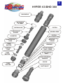
2
HYPER 63/DHD 360
BACKHEAD
BACKHEAD
‘O’ RING
CHECKVALVE
PISTON
CHECKVALVE
SPRING
WEARSLEEVE
PISTON
RETAINING RING
DIVERTER
BEARING
‘O’RING
COMPRESSION
RING
TUBE
BUFFER
BEARING
CONTROL
TUBE
BIT RETAINING
RING ‘O’RING
TUBE
BUFFER
BIT RETAINING
RING
CHUCK RELEASE
WASHER
CHUCK
TUBE
HOLDER
BUTTON BIT
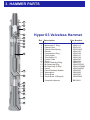
3. HAMMER PARTS
1
3
2
4
Hyper 63 Valveless Hammer
5
6
7
8
9
16
10
11
18
17
12
13
15
18
Ref Description
1
2
3
4
5
6
7
8
9
10
11
12
13
14
15
16
17
18
Part Number
Backhead
Backhead ‘O’ Ring
Check Valve
Check Valve Spring
Diverter
Compression Ring
Tube Holder
Tube Buffer (2)
Control Tube
Piston
Piston Retaining Ring
Bit Retaining Ring
Bit Retaining ‘O’Ring
Chuck
Chuck Release Washer
Wearsleeve
Guide Bush
Guide Bush ‘O’Rings(2)
HSH633803M
HSH6114
IPRCV04
IPRCVS04
HSH6120
HSH6128
HSH6131
HSH6129
HSH6330
HSH6103
HSH6132
HSH6337093
HSH6137A093
HSH6335093
HSH6326
HSH6300
HSH6386
HSH6386A
Complete Hammer
BR63H01
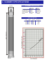
4. HAMMER SPECIFICATIONS
OUTSIDE
DIAMETER
H63 HAMMER SPECIFICATIONS
English
Metric
216 lbs
48.6”
5.62”
49.0 lbs
4.25”
98.1 kgs
1235 mm
142.8 mm
22.3 kgs
108mm
Weight (less bit)
Length (less bit)
Outside Diameter
Piston Weight
Stroke
AIR CONSUMPTION
LENGTH WITHOUT BIT
P.S.I
150
200
250
350I
BAR
10.3
13.8
17.2
20.7
C.F.M
264
522
730
958
Cu.Mtr/min
9.6
14.8
20.7
27.1
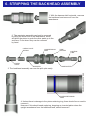
5. STRIPPING THE CHUCK ASSEMBLY
Breakout Washer
After extensive drilling, the chuck
might become to tight to loosen
on a Bulroc Bench Splitter or the
drill rig.
If this problem occurs the breakout
washer can be ground or drilled
out, which will relieve the pressure
and enable the chuck to be
removed.
(NB On no account should the wearsleeve be impacted by a hand
hammer. Splitting should not be assisted by the use of localised heat
i.e. Blow torch.)
Assuming now both the Chuck and Backhead threads have been loosened either on the drilling
rig, or a hammer splitter. The stripping procedure is as follows.
1. Remove the chuck
assembly
2. The bearing can now be
removed. Inspect both ‘O’rings
for damage.
3. Removing the ‘O’ Ring from the bit
retaining ring will allow this to be removed.
Alternatively pulling the two pieces apart
will allow the ‘O’ring to stretch enough to
fit over the end of the bit shank.
4. The bit can now be removed
quite easily.
6. STRIPPING THE BACKHEAD ASSEMBLY
1. With the hammer laid horizontal, unscrew
the backhead and remove it from the
wearsleeve.
2. The remaining assembly can best be removed
by lifting the chuck end of the wearsleeve, which
will allow the piston to push the other parts up to the
end face. From where they can be removed
by hand.
CHECK VALVE
SPRING
CHECK
VALVE
COMPRESSION
RING
DIVERTER
TUBE
HOLDER
CONTROL
TUBE
TUBE BUFFER
WEARSLEEVE CHUCK END
3. The backhead assembly can now be split quite easily.
PISTON RETAINING
RING
4. Unless there is damage to the piston retaining ring, there should be no need to
remove it.
However if this should need replacing, dropping an inverted piston down the
upright wearsleeve from the backhead end, should remove it.
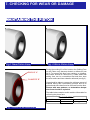
7. CHECKING FOR WEAR OR DAMAGE
Premature wear to internal parts is a result of either:1. Incorrect or insufficient lubrication.
2. The ingress of debris into the hammer.
3. Incorrect service and storage.
The maximum wear allowances shown in this section are a guide as to
when to replace parts. In certain conditions parts may need to be replaced
before they reach the sizes shown.
PISTON
STRIKING FACE
BODY DIA. ‘A’
1. There are two main areas to examine on a used Piston. Check the Body diameter 'A' for signs of
'Pick-up' and heat-caused discolouring (both are signs of poor lubrication.) Using a micrometer,
measure the diameter and refer to the table for the minimum size.
Any light 'Pick-up' marks can be removed by using emery cloth, however if there are signs
of overheating and cracking, the Piston should be replaced and the lubrication system examined.
HAMMER
HYPER63
MINIMUM DIA. (A)
4.575” (116.21mm)
2. Secondly, examine the Striking Face. Distortion is acceptable providing there are no signs of
cracking. Burrs and dents can be removed with an emery stone.
7. CHECKING FOR WEAR OR DAMAGE
MAINTAINING THE PISTON
Fig.1 New Piston Face
RADIUS “A”
CHAMFER “B”
Fig. 2 Worn Piston Face
During the working life of the hammer the Striking Face
on the Piston may become dented or deformed (see
fig.2). To prevent this face from cracking, or chipping,
the Piston should be returned to a lathe where the
strking face can be re-machined flat and then have
the outer radius and inner chamfer reformed (see fig.3)..
Care should be taken to remove the minimum amout of
material during this re-machining process and at no
point should more than 2mm be removed from the face.
Pistons with wear patterns, or indentations deeper
than 2mm should be replaced.
The table below contains useful machine information for
reforming the piston face.
MACHINE DETAIL
HAMMER
HYPER 63
Fig. 3 Area to be machined
RADIUS “A”
0.125”
CHAMFER “B”
0.060” @45
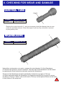
8. CHECKING FOR WEAR AND DAMAGE
CONTROL TUBE
Diameter
‘A’
HAMMER
HYPER63
MINIMUM DIA. (A)
1.875” (47.62mm)
Examine the control tube dia ‘A’, using a micrometer, check the diameter has not worn
under the specified minimum. If there are signs of ‘pick up’ they should be removed
by using emery cloth.
WEARSLEEVE
HAMMER
MINIMUM DIA. (A)
HYPER63
5.25” (133.35mm)
‘A’
‘A’
Using either a micrometer or a vernier, measure the outer diameter 'A' of the Wearsleeve.
If it is below the minimum it must be replaced. The wear rate of the Wearsleeve can be slowed
by replacing the Chuck before the wear area reaches the Wearsleeve.
The bore of the Wearsleeve should be periodically checked for any signs of 'Pick-up'.
If a Piston has broken within the Wearsleeve it is imperative that the bore is honed to remove
any Burrs or 'Pick-up'. Failure to do so will result in 'Pick-up' on the replaced Piston and will lead
to early failure of this component.
9. REBUILDING THE HAMMER
1. Ensure all maintenance work outlined in the previous
sections have been carried out.
8.Backhead
7.Checkvalve
Assembly
6.Compression
Ring
2. Stand the wearsleeve on the floor, with the chuck
end upwards.
Insert the piston retaining ring into the bore, and hammer
the ring down until it springs into the groove in the
wearsleeve.
3.Clamp the wearsleeve horizontally in a vice, taking care
not to overtighten the jaws. Assemble the chuck, chuck
release washer, and bit retainers. (ensure you fit a new
‘O’ring). Slide the bearing over the shank, ensuring the
correct orientation. (see diagram on the left), ensure you
again fit new ‘O’rings.
Cover the threads with a copper based grease.
4. Coat the piston with rock drill oil and slide it into the
backhead end of the wearsleeve. Ensure the piston
striking face enters first.
5.Control
Tube Assembly
4. Piston
5. Assemble the two control tube buffers around the control
tube and the push the assembly into the tube holder.
Coat the ouside of the assembly with rock drill oil, and insert
it into the backhead end of the wearsleeve.
6. Slide the compression ring on to the control tube assembly.
2. Piston
Retaining Ring
3.Chuck
Assembly
7. Insert the spring and the check valve into the diverter, and
push the whole assembly into the wearsleeve. Until it
reaches the compression ring.
8. Fit a new ‘O’ring to the backhead and coat the threads
in copper based thread grease. Screw the backhead into the
wearsleeve until it is fingertight. Then measure the gap
between the wearsleeve face and the lock-up face on the
backhead. This gap should be a minimum of 1mm. If the
gap is smaller, the assembly should be removed and a new
compression ring should be fitted. If the gap is greater than
1mm, the back head should be fully tightened using an
appropriate backhead spanner.
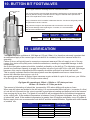
10. BUTTON BIT FOOTVALVES
Bulroc Hyper Hammers are designed to be used with footvalves.
The correct footvalve must be fitted otherwise the performance of the hammer will be
seriously affected. Using a footvalve which is larger in diameter than specified will
result in the rapid failure of the footvalve.
Using a footvalve which is smaller in diameter than the size shown will greatly reduce
the performance of the hammer.
PROTRUSION
HEIGHT ‘A’
INSERTION TOOL
FOOT VALVE
Ø’B’
The protrusion height is also important and to ensure the correct height
and prevent damage when replacing the footvalve, it is recommended
that the correct insertion tool
INSERTION PROTUSION
TOOL
HEIGHT ‘A’
HYPER63
FOOTVALVE
DIA. ‘B’
FVIT093 1.940” (49.3mm)1.500” (38.1mm)
SHANK
TYPE
DHD360
11. LUBRICATION
The Hyper 63 piston oscillates at 1000 bpm at 150 psi (10bar). It is therefore extremely important that
an adequate supply of the correct type of rock drill oil is constantly fed to the hammer whilst it is
operating.
Failure to do so will quickly lead to excessive component wear and if the oil supply is cut of for any
reason, the piston will quickly seize inside the wearsleeve, resulting in irreparable damage to both
components.
An air line lubrication system should be installed, preferably on the drill rig. The lubricator reservoir
should be of sufficient capacity to supply the required volume of rock drill oil for a full shift. With larger
hammers, this may be impractical but the capacity should be sufficient for at least half a shift.
This is equally important that the lubricator system must be adjustable and have a visual check to
ensure the lubricator does not run out of oil.
As a good general guide, all Bulroc Hyper hammers require a third of a pint of oil per hour, per 100cfm
of air through the hammer ( 0.07 litre per metre cubed)
Eg Hyper 63 operating at 150psi = 328cfm = 1.27 pints per hour
10.3bar = 9.31cmm = 0.72 litre per hour
The amount of lubricating oil should be increased by 50% when drilling with water or foam.
When new drill pipes are added to the drill string, it is recommended that a half pint ( a quarter of a litre)
of rock drill oil is poured into the pipe to provide a good internal coating and helps prevent the hammer
from running dry at any time. The grade of rock drill oil will be determined by the ambient temperature
at the drilling site. If the ambient temperature is between 0 and 25 degree centigrade, then a 30 grade
oil should be used. If the ambient temperature is greater than 25 degree centigrade, use a 50 grade oil.
Bulroc supply their own recommended rock drill oil and this is detailed below, together with other brands
of suitable oils.
MAKE
BULROC
BP
CHEVRON
SHELL
ESSO/EXXON
MEDIUM SAE 30
ISO VG 100
T220
ENGERGOL RD-E 100
ARIES 100
TORCULA 100
AROX EP100
HEAVY SAE 50
ISO VG 220
T320
ENERGOL RD-E 300
ARIES 320
TORCULA 320
AROX EP320
12. HYPER HAMMERS STORAGE
We recommend following these points listed below when removing a ‘Down the Hole Hammer from
service. This will ensure trouble-free operation once the hammer starts work again.
The hammer should be stripped and cleaned, and freed of as much water/ moisture as possible.
Bulroc T220 or similar rock drill oil should be poured into the backhead allowing all parts to be
coated throughout the hammer. Amount required for a Hyper 63 is ¾ of a pint or 0.43 litre.
Both ends of the hammer should be then covered to prevent the ingress of dirt, etc.
It should then be laid horizontally in a dry environment ready for use next time
If this procedure is followed then apart from protecting the hammer from corrosion it will protect
the parts from premature wear, and of course reduce ‘down time’ and eventual repair costs.
However we strongly recommend that the hammer, especially if stored for any long period of time
should be stripped, cleaned, inspected and re-oiled prior to use to be sure of smooth drilling..
13. TROUBLESHOOTING
PROBLEM
PROBABLE CAUSE
REMEDY
INOPERATIVE DRILL
Drill bit blowholes blocked
Dirt inside drill
Worn or damaged parts
Insufficient lubrication
Excessive lubrication
Hanging Piston
Insufficient air pressure
SLOW PENETRATION
Insufficient air pressure
Dull drill bit
Worn drill parts
Too much or too little lubrication
Unblock holes
Strip and clean drill
Replace damaged parts
Check oil level, adjust lube needle value
Adjust lube needle value
Pistion stuck. Polish out the score marks
Check compressor discharge and increase
to operational value
Increase discharge pressure
Re-grind or change bit
Replace worn parts
Check oil level and if necessary adjust lube
needle value
Strip and clean
Drill or increase hole size through the
piston
Clean out blockage
Overhaul drill
Check lubrication
Replace bit
Strip and clean
LOW RETURN AIR VELOCITY
SPASMODIC OPERATION
Dirt in drill
Insufficient hole flushing air passing
through hammer
Drill bit exhaust holes blocked
Failed or damaged parts
Lack of oil
Drill bit broken
Dirt in drill
A. CHUCK RELEASE WASHERS
CHUCK RELEASE WASHERS
HAMMER
“W”
“D”
MODEL
HYPER 63
0.310” - 7.87mm 0.295” - 7.49mm
Chuck Release Washers are fitted to the Bulroc Range of Hyper Hammers to assist the removal of the
Chuck from the Wearsleeve after drilling.
The Chuck Release Washer is manufactured from a composite material that reduces the friction between the
lock up faces on the Chuck and Wearsleeve making it easier to overcome the tensional loading applied
to these parts during the drilling process.
Due to the forces applied to the Chuck Release Washer you may find that its thickness ("W") is reduced
during the drilling cycle and it is therefore recommended that a new Washer be fitted each time the
Chuck is removed.
It is possible that on some of the larger Hammers in the Bulroc range, when drilling with large diameter
Button Bits or Overburden Systems, certain conditions can generate higher torques than normally
expected, resulting in difficulties when trying to remove the Chuck from the Wearsleeve. Should this occur
then the removal of the Chuck can be achieved by cutting away the Chuck Release Washer. We do
however stress at this point that cutting away the Chuck Release Washer is a final option and should
not be done until all other options have proved unsuccessful.
If the cutting away of the Chuck Release Washer is necessary for the removal of the Chuck then it must
be done with extreme care to avoid damage to either the Chuck or the Wearsleeve. The composition
of the Chuck Release Washer allows for it to be cut with either a hacksaw or a small hand grinder equipped
with a slitting wheel. The hacksaw method is much safer and less likely to damage the Chuck or Wearsleeve,
but obviously much slower than the hand grinder with a slitting wheel. To remove the Chuck Release Washer
a cut must be made in the centre of the washer all the way around it's circumference, and
completely through the Washer, thus transforming the single washer into two thinner washers that will
then spin freely. Great care must be taken, especially if the Washer is cut with a slitting wheel, to ensure
that the cut only penetrates the Washer and does not pass through into the body of the Chuck.
The size shown as 'D" in the above table should be your MAXIMUM depth of cut, and it is recommended
that either the saw blade or the slitting wheel are marked in some way so as to indicate when they have
achieved this depth.
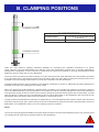
B. CLAMPING POSITIONS
x
CLAMPING POSITION
CLAMP POSITIONS
HAMMER MODEL
Hyper 63
“X” DISTANCE FROM WEARSLEEVE
END FACE
7.750” / 197mm
CLAMPING POSITION
x
There are many different “Splitting” Machines available for unscrewing the threaded connections on a Bulroc
Hyper Hammer, some are attachments to the Drill Rig, others are independent hydraulic units, or purpose made Bench
arrangements. Regardless of which machine is chosen they all require some method of securing the Wearsleeve whilst
applying a torque to either the Chuck or Backhead.
The most common machines use either Clamps or Chains around the O/D of the Wearsleeve and the positioning of these
is very important, if they are placed too close to the joint being “Split” they will in effect increase the frictional forces on the
threaded connection making it impossible to unscrew the component from the Wearsleeve.
The above table shows the correct position for the clamping mechanism to ensure no additional load will be applied to the
threaded connection, thus making the joint easier to split.
Due to the high torque loads applied to a Hammer during its drilling cycle, equally high loads are required to “Split” the
Chuck and Backhead away from the Wearsleeve and because of this the clamping arrangement around the Wearsleeve
must generate enough friction to prevent it from spinning during the process.However great care must be taken to make
sure the clamps or chains are not over-tightened as this can cause deformation to the Wearsleeve that can result in both
Wearsleeve failure and Piston seizure once the Hammer is returned to service.
To help increase the Wearsleeve’s resistance to deformation it is recommended that the Hammer Piston is first slid to the
end of the Hammer being “split”, before clamps of chains are attached. By doing this the Piston O/D will limit the amount of
deformation in the Wearsleeve bore if too much clamping pressure is applied.
NOTE:
The use of Chain type Hydraulic Breakers can leave deep intrusions in the O/D of the Wearsleeve which may result in stress
concentrations that could lead to premature failure of the Wearsleeve.
Manufacturers of Rock Drilling Equipment
Turnoaks Business Park, Burley Close, Chesterfield ,Derbyshire S40 2UB
Tel: +44(0) 1246 544700 Fax: +44(0) 1246 544701
E-mail: [email protected] website bulroc.com
HYPER 63DHD360 16/01/15