1
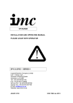
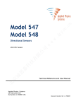
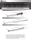
CDS-RS
CDS-240RS /
DHD380/SD8/QL80
MAINTENANCE, OPERATING
AND SERVICE MANUAL
PATENTED AIRFLOW SYSTEM
1. INTRODUCTION
The Bulroc CDS-240RS Overburden System is a concentric drilling system designed to
simultaneously case a hole through loose overburden conditions down into the solid bedrock with minimal
disturbance to surrounding sub-structures.
This system has a multi-stage-cutting head to guarantee the drilled hole is straight with minimum
deviation. The independent segments around the periphery of the head give equal concentric cutting
forces resulting in fast, low torque drilling.
Since “down time” is very costly, this system is designed to require the minimum amount of maintenance.
However when parts do eventually wear, the construction of the system is such that the areas of the
cutting head which experience most wear, can be replaced independent of the slower wearing areas
and so minimise operating costs.
LIST OF CONTENTS
GENERAL
INTRODUCTION
INDEX
USING THE CDS-2400RS
1
1
2
USING THE CDS-240RS SYSTEM
CALCULATING THE LENGTHS FOR STARTER CASINGS
CASING SHOE SIZES
SYSTEM PARAMETERS
PARTS LIST CDS-240RS
SERVICING
HOW THE SYSTEM WORKS
3
3
3
4
5-6
7
REFURBISHING WORN EQUIPMENT
RING BIT & THE SEGMENTS
THE DRIVER
WELDING THE DRIVER
8
8
9
TROUBLE SHOOTING
HINTS AND TIPS
NOTES
10-12
13
2. USING THE CDS-240RS
Drill Rigs :Drill rigs on which the CDS-240RS is to be used should have a feed length at
least one metre more than the longest casing. This will allow sufficient clearance for
any adapters or drive subs required by the system.
Drill Tubes :We recommend standard 4 ½” api reg x 5 ½” OD (140mm OD) drill tubes should be
used with this size system.
However, it will be necessary to effectively reduce the annulus area between the drill
tube and the ID (Inner Diameter) of the casing which in turn will increase the ‘up hole
velocity’ of the exhaust air for efficient removal of the drill cuttings and also prevent
blockages occurring inside the casing
The drill tubes should therefore be sleeved using standard 8 casing (8.625” / 219mm).
The hammer must also be cased over the full length down to the chuck.
The length of the sleeved drill tubes should be identical to the length of the casings to
maintain the initial protrusion length from the starter casing so as to ensure access to
the spanner flats on the drill pipes.
UP HOLE VELOCITY FORMULA (METRIC)
VM = Y(CFM) x 1305096
DM²- dm²
VM = Velocity in m / min
Y = Volume of air passed by Hammer at the selected pressure.
m3/min
DM² = Diameter of casing bore squared (in mm)
Dm² = Diameter of tube sleeve squared (in mm)
UP HOLE VELOCITY FORMULA (IMPERIAL)
VF = Y(CFM) x 183.4
Dl²- di²
VF = Velocity in feet / min
Y = Volume of air passed by Hammer at the selected pressure.
Ft3/min
Dl² = Diameter of casing bore- squared (in inches)
Di² = Diameter of tube sleeve squared (in inches)
3. CALCULATING LENGTHS FOR STARTER CASINGS
1508mm Starter Casing including shoe
3m Casing
38mm Shoe length
397mm
1409mm hammer length
3m Rod
The above diagram shows the length of starter casing required when using standard CDS-RS
equipment with the Bulroc HYPER 81 hammer. If an alternative hammer is to be used, the starter
casing length can be calculated by either adding or subtracting the difference in effective length of
the alternative hammer from that of the HYPER 81 hammer.
273mm
256mm
System parameters
76mm
Reamed Dia
296mm
114mm
Body Dia
240mm
260mm
259mm
243mm
Casing Shoe Size
5..CDS560R
4
CDS-240RS
Parts
PARTS
List LIST
5
3
1/1a/1b
6/6a/6b
4
2
SPEC IFIC ATIO N S
Description
C O MPO N EN T PA R TS
Ref
Metric
Major Body Diameter
256 mm
Length (less Foot Valve DHD380)
Length (less Foot Valve SD8)
Length (less Foot Valve QL80)
745 mm
740 mm
720 mm
System Open
296 mm
Casing Size
Total Weight DHD380 Shank
Total Weight SD8 Shank Total
Weight QL80 Shank
273mm OD x 260mm ID
136 Kg
135 Kg
136 Kg
Description
Part No.
1
1a
1b
Driver (DHD380)
Driver (SD8)
Driver (QL80)
CDS240DH094RS
CDS240DH045RS
CDS240DH108RS
2
Ring Bit
CDS240RRING
3
Seloc Pin Set
CDS240RSP
4
Solid Retaining Pin
CDS240RRP
5
Segments (3)
CDS240RSEG
6
Foot Valve (DHD380)
Foot Valve (SD8)
Foot Valve (QL80)
BBF094
BBF045
BBF108
Complete System
CDS240094RS
CDS240045RS
CDS240108RS
5. CDS-240RS SERVICING
The CDS-240RS system is designed to require the minimum amount of service and
maintenance. However, it is recommended that the system be stripped down every 250 metres
and all the component parts checked for wear or damage.
Eventually the segments will need to be replaced and most likely, the buttons on the ring bit will
require re-grinding. At this time, the following procedures must be followed:-
1. First remove both the Retaining Pin (4) and Seloc Pins (3)
holding the Ring Bit by grinding out the tack weld (push out as
shown). Hammering gently will force the Pins out of their housing
but should this prove difficult, applying liberal amount of penetrating
oil should ease the process.
2. Once the Pins are removed rotate the Ring anticlockwise until it stops, then pull forward to remove.
3. The segments are now free to
be withdrawn from their sockets.
6. CDS-240RS SERVICING (CONTINUED)
At this point, the segment bushes or sleeves can be examined.
These bushes are pressed into the driver to prevent wear whilst the segments are cutting and they are
manufactured from hard, wear resistant steel that should outlast many segment changes before they will
require replacing.
Before re-assembling the system, it is important to check the condition of the slots in the driver where
the ring bit lugs locate. These slots may show some degree of wear and deformation and any signs of
deformation must be removed using a small pencil grinder or similar to ensure correct location and drive
of the ring bit. This is particularly important if a NEW ring bit is being fitted to a WORN driver.
Re-assembly Instructions
To re-assemble the system insert the new or
re-sharpened segments into their sockets and
slide the new or refurbished drive ring onto the
driver and rotate clockwise until it stops.
SELOC PIN SET
RETAINING PIN
Now insert a NEW retaining
pin and gently drive home with
the punch before finally
inserting a new Seloc Pins.
Finally ensure a spot of tack
weld is applied to secure the
Pins in position so they cannot
come out.
Recommendations for refurbishing
worn components are given in page 8
7. HOW THE SYSTEM WORKS
2
1
3
The Bulroc CDS-240RS overburden system is designed to enable the
operator to drill and simultaneously case a hole through loose overburden
ground conditions down into solid rock.
(See diagram 1)
After reaching the required depth, the segments can be moved into the closed
position by pulling the system up against the casing shoe and counter
rotating. If the hole has reached solid rock at its required depth, then the
system can be closed by resting the system on the bottom of the hole and
again, counter rotating. With the segments fully closed, the system can now
be retracted through the casing leaving a clean, cased hole. (See diagram 2)
Should it be necessary to drill on further into the solid rock, the CDS-RS
system can be detached from the Hammer and replaced with a conventional
drill bit that can pass through the casing shoe. (See diagram 3)
The Bulroc CDS-RS overburden system simultaneously cases the hole
by means of a shoulder on the driver. This shoulder locates against the top
face of the casing shoe, which is welded into the starter casing. Since the
casing does not rotate with the drill tubes, the torsional loads are relatively low
and so either left hand threaded or welded casing can be used.
8. REFURBISHING WORN EQUIPMENT
The Ring bit and Segments
The most frequent cause of button failure can be attributed to over drilling and incorrect button regrinding.
Regrinding at regular intervals, with the correct equipment, not only improves component life but also
improves production and reduced overall drilling costs.
1) Buttons should be reground to their original shape when the wear flat is 1/3rd the diameter of the
button.
2) If the button is cracked or chipped, it should be ground back flush to the steel matrix. It is possible to
carry on drilling with a number of broken buttons if they are ground back in this way, providing they are
not affecting the gauge diameter, or are not adjacent to each other since this would affect the smooth
rotation of the bit.
3) After regrinding check the protrusion heights of the buttons. If a button protrudes too far from the
steel body it will cause premature failure of the button. The side protection buttons should be ground
back flush with the body. The gauge buttons should be ground back until their protrusion height is 1/2
their diameter.
To perform the task of regrinding correctly, we recommend the use of a hand held grinder with gravity
fed water supply necessary to cool the impregnated diamond grinding cups.
A combo type grinding cup of the approximate diameter will remove the surrounding steel matrix and
reform the carbide button at the same time.
The Driver
The shoulder on the driver where it contacts against the casing shoe will eventually wear. This is quite
normal and to be expected. However, when the drive shoulder does become worn to a taper shape, it
will begin to jam in the casing shoe.
At this point, it will be necessary to re-form the drive shoulder back to its original 30 degree angle by
welding up this area of the original shoulder. It is important that the following procedures are strictly
followed to avoid damage and cracking of the driver.
The same type of wear will also occur on the replaceable drive ring if you are using this design of driver.
However, in this case, all that is necessary is to burn off the old worn ring and replace it with a new drive
ring. This comes in two halves that require welding around the driver recess. It is important that the
system is used with a well fitting casing shoe, which has the same 30 degree angle. A badly worn
casing shoe will cause rapid wear and unnecessary wear to a new or re-formed drive shoulder on the
driver.
9. WELDING THE DRIVER
WELDING PROCEDURES
1 - The bit holder must be preheated to between 200oC and 250oC before any welding takes
place.
2 - This temperature must be maintained throughout the welding process - check temperature
frequently using temp sticks.
3 - The weld must be applied in single runs around the shoulder area building it up to as near
the original shape as possible.
Use 1mm CARBOFIL CRM01. AWSAS.28ER 80S/g or equivalent.
Weld
Bit Holder
Bit Holder (After Re-machining)
4 - After welding the holder must be slow cooled. This can be achieved by either burying the
holder in a tank of vermiculite or similar, or by wrapping it in an asbestos blanket. This slow
cooling is a very important part of the process. Rapid cooling can cause cracking.
5 - Once the holder has returned to room temperature it should be turned on a lathe back to
its original shape.
Dimensions for turning are given in the table on page 3. The correct shape is important to avoid
rapid wear of the casing shoes and subsequent wear of the bit holder.
If a lathe is not available then a small hand grinder can be used to reform the drive shoulder.
Great care must be taken to get the surface even, and correctly form the 30 degree shoulder,
if the surface is uneven and the angle incorrect it will lead to premature wear and jamming.
10. HINTS AND TIPS
Always Do the Following
1. Make sure the Driver will pass through all the lengths of casing intended for the job. If
the casing is to be welded, extra clearance should be allowed for weld spots, which may
break through into the inside of the casing.
2. If the casing is to be welded then the ends should be bevelled at an angle between
45 and 60 degrees. To prevent weld breaking through, and to help alignment, a 3mm
wide land should be left on each end face.
If the casing is the threaded type, then it must be left hand. Because of the cost of the
thicker walled casing required to produce a thread, it is normal practice to have
threaded joints welded on to the end of thinner casing, thus keeping the cost to a
minimum. If this is the case then great care must be taken to ensure the joints are true
and concentric to the casing. An out of line joint can result in either the system jamming
inside the casing, or the casing jamming in the hole. As with welded casing, the joints
should have bevelled end faces to prevent weld breaking through into the inside of the
casing.
3. Check the casing shoes before the job starts. The inside diameter of the shoe should
be within the following tolerances.
CDS-240RS
Minimum mm
Maximum mm
241.5
243
4. Check the length of the casing shoes. When in position against the drive shoulder on
the driver there should be between 12mm and 25mm clearance between the back face of
the segments and the front face of the casing shoe - depending on the size of the
system. This distance will increase as the drive shoulder and/or the casing shoe wears.
5. Make sure the segments swing from open, to closed position freely by hand.
6. Use the diagram on page 3 to make sure the correct length of starter casing has been
calculated.
7. When drilling commences, use slow forward rotation. If jamming occurs, ease back on
the feed force or lift the CDS-RS and the casing until rotation starts again. Initially, the
casing may rotate but after drilling down the casing 1-2 meters, it will stop rotating.
8. Apply only light feed and reduced air pressure when setting the first casing and make
sure the casing stays in line with the drill mast.
9. When drilling through soft materials (sand, clays etc.) frequently lift the CDS-RS and
the casing a little to ensure that it is loose and to flush out any debris from the casing.
When the CDS-RS is in the "hang position", all available air will go to directly flushing
the casing. In sand and gravels, it is often preferable to reduce air and feed pressure to a
minimum. In all ground conditions, it is good practice to lift the casing frequently to make
sure it is loose and to clear all debris from the casing.
11. HINTS AND TIPS (CONTINUED)
10. When drilling in sticky, plastic clay, the addition of water or even foaming agents in the
hammer air may be necessary to maintain good flushing.
11. When drilling through boulders or inclined rock faces the fact that this concentric
system has a number of independently operating segments. With a concentric system the
independent segments only require a very small amount of movement to travel from the
open to closed position, this is somewhere in the region of 20 to 30 degrees rotation of the
system. Consequently if you attempt to hammer without rotation then the segments will
swing back into the closed position causing the system to produce a socket in the rock that
is only the diameter of the pilot bit. So once rotation is resumed the segments cannot open
back out as they are retained by the sides of the rock socket.
To prevent this occurring a concentric system should have its RPM increased and feed rate
reduced, once it starts to encounter boulders or inclined rock. By doing this you guarantee
that the segments remain in the open position even if their contact with the rock is
intermittent. The system should then be fed slowly into the boulder, or rock face, until
continuous cutting can be heard. At no time must the rotation be stopped whilst hammering
is taking place. If at any point the system starts to jam against the inclined face it must be
immediately pulled back and then slowly fed forward back into the rock.
Once the system has formed a complete socket in the rock the speed and feed can be
reduced back to the correct rates suitable to the type of rock being drilled. The segments on
this concentric system should be much easier to move from open to closed position and
consequently the most important consideration when using a concentric system is to
maintain clockwise rotation throughout the entire drilling cycle. The only time reverse
rotation should be applied is when you wish to close the segments, and at no time should
the system be hammered without rotation as this will either allow the segments to vibrate
back into a closed position, or if this doesn't happen then the segments will form three
sockets in the rock that could generate extremely high torque loads once rotation was
re-applied.
12. When the casing has been set to the required depth, and when drilling in sticky
ground, care must be taken to clean out the inside of the casing before extracting the
drillstring. Water poured inside the casing repeatedly and flushed out will help the process.
On occasions it may be necessary to pull the CDS-RS system back into the casing to
flush out blockages. To perform this task the system should be lifted into the "hang"
position and rotated clockwise for 2 or 3 revolutions to ensure the bit face is clean. The
system should then be pulled back against the casing shoe and the air turned off. At this
point the rod should be marked to give a reference point for when the system is fed back
through the shoe. Reverse rotation for 1 revolution will then close the segments and allow
the system to be pulled back into the casing. Once inside, the air can be turned back on
and the system should then be moved up and down inside the casing until the blockage is
cleared. At no time must the system be rotated whilst it is inside the casing as this will
cause the segments to jam against the casing wall.
12. HINTS AND TIPS (CONTINUED)
When the casing is clean the system should be fed back through the shoe using the
reference point on the rod to indicate when it is through the shoe. Once through the shoe
the system can be rotated clockwise to open out the segments.
13. Always re-grind worn buttons.
Never do the Following
1. Penetrate too fast in loose ground. Overfeeding will "bury" the CDS-RS and block the
casing with nowhere for the hammer air to exhaust, hence stopping the hammer. Always
give the flushing air a chance to bail out the debris and keep the casing clear.
2. Over rotate. This will lead to premature button wear. In rock or boulders, rotation of the
CDS-240RS should be between 14 to 16 rpm. In loose ground conditions this can be
increased by 50%.
3. Apply weld to either the ring bit or the segments. This can lead to cracking and button
failure. No warranty can be considered on these parts if there is any evidence of welding.
Bulroc’s CDS-RS range of overburden drilling systems feature patented Bulroc
Airflow technology. This document is © 2013 Bulroc UK Limited. All rights reserved.
Unauthorised duplication or distribution prohibited by law.
PATENTED AIRFLOW SYSTEM
WARNING
ALWAYS THINK
SAFETY FIRST!
This manual is published by and copyright © of Bulroc (UK) Ltd. All Rights Reserved. Always operate your Bulroc
drilling equipment according to the instructions contained within this operating manual. Further copies of this manual
can be downloaded from the Bulroc website; www.bulroc.com. For urgent support or sales enquiries, call Bulroc
on +44 (0)1246 544700 or Skype BULROCUKSALES . E & O.E.
13. NOTES
This page left intentionally blank
Bulroc (UK) Limited
Turnoaks Business Park
Burley Close
Chesterfield
Derbyshire
United Kingdom
S40 2UB
Tel: +44 (0)1246 544700
Fax: +44 (0)1246 544701
E-mail: [email protected]
Web: www.bulroc.com
© 2012 Bulroc (UK) Limited. All Rights Reserved