1
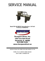
SERVICE MANUAL Model TDI-1519ECMC Series Machine– 110 Volt Economy Combination Thompson Direct, Inc. 2397 Von Esch Road Plainfield, IL. 60586 815-609-5164 www.thompsondirect.us _____________________________________________________________ INSTRUCTIONS FOR OPERATION AND REPAIR OF THE MODEL TDI-1519ECMC SERIES SEALER AND TUNNEL COMBINATION Thompson Direct, Inc.Type text] IMPORTANT - PLEASE READ THIS CAREFULLY The development of a good safety program, that is rigidly enforced, is absolutely imperative when involved in the operation of industrial equipment. Our machinery is well designed and includes extremely important safety features. The part you the user play through proper installation and maintenance procedures is of far greater significance than our designs. Only properly trained individuals following rigidly enforced safety rules, as recommended by A.N.S.I. and O.S.H.A., should be allowed to operate these machines. Thompson Direct, Inc.Type text] TABLE OF CONTENTS ___________________________________________________________ Preface Unpacking Warranty Notice Warranty Warranty Exceptions Warnings 4-8 9 10-11 12 13-15 Tunnel Section Description and Specifications Installation and Basic Set-Up Film Threading Diagram Front Panel Diagram Temperature Control Adjustment Sequence of Operation Troubleshooting -- L’Sealer Troubleshooting – Tunnel Maintenance Tunnel Maintenance – L’Sealer 16 17-23 24 25 26 27-31 32-46 47-55 56-70 71-79 Electrical Schematic – NOTICE! Electrical Schematic Model TDI-1519ECMC Electrical Panel Diagram Model TDI-1519ECMC 80 81 82 Electrical Schematic Model TDI-1519ECMC Electrical Panel Diagram Model TDI-1519ECMC 83 84 Electrical Schematic Model TDI-1519ECMC Electrical Panel Diagram Model TDI-1519ECMC 85-86 87 Parts Nomenclature Replacement Parts List -- Sealer Replacement Parts List – Tunnel Spare Parts List 88-89 90-91 92-93 94 Thompson Direct, Inc.Type text] UNPACKING THOROUGHLY INSPECT EQUIPMENT UPON ARRIVAL. If goods are received short or in a damaged condition, it is important that you notify the carrier’s driver before he leaves your company and insist on a notation of the loss or damage across the face of the freight bill. Unless this is done, no claim can be enforced against the transportation company. If concealed loss or damage is discovered, notify the carrier at once and insist on an inspection. This is absolutely necessary! A concealed damage report must be made no later than ten (10) days from the date the shipment was delivered. Unless you do this, the carrier will not consider any claim for loss or damage. The carrier’s agent will then make an inspection and grant a concealed damage notation. If you give the transportation company a clear receipt for the goods that have been damaged or lost in transit, you do so at your own risk and expense. All claims must be filed within 10 days of delivery date or carrier will not accept them. Thompson Direct, Inc. is willing to assist in every possible manner to collect claims for loss or damage; however, this does not hold Thompson Direct, Inc. responsible for collection on claims or replacement of material. Do not throw away damaged pallets or box until freight inspection has occurred. UNPACKING Thompson Direct, Inc.Type text] Your new Model TDI-1519ECMC comes bolted to a pallet and has a tri-walled corrugated box strapped to the pallet to protect it. 1. If your machine does not arrive in this condition, write on shipping paperwork that outside of box is damaged. Concealed damage may have occurred. 2. Remove stretch film and Poly Bag covering machine. UNPACKING Thompson Direct, Inc.Type text] Film Rack 3. Remove film rack from under L’Sealer. 4. Check film rack. You should have (a) (1) Film Rack (b) (1) adjustable center knob (c) (2) film roll guides 5. Cut plastic strap from top and bottom of conveyor rollers before attempting to operate conveyor. UNPACKING Thompson Direct, Inc.Type text] 6. Mount film rack on right side at end of machine (see page 18 for instructions). 7. Remove bolts holding L’ Sealer to pallet using 13-mm wrench. 8. Place forks of forklift under center of frame of machine and lift off pallet. 9. Place in desired location and use locking casters to set in place. UNPACKING Thompson Direct, Inc.Type text] IMPORTANT WARRANTY NOTICES OPERATING AND MAINTENANCE MANUAL The operating and maintenance manual has been carefully prepared to provide the user with all the information needed to properly install, operate, and maintain your Thompson Direct, Inc. equipment. Please read this manual carefully and refer to it for information on the care and use of your Thompson Direct, Inc. equipment. It is recommended that additional copies be ordered for use by production, maintenance, and supervisory personnel. Although the design of this equipment incorporates safeguards to protect personnel, care should be used in operating, adjusting, and servicing. Attention is directed to the warranty that accompanies all your Thompson Direct, Inc. equipment. The terms and conditions of this warranty apply only to unmodified units. Any unauthorized modifications to the equipment automatically voids this warranty. Thompson Direct, Inc. provides a one-year warranty on parts, excluding shipping or freight costs for replacement parts. All warranty parts are shipped F.O.B. Plainfield, Illinois. WARRANTY NOTICE Thompson Direct, Inc.Type text] THOMPSON DIRECT, INC. WARRANTY Thompson Direct, Inc. warrants each new product manufactured to be free from defects in material and workmanship for a period of (1) year from date of shipment by Thompson Direct, Inc. This warranty is not transferable with any subsequent resale. Defective parts under warranty must be returned to Thompson Direct, Inc. freight prepaid. Thompson Direct, Inc. sole obligation and purchaser’s sole remedy in the event of a warranty dispute shall be, at Thompson Direct, Inc. option, to repair or replace the part in question. Labor incurred in removing or installing the defective part is not covered by this warranty. Prior to returning any parts for any reason, contact Thompson Direct, Inc. for a Return Authorization Number. This number must accompany all returns. This warranty shall not apply if equipment has been tampered with, misused, improperly installed, altered, or has received damage due to abuse, carelessness, accident or failure to follow recommended regular maintenance procedures or has been serviced by someone other than a duly authorized factory representative without the express written consent of Thompson Direct, Inc. This warranty is in lieu of all other warranties, expressed or implied, including but not limited to warranties of merchantability and fitness for a particular purpose, non-infringement or any other matter. Thompson Direct, Inc. shall have no liability to any person for direct, indirect, incidental or consequential damages or delay WARRANTY Thompson Direct, Inc.Type text] resulting from any defect negligence, or tort and customer hereby waives for itself any and all claims for punitive damages and all claims of negligence of strict liability or both. In no event shall our liability exceed the purchase price of the product that was actually paid. Thompson Direct, Inc. reserves the right to make changes, additions, or improvements to our products with no obligation to make such changes in any previously shipped product covered by this warranty. Thompson Direct, Inc. shall not be held liable for any damages arising out of nor in connection with the operation of the equipment should customer or its agent fail to maintain equipment in safe operating condition. This warranty shall become unenforceable if and to the extent the customer or its agents remove, disconnect, or otherwise render useless any safety device and or parts designed or affixed by us or fails to maintain and service equipment in a manner as advised. Thompson Direct, Inc. provides a one-year warranty on parts, excluding shipping or freight costs for replacement parts. All warranty parts are shipped F.O.B. Plainfield, Illinois. Service Labor to install part is not covered under warranty! WARRANTY Thompson Direct, Inc.Type text] WARRANTY EXCEPTIONS The following parts are an exception to the general warranty list on page 10. Each part listed below shall carry a 30-day warranty unless designated otherwise. TDI-1519ECMC Series Sealer Parts 1. 2. Fuses Conveyor Belt (Optional) Tunnel Parts 1. 2. Silicone Tubing (Roller Covers) Tunnel Curtains The following sealer parts are considered to be consumable and not under warranty: 1. 2. 3. Silicone Sponge Band Ribbon Teflon Tapes WARRANTY EXCEPTIONS Thompson Direct, Inc.Type text] WARNINGS Every effort has been taken to ensure your safety while operating this machine; however, there still remain certain risks. Do not allow this machine to be operated before informing all personnel of the following warnings. WARNING........ Do not tamper with the electrical wiring. Only use a licensed electrician for maintenance. Always disconnect the electrical power before attempting any maintenance to all electrical and/or moving parts. WARNING........ In order to prevent injury to personnel and/or machinery DO NOT INCREASE SETTINGS OR RATINGS ON EITHER ELECTRICAL OR MECHANICAL OVERLOAD SAFETY DEVICES. WARNING........ KEEP HANDS AWAY FROM MOVING CONVEYORS AND ASSEMBLIES. Conveyor belts that have become worn or frayed are capable of being hazardous. They should be replaced promptly. WARNING........ NEVER OPERATE THIS OR ANY MOVING EQUIPMENT WITHOUT ALL COVERS AND GUARDS IN PLACE. The internal mechanism of most packaging machinery contains numerous shear, pinch, and inrunning nip points, many of which are capable of causing severe injury and/or permanent disfigurement. WARNINGS Thompson Direct, Inc.Type text] WARNING........ To minimize the potential for personnel injury, always be sure that machine operators and others working on the machinery are properly trained in the correct usage of the equipment and properly instructed regarding the safety procedures for operation. WARNING........ Heat sealing arms and jaws on packaging machinery can become very warm after a period of use. KEEP HANDS AWAY WHILE IN OPERATION AND USE CAUTION IF THE MACHINE HAS BEEN RUNNING RECENPPY. WARNING........ ANY MODIFICATIONS TO EITHER THE ELECTRICAL CIRCUITRY OR THE MECHANICAL ASSEMBLIES OF THE MACHINERY WILL VOID ANY WARRANTIES ASSOCIATED WITH THIS EQUIPMENT. Such modifications may introduce hazards that would not otherwise be associated with this machinery. Thompson Direct, Inc. will not be responsible for any consequences resulting from such unauthorized modifications. WARNING........ The use of certain types of plastic films in sealing and/or shrinking equipment may result in the release of HAZARDOUS FUMES due to the degradation of the film at high temperatures. Before using any plastic film in this equipment, the manufacturer or supplier of the film should be contacted for specific information concerning the potential release of hazardous fumes. ADEQUATE VENTILATION MUST BE PROVIDED AT ALL TIMES. WARNING........ It is important that the machine operator unplug the machine when he/she has finished operating the unit. WARNINGS Thompson Direct, Inc.Type text] WARNING........ Turn off machine and disconnect power cord from power source before attempting to work on machine. WARNINGS Thompson Direct, Inc.Type text] DESCRIPTION AND SPECIFICATIONS OF MODEL TDI-1519ECMC SERIES COMBINATION SEALER TUNNEL DESCRIPTION The purpose of a TDI-1519ECMC Series is for low to medium volume packaging requiring excellent seals and minimal maintenance. It features an impulse mode for sealing of films. This model incorporates an optional electromagnetic hold-down system, allowing the operator to load another package while the preceding package is being sealed. This system provides consistent seals. In addition, an optional package take-away conveyor increases production speed by automatically discharging product into the tunnel. SPECIFICATIONS Model: Seal Area: TDI-1519ECMC Series Length: 19” Width: 15” Machine Size: Length: 74” Width: 24” Height: 53” Volts: 110 Amperage: 20 Weight: 400 lbs. Tunnel Chamber Size: Length: 20” Width: 16” Height: 6” SPECIFICATIONS Thompson Direct, Inc.Type text] INSTALLATION AND BASIC SET-UP OF L’SEALER PORTION OF MACHINE IMPORTANT Read this manual carefully, and make it available to everyone connected with the supervision, maintenance, or production of this machine. Additional copies are available at your request. (Contact your distributor for this information.) Be very careful when operating, adjusting, or servicing this equipment. If in doubt, stop and obtain qualified help before proceeding. INSTALLATION OF PP-1519EC SERIES Place the TDI-1519ECMC in the desired location with the required electrical power source available. (See power requirements.) Make certain that proper electrical wiring is provided to guard against low voltage. If the voltage is too low, the equipment will not function properly. Machine comes complete with power cord and 110 volt plug. Finding the proper location is a most important function of the initial set-up. One must take several factors into consideration: 1. 2. 3. Adequate power source. Relationship to source of product. Relationship to L’Sealer. INSTALLATION Thompson Direct, Inc.Type text] 4. 5. Relationship to any conveyors necessary to remove finished product. Convenience of operator. Make sure to connect machine to an Independent Power Source. DO NOT run any other equipment on the same power line as your machine. Do not attempt to install, adjust, or operate this machine without first reading the contents of this manual. Although the design of the equipment incorporates safeguards to protect operating and maintenance personnel, care should be used in operating, adjusting, and servicing. INSTALLING FILM RACK IMPORTANT: Remove film rack from under sealer and install at the end of the sealer on the right hand side with the four bolts and center knob provided. Mounting holes are slotted for adjustment, set film rack flush with backside of the machine frame. INSTALLATION Thompson Direct, Inc.Type text] MOUNTING FILM Select the proper width of centerfold film for the item being packaged, allowing for width and height of package. With the package properly positioned within the film in the sealing area, allow sufficient film to overlap the sealing bars so that a seal may readily be made without any possibility of open areas due to insufficient film. Place film roll on cradle mount film rack. The centerfold is to be placed away from the operator, toward the rear of the machine. Use core chucks to position film roll on rack and tighten film guide nuts to hold film roll in position. PIN PERFORATOR Located between the lower idler rollers, the pin perforator creates holes for air escape as the operator pulls on the film. This allows the air to escape as the package travels through the tunnel. INSTALLATION Thompson Direct, Inc.Type text] The pin perforator is adjustable and must be properly placed in conjunction with the width of the desired package. The positioning should always be re-evaluated when setting the machine for different size product or different size film. CAM Design to Adjust Depth Thread film through the Pin Perforator. Note that the perforator wheel turns freely and is not binding. You can adjust the depth of pin holes by Loosening the Allen screw on the sponge wheel and rotate the cam to allow the pin to push deeper or shallower into the film. INSTALLATION Thompson Direct, Inc.Type text] PRODUCT TRAY The product tray is an adjustable metal platform used to separate film and to insert product between top and bottom layers of film. Once threaded, separate film top from bottom and insert product tray between. Make sure that the centerfold of film is placed at the rear of the product tray. This allows the operator to insert product between the layers of film on the product tray and to prepare to move product and film into the sealing area. When threading film, make sure to pull more than sufficient film through the rollers, across the product tray, and into the sealing area to ensure sufficient film to begin operation. The tray is adjustable to achieve proper depth, equal to the depth of the package, allowing product to be placed exactly in the centerfold of the film each time. A locking wing screw allows you to set tray position. Place product against rear of film separator tray. Then move product into seal area. Be sure to leave the bag loose around the product when making the seal. This helps eliminate the seals from blowing out in the shrink tunnel. INSTALLATION Thompson Direct, Inc.Type text] LOCKING WING SCREW Once the product is placed in the desired location, tighten the wing screw under the loading tray to lock tray in position. Optional Power Discharge Conveyor Lower Power Discharge Conveyor using the crank wheel located underneath the Power Discharge Conveyor. The Conveyor should be set so the package height is centered to the seal pad. In essence, ½ of the package is above the seal pad and the other ½ of the package is below the seal pad. This will place the seal in the center of your package and help release any film tension that may occur. INSTALLATION Thompson Direct, Inc.Type text] FILM THREADING DIAGRAM Product Pin Perf. = Film Film Roll FILM THREADING Thompson Direct, Inc.Type text] Front Panel Diagram TDI-1519ECMC 1. 2. 3. 4. Start Switch -- Green Heater Switch -- White Temperature Control Tunnel Conveyor Speed Control – Small Black Knob FRONT PANEL DIAGRAM Thompson Direct, Inc.Type text] Temperature Control Adjustment PV = Present Value SV = Set Value On the above temperature controller the set value is 300 degrees and its present temperature is at 298 degrees. To Adjust Temperature Up or Down: First you must press the arrow key that points left (). When pressing this key the set value temperature will flash first in the ones column. While flashing, you may adjust temperature by now pressing the arrow keys either up or down () to the desired temperature in the ones column. Repeat this procedure by pressing the left arrow () to move flashing light to the tens column or the hundreds column and adjust up or down to desired temperature. Once you have adjusted to desired temperature press the set key and the temperature will now become your new set value (SV). FRONT PANEL DIAGRAM Thompson Direct, Inc. Page 25 TDI-1519ECMC —110 Volt Sealer/Tunnel Combination Service Manual SEQUENCE OF OPERATION 1 4 2 3 A. Turn the START switch (1) to the on position to start the machine. (Temperature will be displayed on temperature control at this time. This will also start the cooling fan motor.) B. Turn the HEATER switch (2) to the on position, this will start the blower, conveyor motors and heater. C. Set the Conveyor Speed Control (3) between 1 and 3 until the exact desired conveyor speed is determined later (based on package size and sealer speed). Factory setting is 2. D. Set the Temperature Controller (4) at the temperature you believe will shrink your product. This temperature may need to be adjusted higher or lower until you have achieved the shrink you are happy with for that product. As long as you are running the same product, this temperature should not have to be adjusted again. Factory setting is 325 degrees. Your 110 volts machine requires approximately 30 minutes to reach set temperature. Thompson Direct, Inc. Page 26 TDI-1519ECMC —110 Volt Sealer/Tunnel Combination Service Manual 7 6 5 E. Set (Optional) Magnet Time (5) to approximately ½ to ¾ seconds. The sealing timer controls the length of time the magnets stay down in the sealing position. F. Set Sealing Timer (6) to approximately ½ or .5 seconds. The Band Seal Technology seals very quickly with either PVC or Polyolefin shrink films. Use only enough Sealing Time to seal and cut film – no longer – otherwise overheating of Band Ribbon and Films will occur. G. Set (Optional) Conveyor Time (7) just enough to transfer product into shrink tunnel. If you are running a very small product, set conveyor time just long enough to move package out of immediate seal area and allow it to transfer into tunnel on the next cycle. This will allow you to speed up the operation of machine. Thompson Direct, Inc. Page 27 TDI-1519ECMC —110 Volt Sealer/Tunnel Combination Service Manual SEQUENCE OF OPERATION A. Product is placed on the film separator tray. B. The product tray functions as a means to separate the film, allowing placement of product between upper and lower portions of the film. C. Move product into seal head area by pushing the product to the left. D. Manually pull the seal head down. As the seal head meets the lower seal pad, the machine automatically activates the band ribbon. The optional magnet hold down timer is activated, automatically holding seal bar down during seal cycle. Timer is adjustable from one to six seconds. E. Take-away Conveyor Unit Optional. Once the seal is completed, the seal head automatically releases and the takeaway conveyor begins to run. It is adjustable from one (1) to six (6) seconds. The timer is located on the front of the machine. NOTE: If too much tension is on the film while the bag is being made, the seals will, more than likely, be weak or will “blow out” in the seal area while passing through the shrink tunnel. Make sure to relax the film tension prior to sealing. Thompson Direct, Inc. Page 28 TDI-1519ECMC —110 Volt Sealer/Tunnel Combination Service Manual SEQUENCE OF OPERATION 1. After completion of basic setup as described on pages 17-23 plug the sealer’s cord into the power source. A. With film threaded, (see instructions for mounting film) place right hand on package and slide product into the upper left hand corner of the film (i.e. corner formed by folded rear edge of film and previously sealed left edge of film), pushing the package up against the ½” high package stop at rear of product loading tray. B. Place right hand under top sheet of film and on front right corner of product. Place left hand on tail of both sheets of film. Now push the package with right hand and pull the film with left hand moving package and film Thompson Direct, Inc. Page 29 TDI-1519ECMC —110 Volt Sealer/Tunnel Combination Service Manual into lower right corner of seal area. Allow from ½” to 1” of extra film around package. This will allow some slack film between the package and the sealing bars, reducing film tension. C. Press sealing handle down. Applying pressure to produce seal. Hold the sealing head down for the duration of the time set on the seal timer, release seal bar when Red Impulse Light goes out. If film will not cut off, incrementally increase pulse timer until desired result is achieved. D. If you have the OPTIONAL MAGNETIC Hold Down operator should simply bring seal head down to contact magnets and immediately release pressure. Magnet timer will engage holding seal arm down for duration of seal Thompson Direct, Inc. Page 30 TDI-1519ECMC —110 Volt Sealer/Tunnel Combination Service Manual time. Seal head will automatically release to up position. Magnet hold down time should be slightly longer than pulse time. E. The operator may then load the next package onto the product tray, thus speeding up the sealing operation. F. Product transfers manually via operator or automatically with Optional Power Discharge Conveyor through shrink tunnel. Refer to Tunnel Control setup on page 26 until desired package appearance is achieved. G. If you have the optional Power Discharge Conveyor, once the seal timer releases the magnets, the Power Conveyor will automatically transfer the product into the tunnel. Thompson Direct, Inc. Page 31 TDI-1519ECMC —110 Volt Sealer/Tunnel Combination Service Manual TROUBLESHOOTING – L’SEALER The following guidelines are provided to aid in determining the source of any operation difficulties that may develop. In performing the tests and checks which follow, carefully inspect for any loose components, broken or loose wires, poor electrical connections, etc., while testing the various switches, controls, relays, transformers, etc. For checking electrical problems, use a voltage meter. Note: While troubleshooting use caution to avoid danger of electrical shock. When power is not required for checking for the presence or value of voltages used, always have it disconnected. DISCONNECT ALL POWER BEFORE MAKING ANY REPAIRS. REFER TO ELECTRICAL BOARD LAYOUT AND ELECTRICAL SCHEMATIC FOR LOCATION OF ELECTRICAL COMPONENTS NO HEAT TO BAND RIBBON Power Switch ON! 1. Check that the sealer is plugged in and that power is present at the socket. Make sure the power switch is in the ON position. Thompson Direct, Inc. Page 32 TDI-1519ECMC —110 Volt Sealer/Tunnel Combination Service Manual Sealing 2. Make sure Sealing Timer is not set on zero (0). 3 screws on each side 3. Remove 6 screws to access L’Sealer Electronics. Make sure the fuse F8, 20 AMP wires #29 and 32, is not burned or that the band ribbon is not loose inside the compensators. Thompson Direct, Inc. Page 33 TDI-1519ECMC —110 Volt Sealer/Tunnel Combination Service Manual 4. Check Band pulse switch adjustment. (a) Make sure switch is being activated when the seal bar is within ¼” of contact with band ribbon. (b) Press switch by hand – if no click is heard, replace switch. 5. Check the connections at the end of each compensator of the band ribbon for loose or broken wires. Make sure wires 7 and 25 are connected to each end of the band ribbon compensator. Thompson Direct, Inc. Page 34 TDI-1519ECMC —110 Volt Sealer/Tunnel Combination Service Manual TR1. Wires 7 and 26. 6. Check Pulse Timer at TR1, wires 7 and 26. 7. Check to see if CR1 is pulling in and voltage is present at coil. 8. Check for operation of contactor CR2. (a) Check circuit continuity through operated contacts of contactor CR2. If required, clean or replace contact points or replace contactor. Thompson Direct, Inc. Page 35 TDI-1519ECMC —110 Volt Sealer/Tunnel Combination Service Manual 9. Check for voltage present at primary and secondary of transformer T1 as per values shown in the voltage specifications. Power Switch 10. Check main power switch to determine if damaged or broken. Thompson Direct, Inc. Page 36 TDI-1519ECMC —110 Volt Sealer/Tunnel Combination Service Manual WEAK SEALS AND/OR POOR FILM CUT-OFF 1. Improper seal time – increase seal time. Relax Film Before Sealing Lower Product Tray to Center Package in Seal 2. Improper operating technique. Too much film tension-making sure film is relaxed prior to sealing. Make sure product tray is lowered so package is in center of seal bed. 3. Check Band Ribbon to see if cleaning or replacement is necessary. 4. Burned Teflon tapes ½” 10 mill or 2” 3 mill replace. If Teflon tapes become burned or worn, weak seal may occur. See page 75 for Replacement Instructions. TROUBLESHOOTING—L’SEALER WEAK SEALS AND/OR POOR FILM CUT-OFF Thompson Direct, Inc. Page 37 TDI-1519ECMC —110 Volt Sealer/Tunnel Combination Service Manual 5. Wavy silicone rubber sealing pad. Replace. (See instructions on page 76.) 6. Hold down pressure uneven or incorrect on magnets. (See page 78 for instructions.) a. When seal bar is lowered, the gap between the lower magnet and the upper magnet clamp should be 1/8”. (Refer to Maintenance Section, page 78, for proper adjustment.) TROUBLESHOOTING—L’SEALER WEAK SEALS AND/OR POOR FILM CUT-OFF Thompson Direct, Inc. Page 38 TDI-1519ECMC —110 Volt Sealer/Tunnel Combination Service Manual OPTIONAL CONVEYOR – WILL NOT RUN F8 -- 20 AMP F9 -- 2 AMP F10 -- 1 AMP 1. Check conveyor Fuse F10, 1 AMP, wires 42 and 43, replace if burned. (a) Check main fuse F8, 20 AMP, wires 29 and 32. Not set at zero. 2. Check optional conveyor timer. Make sure it is not set at zero. TROUBLESHOOTING—L’SEALER OPTIONAL CONVEYOR WILL NOT RUN Thompson Direct, Inc. Page 39 TDI-1519ECMC —110 Volt Sealer/Tunnel Combination Service Manual TR3. Wires 43 and 7 3. Check optional conveyor timer at TR3 wires 7 and 43. Drive Roller Adjustment Screw 4. Check optional conveyor belt and make sure it is not adjusted too tightly. Adjust conveyor belt using Drive Roller Adjustment Screw. TROUBLESHOOTING—L’SEALER OPTIONAL CONVEYOR WILL NOT RUN Thompson Direct, Inc. Page 40 TDI-1519ECMC —110 Volt Sealer/Tunnel Combination Service Manual 5. Check that conveyor motor sprocket set screws are not loose on shaft. 6. Check that conveyor chain is not jammed or broken. 7. Make sure wires 7, 7, and 43 are connected to the conveyor motor. Wires 7, 7 and 43 at C2 8. Make sure wires number 7, 7 and 43 are connected to C2 capacitor. TROUBLESHOOTING—L’SEALER OPTIONAL CONVEYOR WILL NOT RUN Thompson Direct, Inc. Page 41 TDI-1519ECMC —110 Volt Sealer/Tunnel Combination Service Manual 9. Make sure RL2, 110 V relay is secure in relay socket and points are not burnt. TROUBLESHOOTING—L’SEALER OPTIONAL CONVEYOR WILL NOT RUN Thompson Direct, Inc. Page 42 TDI-1519ECMC —110 Volt Sealer/Tunnel Combination Service Manual OPTIONAL MAGNETIC HOLD DOWN Dual Magnets 1. Seal head will not stay down – sealer operates normally otherwise. F8 – 20 AMP F9 – 2 AMP F10 -- 1 AMP 2. Check magnet Fuse F9, wire 37 and 39. Replace if burned. TROUBLESHOOTING—SEALER OPTIONAL MAGNET HOLD DOWN Thompson Direct, Inc. Page 43 TDI-1519ECMC —110 Volt Sealer/Tunnel Combination Service Manual 3. Hold-down pressure uneven or incorrect on magnets. (Optional) See maintenance section, page 78, for proper adjustment. Sealing time not at zero. 4. Check seal timer (TR2) setting. Make sure it is not set at zero. Magnet Timer, Center Timer 5. Check (optional) Magnet Timer. Also, check to see if burned or damaged. TROUBLESHOOTING—SEALER OPTIONAL MAGNET HOLD DOWN Thompson Direct, Inc. Page 44 TDI-1519ECMC —110 Volt Sealer/Tunnel Combination Service Manual 6. Check for 110 Volts (nominal) to primary of transformer (T2) wires 7 and 26. (a) If voltage is present to primary winding of transformer (T1), check for 24 (nominal) volts output from secondary of transformer. Wires 35 and 36. Wire 38 Wire 37 7. Check for 24 (nominal) volts DC output from + (positive) and – (negative) wires number 38 and 37 on terminals of rectifier. If no DC voltage, replace rectifier. TROUBLESHOOTING—SEALER OPTIONAL MAGNET HOLD DOWN Thompson Direct, Inc. Page 45 TDI-1519ECMC —110 Volt Sealer/Tunnel Combination Service Manual Wires38 & 39 8. Check for circuit continuity through windings of hold-down magnets. Check on terminal strip wires 38 and 39. Disconnect from terminal strip before testing. TROUBLESHOOTING—SEALER OPTIONAL MAGNET HOLD DOWN Thompson Direct, Inc. Page 46 TDI-1519ECMC —110 Volt Sealer/Tunnel Combination Service Manual TROUBLESHOOTING – TUNNEL Conveyor malfunction 1. Check main power at machine’s main breaker. F3 – 1 AMP F1 – 20 AMP F4 -- 3 AMP F2 – 20 AMP F5 – 1 AMP F6 -- .5 AMP F7 -- .5 AMP 2. Open Tunnel Hood top panel, 12 screws. Check conveyor motor fuse (F5/1 AMP) wires No. 16 and 11. If bad, replace. TROUBLESHOOTING—TUNNEL CONVEYOR MALFUNCTION Thompson Direct, Inc. Page 47 TDI-1519ECMC —110 Volt Sealer/Tunnel Combination Service Manual 3. Check Motor Capacitor 1.5 mf. Make sure wires 7 and 23 and 22 are connected to Capacitor. Check to see if Capacitor is burned. 4. Check incoming power on AC Control Board 110 volt, wires 7 and 16 (Pins 8 and 10). If no power present replace AC board. (a) (b) Check to make sure AC Board is not burned or damaged. If power is present at both locations 7 and 16 and motor does not operate, replace conveyor motor. TROUBLESHOOTING—TUNNEL CONVEYOR MALFUNCTION Thompson Direct, Inc. Page 48 TDI-1519ECMC —110 Volt Sealer/Tunnel Combination Service Manual 5. Remove end cover. 6. Look for obstructed product or lodged rollers. (a) Check lubrication of conveyor chains. TROUBLESHOOTING—TUNNEL CONVEYOR MALFUNCTION Thompson Direct, Inc. Page 49 TDI-1519ECMC —110 Volt Sealer/Tunnel Combination Service Manual 7. Make sure the connection wire on the motor and cable is not loose. (a) (b) 8. Refer to electrical schematic on page 82-87 for proper wiring of the motor. Check wires 7 and 16 for power. If power present and motor does not operate, replace motor. Check to make sure the chain is not loose and the sprockets are not touching the frame. (a) Replace the motor if all the above checks properly. See Maintenance, page 80. TROUBLESHOOTING—TUNNEL CONVEYOR MALFUNCTION Thompson Direct, Inc. Page 50 TDI-1519ECMC —110 Volt Sealer/Tunnel Combination Service Manual NO AIR FLOW 1. 2. 3. Open main electrical panel. Check power at fuse F1, 20 AMP and F2, 20 AMP. Test fuses F1, F2, F3, F4, F5, F6 and F7. Check to make sure no air holes are obstructed due to plastic build up covering air holes. TROUBLESHOOTING—TUNNEL NO AIR FLOW Thompson Direct, Inc. Page 51 TDI-1519ECMC —110 Volt Sealer/Tunnel Combination Service Manual Wires 7 & 15 Motor Start Capacitor 4. Check main blower motor and replace if necessary. (a) Check motor start capacitor to see if burned. (b) Check motor wires 7 and 15 for loose connection. (c) Check for 110-volt power across wires 7 and 15 (motor wires). If voltage is present and the motor still does not operate, replace motor. 5. Check to make sure blower wheel is not loose on the blower motor shaft. TROUBLESHOOTING—TUNNEL NO AIR FLOW Thompson Direct, Inc. Page 52 TDI-1519ECMC—110 Volt Sealer/Tunnel Combination Service Manual No Heat +1 Wires 7 and 14 -2 1. Check thermocouple wires at temperature controller (Terminals +1 and –2). First, disconnect, then check with meter for continuity across the two thermocouple wires. (a) (b) (c) If no continuity is present across thermocouple wires, replace thermocouple. Check terminals at 6 and 9 (wires 7 and 14) for 110 volt under set temperature. Check for 110 volt present with heater switch in ON position. If no power is present, check Fuse F6, .5 AMP. If voltage present at wires 7 and 14 and Fuse F6 is good, replace Temperature Control. 2. Please note before replacing the Temperature Control, check the TS1 (TS1 NO open; thermo overload for blower motor) and TS2 (TS2 NC closed, heat cool down sensor) for continuity with the lead wires disconnected from sensor. NOTE: When any of the sensors are not functioning properly, this causes the temperature controller to malfunction. MAINTENANCE--TUNNEL Thompson Direct, Inc. Page 53 TDI-1519ECMC—110 Volt Sealer/Tunnel Combination Service Manual (a) Check for 110 volts on wires 8 and 9 on CR2 with CR2 contactor pulled in under set temperature. If voltage is present on CR2, contactor on wires 8 and 9, check the Head Bank for broken lugs or wire inside the heater Bank. If leads and jumper wires on Heater Bank are not broken or burned, then replace the Heater Bank. Check Heater Connection (b) Check Heater Bank for replacement. Make sure no lugs on the Heater Bank have been broken. MAINTENANCE--TUNNEL Thompson Direct, Inc. Page 54 TDI-1519ECMC—110 Volt Sealer/Tunnel Combination Service Manual 3. Check the heater bank to make sure the wires are not loose or broken on the heater bank. Pull the heater bank and make sure the heater bank has continuity across each leg. If not, replace it. 4. If no control over heat, interchange thermocouple wires at temperature controller. If still no control, check for replacement of CR2 or temperature control. MAINTENANCE--TUNNEL Thompson Direct, Inc. Page 55 TDI-1519ECMC—110 Volt Sealer/Tunnel Combination Service Manual MAINTENANCE -- TUNNEL To aid in maintaining the high reliability of this shrink tunnel, the following maintenance should be provided. DISCONNECT ALL POWER BEFORE MAKING ANY REPAIRS. IF UNSURE OF ANYTHING, CONTACT A QUALIFIED SERVICE TECHNICIAN A. The conveyor chains should be lubricated once a month with a high temperature oil. The lubricant should be applied with a brush or sprayed while the conveyor is slowly running. B. The silicone covering on the tunnel rollers should be inspected regularly to assure that no scrap pieces of film are wrapped around the rollers to cause sticking of packages. To clean, run conveyor until the affected rollers are within the heated chamber, thus heating the film residue to soften the film, then advance the conveyor to stop the rollers outside the heat chamber for cleaning. Make sure the conveyor is stopped before putting your hands or anything else in the conveyor area. If necessary to remove the film residue, use a dull, bluntedged tool. Do not use any sharp instruments, as nicking the silicone may result in having to replace the roller covering. To replace silicone covering on the roller: C. Disconnect power to machine. MAINTENANCE--TUNNEL Thompson Direct, Inc. Page 56 TDI-1519ECMC—110 Volt Sealer/Tunnel Combination Service Manual TUNNEL CONVEYOR D. Remove loading tray to gain access to tunnel conveyor take-up bolts. Take Up Bolt E. Loosen the two take up bolts for the chain adjustment giving yourself enough slack to pull chain upward and spread chain apart to remove roller. See picture that follows. MAINTENANCE— TUNNEL CONVEYOR Thompson Direct, Inc. Page 57 TDI-1519ECMC—110 Volt Sealer/Tunnel Combination Service Manual Now you are ready to move the rollers. F. Remove old roller covering by very carefully slitting the covering and pulling off. G. Clean all rollers, using steel wool or a wire wheel. Make certain all rollers are smooth and free of residue or burrs. H. Fit the new silicone rubber tubing onto each roller and work on by hand at least 1/2”. At the opposite end of the tubing, attach and secure an air supply hose of low pressure, maximum pressure 5 lbs. While the tubing is slightly expanded by the air pressure, push the tubing onto the roller. Be very careful to hold the roller at all times so it does not escape due to the air pressure. I. Replace rollers on conveyor by inserting roller end holes into the extended pins on the chain. J. Check conveyor chain tension as described below. MAINTENANCE— TUNNEL CONVEYOR Thompson Direct, Inc. Page 58 TDI-1519ECMC—110 Volt Sealer/Tunnel Combination Service Manual Roller at 3 o’clock position K. The adjustment of package conveyor chain tension should be checked occasionally to ensure that it is not excessive, as this would cause unnecessary wear of the sprockets. To check or adjust tension, shut off power to the tunnel. Remove idler end caps. Adjust conveyor to these specifications: On the idler end of the conveyor, bring a roller to the three o’clock position (the center of the end of the conveyor). From that point count seven rollers in; the seventh roller should be evenly touching the conveyor roller bottom rails. L. Replacement of idler roller shaft, bearings, or sprockets. Disconnect the conveyor chains by removing the master links. Remove two bolts from the idler block holder and shaft assembly should pull right out. Remove two tension bolts MAINTENANCE— TUNNEL CONVEYOR Thompson Direct, Inc. Page 59 TDI-1519ECMC—110 Volt Sealer/Tunnel Combination Service Manual from idler block holder, then the shaft and sprockets will come right off. Replace and reassemble in the same manner as disassembled. M. Drive shaft, bearings, or sprockets replacement. (1) Remove drive end guard instead of idler side. (2) Disconnect the conveyor chain by removing the master links. MAINTENANCE— TUNNEL CONVEYOR Thompson Direct, Inc. Page 60 TDI-1519ECMC—110 Volt Sealer/Tunnel Combination Service Manual (3) (4) N. Remove two bolts from the flange bearings and remove drive shaft assembly. The drive shaft has one sprocket pinned to it and must be reinstalled the same way. The other sprocket and bearings will slide right off the drive shaft. Replace and reassemble. Conveyor motor replacement. (1) Disconnect power to machine. MAINTENANCE— TUNNEL CONVEYOR Thompson Direct, Inc. Page 61 TDI-1519ECMC—110 Volt Sealer/Tunnel Combination Service Manual (2) Disconnect electrical wires from drive motor, and remove four bolts that hold the drive motor. (3) Remove sprocket from old motor and place on new drive motor. Reassemble in the same manner it was disassembled. For wire hook up refer to electrical schematic, page 82-87. MAINTENANCE— TUNNEL CONVEYOR Thompson Direct, Inc. Page 62 TDI-1519ECMC—110 Volt Sealer/Tunnel Combination Service Manual N. Heater bank replacement. (1) Shut off power to machine. (2) Remove left side tunnel curtains. Access Cover (3) Remove four (4) access cover screws to Blower Wheel. MAINTENANCE— HEATER REPLACEMENT Thompson Direct, Inc. Page 63 TDI-1519ECMC—110 Volt Sealer/Tunnel Combination Service Manual (4) Remove Blower Wheel Squirrel cage. (5) Remove top cover of tunnel hood -- (12) Phillips screws. MAINTENANCE— HEATER REPLACEMENT Thompson Direct, Inc. Page 64 TDI-1519ECMC—110 Volt Sealer/Tunnel Combination Service Manual (6) Remove insulation from hood and disconnect two heater wires connected to heater coil. (a) Remove screw holding heater coil in place and remove heater. (b) (c) P. Then remove heater bank. Replace heater coil. Reassemble in the same manner it was disassembled. Temperature controller replacement. (1) Shut off power to machine. (2) Remove top tunnel cover. MAINTENANCE— HEATER REPLACEMENT Thompson Direct, Inc. Page 65 TDI-1519ECMC—110 Volt Sealer/Tunnel Combination Service Manual Wires 7 and 14 (3) (4) Disconnect four wires (Two Nos. 7 and 14) and thermocouple wires from temperature controller. Loosen screws on side of controller itself and pull controller out of the front of the panel. Replace with new controller. Refer to electrical schematic for replacement of four wires (Two Nos. 7, 14 and 24) and thermocouple wires. WARNING: IF NO CONTROL OVER HEAT, INTERCHANGE THERMOCOUPLE WIRES. CAUTION! DO NOT EXCEED 500 DEGREES. MAINTENANCE— TEMPERATURE CONTROL REPLACEMENT Thompson Direct, Inc. Page 66 TDI-1519ECMC—110 Volt Sealer/Tunnel Combination Service Manual Q. Blower Motor Replacement. (1) Shut off power to machine. (2) R. Remove top panel and 12 screws holding the cover. Remove insulation from hood exposing Blower Motor mounting bracket. (1) (2) Disconnect wires on the Blower Motor. Remove (4) bolts holding Blower Motor. MAINTENANCE— BLOWER MOTOR REPLACEMENT Thompson Direct, Inc. Page 67 TDI-1519ECMC—110 Volt Sealer/Tunnel Combination Service Manual (3) (4) S. Replace Blower Motor. Reinstall in same manner it was disassembled. Wear rails lower adjustments. (1) Disconnect power to machine. (2) Remove idler and drive end caps. Loosen four bolts underneath conveyor, and slide rails over towards center. There should be 1/16” to a max. of 1/8” clearance between conveyor chain and roller. Retighten the four bolts and reassemble. MAINTENANCE— TUNNEL WEAR RAILS Thompson Direct, Inc. Page 68 TDI-1519ECMC—110 Volt Sealer/Tunnel Combination Service Manual T. Wear rails lower replacement. (1) Disconnect power to machine. (2) Remove idler and drive end caps. (3) Remove two bolts underneath conveyor from each wear rail and slide rails out. (4) Slide new rails in; reassemble and readjust. (5) U. Wear rail should be 1/8” from edge of chain then tighten bolt to secure wear rails. Wear rails upper adjustments. (1) Disconnect power to machine. (2) Remove drive and idler end caps, and refer to “L.” and “M.” of this section. Note: Take out only ten rollers, then move the open space to one end. Loosen the one bolt that holds rail in place. With a screwdriver, pry rail over towards the center. Do the same on all four corners. Spin conveyor by hand and check clearance between chain and roller. The distance MAINTENANCE— TUNNEL WEAR RAILS Thompson Direct, Inc. Page 69 TDI-1519ECMC—110 Volt Sealer/Tunnel Combination Service Manual should be about 1/16”. Then tighten the four bolts on the rails. V. Wear rail upper replacement. (1) Disconnect power to machine. (2) Remove drive and idler end caps, and refer to B-2 of this section. Note: Take out only top half of rollers, then move the open space to expose upper wear rails. Remove the two bolts that hold rails in place. Pull out rails and replace with new rails; reassemble and readjust. Refer to Section K. IF UNSURE OF ANYTHING, CONTACT A QUALIFIED SERVICE TECHNICIAN. DOUBLE-CHECK ALL OF YOUR WORK BEFORE STARTING THE MACHINE. MAINTENANCE— TUNNEL WEAR RAILS Thompson Direct, Inc. Page 70 TDI-1519ECMC—110 Volt Sealer/Tunnel Combination Service Manual MAINTENANCE -- L’SEALER Replacing Band Ribbon Loosen corner screws Band Ribbon Corner Screw A. Loosen screw holding Band Ribbon in corner. B. Loosen screw holding Band Ribbon inside rear compensator assembly. MAINTENANCE—L’SEALER REPLACE BAND RIBBON Thompson Direct, Inc. Page 71 TDI-1519ECMC—110 Volt Sealer/Tunnel Combination Service Manual C. Loosen screw holding Band Ribbon in front compensator assembly. D. Remove old Band Ribbon. E. Use pre-cut Band Ribbon and place piece of Teflon tape ½”L x ¼”W x 3 mill around corner of new band ribbon. Install Band Ribbon on corner first then insert into each end of front and side compensator. Band Ribbon may be oversized slightly, if so cut to fit ends. MAINTENANCE—L’SEALER REPLACE BAND RIBBON Thompson Direct, Inc. Page 72 TDI-1519ECMC—110 Volt Sealer/Tunnel Combination Service Manual F. Compensators are spring loaded. Use screwdriver to push in – flush to transite bars before fastening. Compensator Screw G. Place other end of band ribbon in slot along front seal area. With band ribbon in slot, use screwdriver to move front compensator forward until band ribbon is inside compensator and compensator is resting against the front seal bar. H. Tighten the compensator screw to lock the band ribbon in position. MAINTENANCE—L’SEALER REPLACE BAND RIBBON Thompson Direct, Inc. Page 73 TDI-1519ECMC—110 Volt Sealer/Tunnel Combination Service Manual Replacing Transite Channels 1. Refer to steps on page 72-73 on removing and replacing band ribbon. 2. Remove band ribbon (see page 71-73) 3. Remove the 4 each set screws holding the transite channels into place on the front and side seal bar. 4. Remove old transite channels and replace with new factory parts. MAINTENANCE—L’SEALER REPLACE BAND RIBBON Thompson Direct, Inc. Page 74 TDI-1519ECMC—110 Volt Sealer/Tunnel Combination Service Manual TAPE REPLACEMENT The item most subject to wear on the sealer is the Teflon tape used to cover the silicone sponge rubber on the sealing bar. This ¾”x 10 mill tape should never be permitted to burn through. To replace tape, proceed as follows: 1. 2. 3. Strip off old tape. Cut off proper length of new Teflon, peel off backing, and press new tape into position. Apply ½” x 10 mill Teflon tape over the top of the 2” 3 mill Teflon tape. MAINTENANCE—L’SEALER TAPE REPLACEMENT Thompson Direct, Inc. Page 75 TDI-1519ECMC—110 Volt Sealer/Tunnel Combination Service Manual SILICONE RUBBER SEALING PAD REPLACEMENT Occasionally it will be necessary to replace the silicone rubber sealing pads. This should be done if the following is noted: Gaps in the seal Weak seals Improper film cut-off Excessive sealing pressure required To replace rubber, proceed as follows: 1. 2. 3. 4. Seal pads are designed with a channel for easy replacement. Pull silicone rubber out of the channel. Replace with new silicone rubber. Press rubber back into channel. Install 3/4” - 10-mil Teflon tape on top of rubber. Install 1/2” - 10 mil Teflon tape over the 3/4” tape. MAINTENANCE—L’SEALER SEALING PAD REPLACEMENT Thompson Direct, Inc. Page 76 TDI-1519ECMC—110 Volt Sealer/Tunnel Combination Service Manual Element Pulse Switch Adjustment The sealing cycle should not begin until the sealing head is within 1/4” or less of the film to be sealed. If the magnets energize before the head is within 1/4” of the film, loosen the lock-nut and turn the screw (located at the rear end of the side seal bar) up slightly (counterclockwise when viewed from above). The correct adjustment has been obtained when the magnets energize just as the seal bar comes into contact with lower pads. MAINTENANCE—L’SEALER ELEMENT PULSE SWITCH ADJUSTMENT Thompson Direct, Inc. Page 77 TDI-1519ECMC—110 Volt Sealer/Tunnel Combination Service Manual Optional Adjustment of Magnets for Correct Sealing Pressure All magnets have been factory adjusted for equal sealing pressure throughout the length of both the front and side seal bars. However, if an adjustment is required, proceed as follows: 1. Disconnect the sealer’s power source. 2. Loosen the lower magnet bolts on all lower magnets so that the magnets set to their lowest position in the mounting slots. Lower the sealer’s operating handle fully and lift lower magnets to within 1/16” from the holders. Tighten the mounting bolts securely to retain the proper adjustment. 3. Optional Conveyor From time to time, it will be necessary to disassemble the conveyor as it will need adjustments or replacement of worn parts and general maintenance. The following information is given to assist the operator in that general fashion. If a problem persists, discuss it with an authorized distributor of Thompson Direct, Inc. or with authorized service personnel. MAINTENANCE—L’SEALER OPTIONAL ADJUSTMENT OF MAGNETS Thompson Direct, Inc. Page 78 TDI-1519ECMC—110 Volt Sealer/Tunnel Combination Service Manual Bearing Block Bolts Conveyor Adjustment Screws A. Adjust Discharge Conveyor Belt by loosening the Bearing Block Mounting Bolts, then adjust the Conveyor Adjustment Screw in to loosen belt, or out to tighten belt. MAINTENANCE—L’SEALER OPTIONAL ADJUSTMENT OF CONVEYOR Thompson Direct, Inc. Page 79 TDI-1519ECMC—110 Volt Sealer/Tunnel Combination Service Manual Replacing Conveyor Motor 1. Disconnect power plug from source of power. 2. 3. Disconnect the three power wires from the rear of the motor. Loosen the four bolts that hold the motor mount bracket to the conveyor and slide motor mount forward. Loosen set screws on sprocket that are attached to the motor and remove sprocket. Remove four bolts. These bolts hold the motor in place. Hold motor while removing these bolts so the motor does not drop. 4. 5. MAINTENANCE—L’SEALER REPLACING CONVEYOR MOTOR Thompson Direct, Inc. Page 80 TDI-1519ECMC—110 Volt Sealer/Tunnel Combination Service Manual ELECTRICAL SCHEMATIC NOTICE! This manual contains wiring schematics for the PP-1519EC series machines (3 models). Please verify your model and use the appropriate wiring schematic and electrical drawing that pertains to your machine. ELECTRICAL SCHEMATIC NOTICE Thompson Direct, Inc. Page 81 TDI-1519ECMC —110 Volt Sealer/Tunnel Combination Service Manual L1 GND L2 INPUT VOLTAGE: 110V/ 60Hz, 20A FUSE RATE F1: F2: F3: F4: F5: F6: F7: F8: 20A 20A 1A 3A 1.0A 0.5A 0.5A 20A /250V /250V /250V /250V /250V /250V /250V /250V L1 F3 2 L2 L1 L2 10 5 F2 M1: Cooling Fan Motor PL1 7 10 TS1 S2 1 11 12 12 CR2 TS2: Heat Cool Down Sensor Switch 1 15 14 PL2: Heater Switch Indicator PL2 F4 11 15 M3: Conveyor motor 15 M2 EG1: Speed Detector C1 VR1 17 18 19 20 16 8 1 2 3 4 5 6 AC MOTOR SPEED CONTROL PCB 24 1 7 21 22 7 9 10 <MS-001> VR1: Conveyor Speed Potentiometer PT PT: Thermo Couple 7 (220 V) 5 (110 V) 7 M3 EG1 F6 7 23 F5 6 A M2: Blower Motor TS2 6 RL1 S2 13 S2: Heater Switch 7 M1 TS1: Thermo Overload Switch (Blower Motor) 6 2 3 PL1: Start Switch Indicator CR1: Contactor 4 F1 CR1 2 3 S1: Start Switch CR1 6 6 S1 7 A + - (+) 2 14 10 (NC) 8 (-) 7 9 (NO) TEMPERATURE CONTROLER (C) 7 6 (0V) <TC-003> RL1: Switching Relay 6 MS1 27 MS1: Cycle Switch 29 29 F8 TR1: Sealing Timer VR2: Sealing Time Potentiometer 27 PL3 40 41 C 26 L1 D TR1 28 A T1: Pulse Transformer 7 31 7 6 7 CR2 8 B VR2 7 RL1 PL3: Sealing Time Indicator C 25 T1 26 NC 30 L2 F7 BAND RIBBON CR2: Contactor 9 HEATER BANK ECONOMY COMBO MODEL: PP1518EC (110V) ELECTRICAL SCHEMATIC PP1518EC Thompson Direct, Inc. Page 82 TDI-1519ECMC —110 Volt Sealer/Tunnel Combination Service Manual ELECTRICAL PANEL DIAGRAM Controls for PP-1519EC—110 Volt Tunnel CR1 CR2 RL1 M1 L1 L2 L3 L4 L5 L6 L7 M2 S1 S2 VR1 TC-001 Controls for PP-1519EC—110 Volt Sealer TR1 CR1 T1 BR1 CR2 F8 C2 ELECTRICAL PANEL DIAGRAM PP1519EC C1 Thompson Direct, Inc. Page 83 TDI-1519ECMC —110 Volt Sealer/Tunnel Combination Service Manual 20A 20A 1A 3A 1.0A 0.5A 0.5A 20A 2A / 250V / 250V /250V /250V / 250V / 250V / 250V / 250V /250V L2 INPUT VOLTAGE: 110V/ 60Hz , 20A L1 S1 2 L2 L1 L2 F1 4 PL1: Start Switch Indicator F2 5 CR1: Contactor 10 3 10 M1: Cooling Fan M otor S2 TS1 1 11 12 12 CR2 TS2: Heat Cool Down Sensor Switch 1 RL1 TS2 6 15 EG1: Speed Detector F5 15 7 M2 F6 PT + 24 C1 EG1 7 (220V) 5 (110V) 1 (+) PT: Therm o Couple 2 (-) A F7 27 6 14 10 (NC) 8 32 L1 TR2 (C) 6 (0V) 32 VR3: Dwell Time Potentiometer 39 NC A 33 28 L2 C B VR3 PL3 40 7 26 26 6 41 34 L1 TR1 L2 38 MG1 38 BR1: Recti fier MG1,M G2: Magnets 38 - BR1 AC AC 7 CR2 7 8 C B VR2 25 T1: Pulse Transformer 25 T1 7 7 T2 35 9 HEATER BANK 7 31 26 37 + MG2 30 CR2: Contactor D NC A F9 39 7 RL1 <TC-003> TR 2: Dwell Timer VR2: Sealing Ti me Potentiometer 7 7 7 9 (NO) C F8 7 21 22 7 9 10 <MS-001> RL1: Switching Relay 29 MS1 7 VR1: Conveyor Speed Potentiometer TEM PERATURE CONTROLER MS1: Cycle Switch 7 23 M3 VR1 18 19 20 16 17 8 1 2 3 4 5 6 AC MOTOR SPEED CONTROL PCB 6 A M2: Blower Motor M3: Conveyor motor F4 11 14 PL2: Heater Switch Indicator PL2 15 7 M1 S2 13 S2: Heater Switch 2 3 PL1 7 TS1: Thermo Overload Switch (Bl ower Motor) 6 2 CR1 S1: Start Switch CR1 6 F3 6 L1 GND FUSE RATE F1: F2: F3: F4: F5: F6: F7: F8: F9: BAND RIBBON 24V 36 T2: Step Down Tr ansfor mer TR 1: Sealing Timer PL3: Sealing Time Indicator ECONOMY COMBO MODEL: PP1518ECM (110V) ELECTRICAL SCHEMATIC PP1519ECM Thompson Direct, Inc. Page 84 TDI-1519ECMC —110 Volt Sealer/Tunnel Combination Service Manual ELECTRICAL PANEL DIAGRAM Controls for PP-1519ECM—110 Volt Tunnel CR1 CR2 RL1 M1 L1 L2 L3 L4 L5 L6 L7 M2 S1 S2 VR1 TC-001 Controls for PP-1519ECM—110 Volt Sealer TR2 CR1 T1 T2 BR1 TR1 CR2 F9 F8 C2 ELECTRICAL PANEL DIAGRAM PP1519ECM C1 Thompson Direct, Inc. Page 85 TDI-1519ECMC —110 Volt Sealer/Tunnel Combination Service Manual L1 GND L2 INPUT VOLTAGE: 110V/ 60Hz, 20A FUSE RATE F1: 20A /250V F2: 20A /250V F3: 1A /250V F4: 3A /250V F5: 1.0A /250V F6: 0.5A /250V F7: 0.5A /250V F8: 20A /250V F9: 2A / 250V F10: 1A / 250V 6 L1 S1 2 L2 L1 L2 CR1 4 F1 5 CR1: Contactor CR1 2 3 S1: Start Switch PL1: Start Switch Indicator 3 PL1 2 F2 7 6 F3 M1: Cooling Fan Motor 10 TS1: Thermo Overload Switch (Blower Motor) 6 S2 11 TS1 1 10 7 M1 CR2: Contactor 12 12 CR2 S2 13 14 S2: Heater Switch 1 TS2 6 11 RL1 F4 TS2: Heat Cool Down Sensor Switch PL2 15 15 15 EG1: Speed Detector PL2: Heater Switch Indicator M2 6 7 M3: Conveyor Motor 23 VR1: Conveyor Speed Potentiometer C1 M3 7 VR1 16 17 18 19 20 8 1 2 3 4 5 6 AC MOTOR SPEED CONTROL PCB 6 M2: Blower Motor 7 EG1 F5 A 7 21 22 7 9 10 <MS-001> A F6 PT 24 7 (220V) 5 (110V) 1 + - (+) 2 PT: Thermo Couple (-) 10 (NC) 8 7 14 (NO) TEMPERATURE CONTROLER 7 7 9 (C) 6 (0V) <TC-003> 6 7 << PAGE 1 >> ECONOMY COMBO MODEL: PP1518ECMC (110V) ELECTRICAL SCHEMATIC PP1519ECMC Thompson Direct, Inc. Page 86 TDI-1519ECMC —110 Volt Sealer/Tunnel Combination Service Manual 6 7 MS1 27 29 6 27 F7 28 RL1: Switching Relay 43 M4: Discharge Conveyor Motor 28 MS1: Cycle Switch RL2 6 29 F8 32 RL2 27 42 F10 TR3: Discharge Conveyor Timer 29 32 43 L1 32 NC A VR4: Discharge Conveyor Time Potentiometer TR3 45 VR4 7 RL1 C2 43 L2 7 C B 44 46 M4 7 RL2 7 RL2: Discharge Conveyor Relay 6 PL3: Sealing Time Indicator TR1: Sealing Timer PL3 TR2: Dwell Timer 40 32 L1 TR2 NC A VR3: Dwell Time 33 Potentiometer 7 VR3 26 26 26 C B L1 39 MG2 MG1 L2 8 C B VR2 38 - AC 7 CR2 7 25 9 HEATER BANK 7 31 T1: Pulse Transformer 7 26 BR1 37 + AC 38 TR1 VR2: Sealing Time Potentiometer F9 39 CR2: Contactor D NC A 30 34 BR1: Rectifier MG1, MG2: Magnets 38 L2 6 41 C 32 7 25 7 T1 T2 35 24V 36 T2: Step Down Transformer BAND RIBBON << PAGE 2 >> ECONOMY COMBO MODEL: PP1518ECMC (110V) ELECTRICAL SCHEMATIC PP1519ECMC Thompson Direct, Inc. Page 87 TDI-1519ECMC —110 Volt Sealer/Tunnel Combination Service Manual ELECTRICAL PANEL DIAGRAM Controls for TDI-1519ECMC —110 Volt Tunnel CR1 CR2 RL1 M1 L1 L2 L3 L4 L5 L6 L7 M2 S1 S2 VR1 TC-001 Controls for TDI-1519ECMC —110 Volt Sealer TR3 TR2 CR1 T1 T2 BR1 TR1 CR2 RL2 F10 F9 F8 C2 ELECTRICAL PANEL DIAGRAM PP1519ECMC C1 Thompson Direct, Inc. Page 88 TDI-1519ECMC —110 Volt Sealer/Tunnel Combination Service Manual MODEL TDI-1519ECMC SERIES Item Part # Qty ACT C1 CR1 CR2 M1 M4 F3 F6 F7 F1 F2 F8 F4 & F9 F5 & F10 TS2 Heater MG1/MG2 M2 PL-1 2 3 VR-1 2 3 4 LS T1 BR1 RL1 RL2 EG1 T2 3600-30 3500-02 3400-13-110 3400-12-110 1722-37-110 1519-320-110 1519-335-110 1519-330-110 1519-340-110 1519-345-110 3500-46 1519-360-110 1519-375 1519-350-110 3600-10-110 3400-68 3400-47 1519-380 1720-19 1519-390 1519-385 3500-25-110 1519-425 1 1 1 1 1 1 1 1 1 1 1 1 2 1 3 4 1 S1 S2 TC-003 TS1 PT TR3 TR2 TR1 3600-25 3600-20 1519-355-110 3600-35 3600-15 1519-430 1519-435 1519-440 1 1 1 1 1 1 1 1 1 1 1 1 1 Parts List Nomenclature AC Terminal Capacitor – 3 MF 400 VAC Contactor – 2 Pole, 110V (Optional) Contactor Pulse – 110V Cooling Fan Motor – 110 V Discharge Conveyor Motor – 110V Fuse -- .5 AMP Fuse – 15 AMP, 110V Fuse – 2 AMP, 110V Fuse, 1 AMP Heat Cool Down Sensor (B-100) Heater Bank – 110V Magnets Hold Down (Optional) Main Blower – 110V Pilot Light, 110V Potentiometer Pulse Limit Switch Pulse Transformer Rectifier (Optional) Relay Switching Relay – Discharge Conveyor Speed Control AC (PCB1) 110V Stepdown Transformer – 110V/24V (Optional) Switch-Start Switch-Heater Temperature Controller – 110V Thermo Overload Sensor (S-90) Thermocouple Timer – Conveyor 110V—Optional Timer – Magnet 110V—Optional Timer – Sealing 110V PARTS LIST NOMENCLATURE Thompson Direct, Inc. Page 89 TDI-1519ECMC —110 Volt Sealer/Tunnel Combination Service Manual Item M3 Part # 3500-08-110 Qty 1 Parts List Nomenclature Tunnel Conveyor Motor AC (25 W) 110V PARTS LIST NOMENCLATURE Thompson Direct, Inc. Page 90 TDI-1519ECMC —110 Volt Sealer/Tunnel Combination Service Manual TDI-1519ECMC 110 VOLT SEALER REPLACEMENT PARTS Part # 1519U-701 1519U-702 1519U-703 1519U-704 1519U-705 1519U-706 1519-013 1519-395 1519-010 1519U-028 1519U-026 1519-015 1519-400 1519U-710 1519U-711 1519U-712 1519-032 1519-713 1519-405 1519-714 3400-28 3500-14 3400-28 3400-27 3400-99 3400-32 1519-045 1519-046 1519-055 1519-042 1519-320-110 Qty 1 1 1 1 1 1 1 1 2 1 1 4 1 2 1 1 1 2 1 1 1 1 1 1 1 1 1 2 2 2 1 Description Aluminum “C” Channel- Top-Front 5/8” x 5/8” Aluminum “C” Channel- Top-Side 5/8” x 5/8” Aluminum “C” Channel-Front- Bottom 7/8” x ½” Aluminum “C” Channel-Side- Bottom 7/8” x ½” Aluminum- Front Bar stock 1” x 3/8” Aluminum-Side Bar stock 1” x 3/8” Band Ribbon- 37” Belt – Discharge Conveyor Blocks – Seal Head Mounting Brass Corner Block Brass Corner Block—Screw Casters Chain – Discharge Conveyor Compensator Assembly – Complete-Stainless steel Compensator – Screws Compensators – Spring Contactor – 20 AMP, 110V Film Roll guides Discharge Conveyor Assembly-Complete Film Rack – Complete Fuse F1, F2, 15 AMP Fuse F3, F6, F7 .5 AMP, Fuse F8 15 AMP Fuse F9 2 AMP – (Optional) – Magnets F4 Fuse F10 1 AMP (Optional) – Discharge Conveyor Handle – Crank for Discharge Conveyor Head Rear Shaft L’Brackets – Seal Bar Mounting Bracket Magnets – Upper – Optional Magnets coil lower(Optional) Motor – Discharge Conveyor SEALER – REPLACEMENT PARTS Thompson Direct, Inc. Page 91 TDI-1519ECMC —110 Volt Sealer/Tunnel Combination Service Manual Part # 1519-720 1519-721 1519-070 1519-722 1519U-723 3450-15 1519-130 3440-22 1519-420 1519-185 1519-190 3400-47 100002 100003 1519-022 1519-150 3400-77-110 1519-325-110 1524-27-110 1519U-724 1519U-725 1519-165 1519-075 Qty 2 2 2 1 1 1 1 1 4 1 1 1 2 1 1 1 3 1 1 1 1 1 1 Description Pin Perforator Assembly Complete with Shaft Pin Perforator Sponge Wheel Pin Perforator Wheels with Pins Roller – Film Rack Idler Roller Seal Bar – Complete Assembly Seal Pad Sponge Rubber – Bottom Speed Potentiometer – Conveyor Sponge – Handle Sprockets – Conveyor Adjustment, Up and Down Sprocket – Conveyor Drive Shaft Sprocket – Conveyor Motor Switch – Impulse Teflon Tape—1/2” x 10 yards x 10 mill (Upper) 3/4” 10 yd x 10 mil Teflon tape Teflon—Insert/Insulator Terminal Strip Timer – Seal, Magnet or Conveyor Transformer – Pulse, 110V Transformer – Stepdown 110V to 24V -- Optional Transite channel –front top Transite channel – side top Tray – Product Discharge Tray - Product Separator SEALER – REPLACEMENT PARTS Thompson Direct, Inc. Page 92 TDI-1519ECMC —110 Volt Sealer/Tunnel Combination Service Manual TDI-1519ECMC TUNNEL REPLACEMENT PARTS Part # 1519-170-110 1519-370 1519-371 1519-175-110 1519-180 3500-02 3500-05 3600-06 1519-190 1519-190 1519-375 3500-08-110 1519-205-110 1519-215 1519-220 1519-230 3400-86 3500-14 1519-235 1519-330-110 1519-260 1519-240 3500-46 1519-360-110 1519-250 1519-255 3500-26 3500-27 3500-28 3500-21 3500-20 1519-355-110 Qty 1 1 1 1 1 1 2 2 1 1 1 1 1 2 1 1 1 1 1 2 2 2 1 1 1 59 2 2 1 1 1 1 Description AC Motor Speed Control – Complete 110V Belt – Teflon Mesh – 62 ½” L—Optional Belt – Teflon Mesh – Clamp Bar Blower Motor – 110 V Blower Wheel Capacitor, 3 MF, 400 VAC Chain – Master Link #40 Extended Pin Chain – Pinned #40 Chain – Riveted #30 Contactor – 2 Pole, 20 AMP 110V Contactor – 25 Amp Motor – Conveyor AC (25 W) Cooling Fan Motor Curtain Material Set Drive Shaft Fuse Block Fuse F4 3AMP Fuse F6 .5 AMP Fuse Holder Fuses F1 and F2 15 AMP Fuses F3 and F5 1 AMP Guide Rails Heat Cool Down Sensor (B-100) Heater Bank –110 V Idler Shaft Roller 12 ¾” – Covered 59 Sprocket – Conveyor Drive Sprocket – Conveyor Idler with Bearing Sprocket – Conveyor Motor Switch – Heater Bank S2 Switch – Start S1 Temperature Controller – 110V TUNNEL – REPLACEMENT PARTS Thompson Direct, Inc. Page 93 TDI-1519ECMC —110 Volt Sealer/Tunnel Combination Service Manual Part # 1519-310 3600-35 3500-30 3500-29 3500-70 Qty 1 1 1 1 1 Description Terminal Strip – Short – 3 Lug Thermo Overload Sensor (S-90)-Motor Thermocouple Probe Thermocouple Probe Holder Wire – High Temperature TUNNEL – REPLACEMENT PARTS Thompson Direct, Inc. Page 94 TDI-1519ECMC —110 Volt Sealer/Tunnel Combination Service Manual Spare Parts List Item # 1 2 3 4 5 6 7 8 9 10 11 12 Part # 1519-013 1519-332-110 1519-335-110 1519-340-110 1519-348-110 1519-342-110 1710-28 100002 100003 3450-15 1519U-724 1519U-725 Total Cost Description Band Ribbon Fuse – 20 Amp Fuse - .5 Amp Fuse – 2 Amp Fuse – 1 Amp Fuse – 3 Amp Lubrication Chain ½”x10 mill x 10yd Teflon Tape ¾” X 10yd x 10mill Seal Pad Rubber-Bottom Transite channel – Front Transite channel – Side Qty. Price 2 2 2 2 2 2 1 1 1 10ft 1 1 $call Thompson Direct, Inc. Page 95 TDI-1519ECMC —110 Volt Sealer/Tunnel Combination Service Manual Spare Parts Kit For TDI-1519EC Series-110V, TDI-1519ECM, TDI-1519ECMC Item # 1 2 3 4 5 6 7 8 9 10 11 11 Part # 1519-013 1519U-724 1519U-725 1519-332-110 1519-335-110 1519-340-110 1519-348-110 1519-342-110 1710-28 100002 100003 3450-15 Total Cost Description Band Ribbon Channel – Front transite Channel – Side transite Fuse – 20 Amp Fuse – .5 Amp Fuse – 2 Amp Fuse – 1 Amp Fuse – 3 Amp Lubrication Chain ½” x 10 mill x 10 yd. Teflon Tape 3/4” x 10 yd x 3 mil Seal Pad Rubber – Bottom Qty. 2 1 1 2 2 2 2 2 1 1 1 1 Price $call