1
DIRECT DRIVE STEREO TURNTABLE
PL-5IOA
CONTENTS
1 . s P E CF f| C A T I O N S . . . .
2.
PANELFACILITIES
3.
PARTS LOCATIONS
...... 4
5
3.1 Top View
7
9
3.2 UnderView .
EXPLODEV
DI E W
4 . 1 M o t o r( P X M - 0 2 0 )
... . 11
. . '. .. 13
4.2 FunctionMechanismAssembly
4 . 3 A n t iS k a t i n A
g s s e m b l(yP X A ' 6 4 1 ) . . .
......14
4.4 TonearmAssembly(PPD-539)
.......16
4.5 Packing
5.
AND NUTS
N O M E N C L A T U ROEF S C R E W SW. A S H E R S
6.
SCHEMATICDIAGRAM, P.C. BOARD PATTERNSAND PARTS LISTS
6.1 SchematicDiagram
6 . 2 P o w e r S u p p l y A s s e m b l y B ( P W R. -. .0 0 6 )
6.3 DrivingCurrentControlAssembly
6.4 PositionalDetectorAssembly
6.5 PowerSupplyAssemblyA(PWR-816)...
7.
7.2 Operationof the Motor (SeeGonnectionDiagram)
7.3 SpeedControl
Composition. .
7.4 Temperature
......
18
.....19
...21
. . . . 22
. . 24
...25
...26
26
26
27
T R O U B L ES H O O T I N GC H A R T
8.1 Motor DoesNot Turn.
8.2 WideVariationsin Motor SPeed
8.3 Motor Races
9.
-....17
OUTLINEOF OPERATION
PXM.O2O
7.1 Structure
8.
..... 15
29
30
31
ADJUSTMENT
9.1 Motor Speed
32
9.2 Arm Elevation
32
Serviceinformationfor PL-510A/KCT,KUT is described
throughpages4 to 32
PL- 51OA
AdditionalServiceManual(HGT model)
10.SPEC|F!CAT|ONS....
11. EXPLODED
V|EW.
...... 34
.... 35
1 2 . S C H E M A T TDC| A G R A M . .
... 97
1 3 . P . C .B O A R D P A T T E R NA N D P A R T S L I S T .
... 38
AdditionalServiceManual(ST.Smodel)
14. SPECIFICATIONS
42
1 5 . E X P L O D E DV I E W .
43
1 6 . S C H E M A T I CD I A G R A M .
45
17. P.C.BOARD PATTERN AND PARTS L t s r .
. .. 46
|
,-
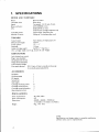
1. SPECIFICATIONS
M O T O RA N D T U R N T A B L E
Motor:
T u r n t a b l ed r i v e :
Speed:
W o w a n df l u t t e r :
S/N:
T u r n t a b l ep l a t t e r :
Momentof inertia:
DC servomotor
D i r e c td r i v e
Two sPeeds:33-113 rPm,45 rPm
0 . 0 3 %( W R M S )o r l e s s
6 8 d B ( D | N - B )o r m o r e
( w i t h P i o n e ecr a r t r i d g em o d e lP C - 1 3 5 )
3 2 1 m md i a m .a l u m i n u ma l l o y
24okg-cm2(includingrubbermat)
TONEARM
pipe arm
S-shaped,
Static-balance,
Tonearmtype:
221mm
E f f e c t i v ea r m l e n g t h :
'
+3"- -1
Track;:re
grror:
15.5mm
Overhang:
4 g ( m i n . )- 1 0 g ( m a x . )
weight:
U s a b l ec a r t r i d g e
(For cartridgeweighsover 8.5g, attach the sub weight)
SUBFUNCTIONS
Anti-skatingforce control
P l u g - i nt y p e h e a d s h e l l
Oil-dampedarm elevator
H inges( Free-adlustable)
Lateralbalanceweight
Fine speedadjusters (33-113 rpm, 45 rpm: usingthe stroboscope
f o r t u r n t a b l es p e e da d j u s t m e n t ) .
ACCESSORIES
Headshell
Overhanggauge
EP adaptor
Screwdriver
S u bw e i g h t
Cartridgemountingscrews
m o u n t i n gn u t s
Cartridge
Cartridgemountingwashers
O p e r a t i n gi n s t r u c t i o n s
1
1
1
1
1
6
2
2
1
MISCELLANEOUS
Powerrequirements:
P o w e rc o n s u m p t i o n :
Dimensions:
Weight:
ACrl 20V, 60Hz
5W
4 4 0 ( W )x 3 6 2 ( D )x 1 5 9 ( H ) m m
17 - s l 16 ( W )x 1 a ' 1l a ( D \ x 6 - 1 1 4 ( Hi )n .
8 k g , 17 l b 1 0 o z
NOTE:
Specificationsand design subject to possiblemodification
without notice, due to improuements.
4
a
2. PANEL F A CI LI T I E S
HeadshellStand
A spare headshell can be stored in this stand.
Align the headshellpins with the stand grooves
and insert.
Observethat the headshelllength is not greater
than the height of the dust cover. This stand can
also be used for storing the EP adaptor.
Stroboscope
Fine adjustments of rotation speed can be
performed with the aid of the stroboscope.
Adjust the SPEED ADJ. knobs while observing
the pattern indicated bellow. If the rotation is
fast, the pattern will appear to move toward
the left, while movement toward the right
indicates slow speed. Correct speed is obtained
when the pattern appears to be stationary.
Arm Rest
Supports the tonearm when not playing a record.
At the end of a playing session,engagethe clamp
as illustrated below.
"'o"
,ffio^*
U
50Hz
F
33-l/3 rpm .!'!ri!!!r!.!#l!i!rilt*
4.lFalrailtH'
g
60Hz
=""':"i:'-:--.'-+
IEF-
rfr.r.f
.r.!i!*F
----_
*ffi
***
TEEEI
EP Adaptor
Placeon center shaft when playing 45 rpm EP
records.
PL.51
C,A
33 SPEED ADJ. Knob
Use for fine adjustment of 33-1/3 rpm.
45 SPEED ADJ. Knob
Use for fine adjustment of 45 rpm.
33 SPEED Button
Depressto play 33-1/3 rpm records.
45 SPEED Button
Depress to play 45 rpm records.
Function Lever
This lever incorporates power switch and arm
elevation functions.
. OFF
AC power is cut off.
. ON-UP Power is turned ON. When set from
DOWN to this position, the tonearm is
raised.
. DOWN
Tonearm is gently lowered.
O PER ATION
1. Remove stylus cover.
2. Set function lever to ON-UP.
Strobe lamp lights and platter rotates.
3. DepressSPEED button (33 or 45) according
to type of record.
4. Employ SPEED ADJ. controls and stroboscope to adjust rotating speed (required only
once per listening session)
5. Disengage arm clamp and gently position the
tonearm over the desired portion of the
record.
6. Set function lever to DOWN.
Stylus will be gently lowered onto the record.
7. Adjust volune and tone controls of the stereo
amplifier as desired.
8. At the end of the record, or to interrupt the
record, set the function lever to ON-UP.
The stylus will be raised from the record.
9. Return tonearm to arm rest and engageclamp.
10. Set function lever to OFF. Power will be cut
off and strobe lamp extinguished.
11. It is advisable to replace the stylus cover for
protection whenever the tumtable is not in
use.
OPERATING PRECAUTIONS
a Keep stylus and records clean. Use a stylus brush
to clean the stylus and a good quality record
cleaner to clean the records each time before
and after playing.
a Avoid exerting unnecessary force on the tonearrn. When changing headshells, set the tonearm
in the arm rest and engage the clamp.
a Take care not to impart vibration to the tumtable while a record is playing. Record and
stylus can be damaged.
a Avoid placing more than 2 records on the
turntable platter while playing records.
1
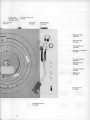
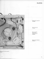
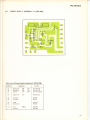
3. PARTS LOCATIONS
3.1
TOP VIEW
Outpul cord PDEO04(KCrl
PDE{!6 (K
Fubber grommet (A)
PEBOlO
AC power cord
KDG{I1
Hoadshellstand
PNW.073
Main panel
PNW-225
Strobo casesssembly
PXA-221
7
€'
Output cord
PDEOO4(KCT}
P D E O I 6( K U T )
AC power cord
KDG.O11
Rubbergrommet(B)
PEB.O11
Lateral bar
PLA.586
Lateral weight
K 14.438
Operation panel
PAN.O34
Counter weight
PXA-599
Antiskating knob
PAD.O09
Elevationarm assembly
PXA-598
Arm rest assembly
PXA-104
Variable resistor
PCS.005
Tonearmassembly
PPD.539
Button unit
PXT-036
2
T
Headshellassembly
PXA-630
e
Functionlever
PXT.035
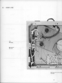
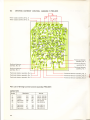
3.2
U N D E RV I E W
..4
@
,l
: ri tt
..-.
a
Y\J.-r
)s
PX T . 5 2 3
lvlicroswitch
K S F0 1 6
"i
;' ^' 'r c" !. h
').
't, 'l- \;i
,.",'i
D r v i n q c ur r e n t c o n t r o l a s s e m
PlVG OO7
I
Pf--E'lOA
Pow€rsupplyassernbly
B
nvB-{n6
Powertransformer
PTT.OI7
Motor (including
drive current
control assembly)
PXM{20
Powersupplyassembly
A
Pl,lrR€16
cuncntcontrolassembly
10
;,li:
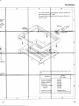
4 . EXPLODEDV$EW
;+
A rm restassembl Y
PXA-I04
iio
A rm restuni t
PXA-103
I
"l;
R ing
i.;.KAH-007
Tone
i PPD
Arm reststand
PLA-071
/ on*,
Rub b e rma t
>./
ii:51:i;::x:i',i; lli ;:!:ii i:i;:lq
:l tiii ::r I ::: l!: .:: :':
Operationpqnel
PAN-034 ,,-
,/
\ A
-
^-/
t/ /
7;8 l , _
,., .*r.*-1"i ,.
,=t'e-
fr
g
a' psAq fti|r o
./..t
Y
PowersupplyassembkB
(Seepase
PWR-0OO
4l
.,
"H,..
_
a
' s"
grV
V 1
g
V
i
v
Screw
a
r
.
b,
, . "e R gY{ i ':-/
Rubbercushion_-PEB-041 ,.'
P . C.B oardc l i p
KNK-186
. {I
/
I
,+- \
({
PXM-O20
Page
on 13
//'
+='..;,{:v{:'
"'6pffi>
\
Screw
PBA-006
\4'
sa'
-PowersupplyassemblyA
PWR-816
Te
KK
S
P
C
P
F
P
Screw
; 8
P B A -o19
i PSA4x6
Drivecurrentcontrol
ili
assemblyPWG-007
i'i
S P hol der
Powertra#former
PTT-017 .lti
cushion-.PNW-I51
l;
PEc_o1u
;;iilo'fi'"n
S
P
SP holder
PNW-133
SP holder
PNW-169
PBA-OO8
PSA3x20
12
NOT,E:
Part$r:indicated
in green cannot be supplied.
Hinge
PXA-108
Tonearmassembly
P P D- 539( Se ep a g e1 6 )
\----.
'Plate
N)
PNB-105
D ust-cover
a ssem bly
PXA-159
Screw
PBA-011
Terminal
K K C -011
F,ft.f;tg'l*'---qsqsmhi.il
R W 3 . 1x 1 3
l
PM3x10
I
e
R W 3 . 1x 1 3
L
Foot,*ssembly
PXA+55
Foot assemblv
pXA_109
\3x20
12
pM 3x25
PM3x25
3
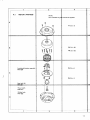
4.1
MOTOR (PXM-O2O)
4.
NOTE:
*i
Partsindicatedin gret*ncannotbe supplied.
Y
PT2.6x6
'r' ",+,'-.'-r ".f?..""i"..:rr$',
J{f-"J-iH{tiiriiT+$-t
{.
PM 2.6 x 20
P M 2.6 x 30
s"Iws,
IH
PM2.6xO
Locationaldetectorassembly
PWX-OO4
PM2.6x3
S te e lb a l l (B )
#
Thrust catch
P N W .O1
1
;
o
o
@
Rubberbuslr
PNT-OO2
$
ffi
, ti ,
!i'
,li!i
$
j i+ti;
lr!:"
;i!x,
_ f i
1rli
-j-
ffi
ff
ffi
ffi
PL-51
C'A
6
w
€
F U N C T I O NM E C H A SM ASSEMBLY
ffi
PSA3x20
F uc t i o nl e v e r
PXT-035
FW7
Microswitch
KSF-016
KCT model
w i th i n cover
A ngl e
PXT-034
B utton unit
PXT-036
PSA3x8
Lever
P NW- 091
EW.3
Varpble resistor
PCs005
13
4.3
ANTI SKATING ASS
BLY (PXA-641)
4.4
*P$-;S'1W
'qffi"F"S..W;ql
Arm base
PNW-542
El
Pf
E V le v e r
PXT.s17
Washer
PNB.519
E V ca m
PNW-544
EV sprins
Rt
Pf
g
E-2
PNW-547
AS lever
PNW-546
A S spri ng
P B H .O23
B i asl ever
PNW-545
FW -2.5
15
16
F'
!jgrt!
TONEARM ASSEMBIiY(PPD.539)
rl:llil
9t!)l
-:]t:I
:t9..,
f:i::
Elevation 4fr.hassem
b Iy
PXA-5e8ti$
1'f*e;'"F+#;*{;i{'-i*i[1i;1,ciii$6i8Hlif
]*l*iii;.€i;1,*;i*r#ali'3rit;t*l*r
tr6jn
I,4.\6
r--- - fll
Fiitl
t
Rubber
PNr-507
l::
,
i (
; \
[j,
rj
ErevationarmI K/
PNW'541
I\
Shaft
tu;
li
Lateral weight
KLA.438
iirr.:ffi
+ir \
s [s r 2 . 6 x 2
Lateralbar
, iLA;I8"6
E.Effi
Counterweight
PXA-599
l'q+
l++st
ex+)i
ffi
[email protected]
rH(
i.q.#
ffi
lgE
i@,k
ffi
#k
9^b
f*fl.
?.s.
ffi
q#,l
asi
t$i(
ts"G
_w;a
K+r
' l ' : . . , , :
d
1 6
, " - : l r : r t
'.$...e*etu
lh ut
xflaN-sor
2
4.5
PACKING
Operatinginstructions
P R 8-036
A
A
R ubbermat assembl y
P E A - 0 1 0( K U T m o d e l )
P E A -013(K C T model )
Y : :qf : : :
qi :E
litii iiii,
:;:: :t:.
FpdiiUUUIU-:
PHC-017
D ustcoverassembl y
PXA-159
45 rpm Adaptor
K N K .O55
Counterweightassembly
B
Case
PXA-599
P H N -OO5
Screwdriver
K E X -OO2
gauge
Overhang
PEC-012
Arm protector(L)
PHA-033
Side pad
PHA-023
Headshell
assembly
PXA€ffi
":
]
S ub w ei ght
PLA-563
C artri dgemounti ng
screw
K B A -045
F F W4
S i depad
P H A -023
c
Cartridgemounting screw
B1 1 - 6 5 7
C artri dgemounti ngw asher
Vinyl cover
H56-603
,;.
,F''3'tlQQ$,.-
rt ii.:l ij;l: i: :.:f:!:!t !r:ttr:trr s It li ii I ; ii .: :
:,:
:l:
Arm protector
P H A -032
(,n)
Cartridge mounti ngnut
871-653
Cartridge mounti ngscrew
KB4-044
Packingstopper
K N K .4O3
Packingcase
P H G - 1 2 5( K U T m o d e l )
P H G . I 2 6( K C T m o d e l )
TurntablepJatter
P N R -034 ;
D
C,A
PL.51
E F S C R E W S . W A S H E R SA N D
5 . N O M E N C L A T U RO
NU TS
The following symbols stand for screws, washersand nuts as shown in exploded view'
D€scription
Symbol
Symbol
Sh.pe
E r a z i e rh e a d t a p p i n g s c r e w
Ar-='t1
PT
Pan head tapping screw
fF---n
\t:
PTT
Specialscrew1A)
PTBA
S p e c i a ls c r e w ( B )
flflss$
Special screw {C)
IN
'.1t
WN
headtapping
Ovalcountersunk
F
PN
POTBA
ocr
Pan head machine screw
CM
ocM
EW
\l-_
E type washer
.{
SW
Spring lock washer
N
Nut
faced nut
Pushnut
Fiber flat washer
lll..-J
sc
D
I
F
BM
Binding head machine sc.ew
F
ocw
Oval countersunk head wood
OF
cw
Countersunk head wood screw
Gtr
PSF
Pan head screw with Ilat washer
G-
@ 4
@ i l
c E l
HS
Panheadscrewwith spring
lock washerand flat washer
@ E
@=
Slotted set screw (Flat point)
r
PSB
' 4 i l
\ r I
C
Truss h€ad machine screw
Pan head screw with spring
\
Slotted set screw (Cone point)
Tl\il
PSA
G > R
o I
Countersunkhead machine
Oval countersunk head
st'.pa
_DosctiPtion
Hexagon socket headless set
D
@ E D
Round head wood screw
EXAI\4PLE
PM. 3xB
h;:::;:t,,
Symbol
IH
i
F W ' 9 { x1 r
r
(E'l
1,-l r
-
in mm { I )
thickness
Ldiameterinmm(d)
j
+Symbol
._1.
--l'
6
.yl i
6. SCHEMATIC
6.1
AGRAM, P.C. BO
D PATTERNSAN
PA]
SCHEMATICDIAGR
PositionaL d
(PWX
assembLy
DrivinXcurrentrcon
t PWG- 00'1)
ll assembt,y
Q a ,Q 6, Q 1 2
2SB564xc
Q ' , Q rQ
, s,Qo,Qs,
25C94.5Pxe
D'-DrlN60x3
R2124'lKC610/16
19
eo
ERNSAN
PARTS LIST
I
..I
,!,r
:4
t;
,i.
**
s,ii
sr %nPrl
*
$
$
.di
t€
nt current/con
nbUy( PWG- 00'l )
IE
2SC?35
rsv
33xz
N
N
c.,
(t
d.
Qrr
i0't
v0r24
222x2
Raz4'l K
eo
Pq$rersuppty
asembLyA
( P w R- ' E t 6 )
r
PL-51ClA
6.2
POWERSUPPLYASSEMBLYB (PWR.OO6I
sf
cO
cO
zO
rO
fo
Og
aa a
ParBList of PowerSupplyAssemblyB (PWR-0{l6l
Symbol
cl
P.n No,
Daacription
qt
Electrolytic
Electrolytic
C6r.mic
33O
10O
O.01
R1
Carton film
3.3k
ol
q2
Taan3i3toa
Tramistor
250234
25C372
D1
D2
Diodo
Zonerdiode
PCX{10
voz.192
FU
Fu.e
Fulo clip
50OmA
35V
25V
sOV
cEA 331P35
cEA 101P25
CKDYFtO3Z50
e
RD7.PS
332J
PEK.{Xl4
K91{06
21
DRrvrNG CURRENTCONTROLASSEMBLY
(PWG.Oo7)
Powersupply asembly B No. 5
Powersupply assemblyB No. 6
Positionaldetector
assembly,
No. 7
Positionaldetector
asembly No. 6
Positionaldetector
assembly,No. I
Positional
assembly,No. 10
Positional
assembly,No,4
Positionaldetector asembly, No.
Positionaldetector assembly,No. 1
Positionaldetector assembly,No.
Positionaldetector assembly,No. 3
Positionaldetector assembly.No. I
Positionaldetector assembly,No. 8
PartsList of Driving Current Control Assembly(PWG-O071
CAPACITORS
Synbol
c1
c2
c3
c4
c5
c6
ca
Ir.|c.iction
Pa.t No,
Ef.ctrolvtic
Ef6ctrolyrh
2m
2,2
50v
50v
50v
6V
50v
El.ctrolvtic
Ef.ctrolyric
El.cr.olytic
10
47
100
16V
10v
25V
CKDYF103250
CKDYF103250
CKDYF103250
cEA 221P6
CEA 2R2P50
cEA 100Pt6
cEA 470P10
cEA 101P25
rPL.51clA
RESISTORS
Symbol
Description
Part No.
R201
R202
R203
R204
R205
Carbon film
Carbon film
Carbon f ilm
Carbon film
Carbon film
330
27O
330
27O
330
R D 7 4 V S3 3 1 J
R D 7 4 V S2 7 1 J
R D % V S3 3 1 J
R206
F.207
R208
R209
R 2 10
Carbon film
Carbon f ilm
Carbon f ilm
Carbon film
Carbon film
27O
2.2
180
3.3k
680
RD%VS 271J
R D % V S2 R 2 J
R D % V S1 8 1 J
RD7.VS332J
RD74VS681J
R211
R212
R213
R214
R 2 15
Carbon film
Carbon film
Carbon film
C a r b o nf i l m
C a r b o nf i l m
1Ok
47k
27k
5.1k
1.3k
RDy.VS1O3J
RDy.VS473J
RD74VS273J
R D % V S5 1 2 J
B Dy.VS 132J
R216
R217
R218
R219
R220
Carbon film
Carbon film
Carbon film
Carbon film
Carbon f ilm
680
6.8k
47O
27k
150
R D % V S6 8 1 J
RD'/.VS 682J
R D 7 . V S4 7 1 J
RD%VS 273J
R D % V S1 5 1 J
R221
R222
R223
R224
R225
Carbon film
Carbon film
Carbon film
Carbon film
Carbon film
56k
22k
2.7k
8.2k
39k
RD74VS563J
RD7.VS223J
RD%VS 272J
RD%VS A22J
RDI/4VS393J
R226
R227
R228
R229
R230
Carbon film
Carbon film
Carbon f ilm
Carbon film
Carbon film
|50
47k
15k
3.9k
12k
R D % V S1 5 1 J
R D % V S4 7 3 J
R D % V S1 5 3 J
RD/1VS392J
RDI/4VS123J
R231
R232
VRl
VR2
Carbon film
Carbon film
S e m i - fi x e d
S e m i - fi x e d
3.3k
3.3k
3.3k-B
4.7k-B
RD%VS332J
RDy.VS332J
PCP-001
PCP-002
RD%VS 331J
aD%vs 271J
Symbol
Description
Part No.
o6
Transistor
o7
Transistor
o8
Transistor
o9
Transistor
010
Transistor
011
Transistor
012
Transistor
013
ot4
015
Transistor
Transistor
Transistor
016
Transistor
017
o18
Transistor
Transistor
2SC71 -F
(25C923-E)
25C735-Y
25A733-O
D1
D2
o3
D4
D5
Diode
Diode
Diode
Varistor
Varistor
rN60
tN60
tN60
vD1222
vD1222
D6
D7
D8
D9
D10
Varistor
Varistor
Varistor
Zener diode
Varistor
vD1124
vD't124
vo1124
w2081
vD1222
Dl1
Varistor
vD1124
2SC71 -F
(2SC4s8-C,
2sc945-P1)
2SC711-F
(25C923-E)
2SA715-C
(2SA509-Y,
258564-Ll
2SC71 -F
{25C458-C,
2SC945-P1
)
2SC71-F
(2SC458-C,
2SC945-P1
l
2SC71 -F
(25C923-E)
2SA715-C
(25A509-Y,
258564-L)
25A733-O
2SC100G.8L
2SC1000-8L
SEMICONDUCTORS
Symbol
Description
ol
Transistor
a2
Transistor
o3
Transistor
o4
Transistor
o5
T r a n s i s t or
Part No.
2SC711-F
(2SC458-C,
2SC945-P1
)
2SC71 -F
(2SC458-C,
2SC945-P1
)
2 S C 71 - F
(2SCg23-El
2SA715-C
(2SA509-Y,
258564-Ll
25C711-F
(2SC458-C,
2SC945-P1
)
NOTE:
1 . Q , Q r , Q r , Q u , Q o , a n d Q , o s h o u l d , o n t h e s a m ec i r c u i t
board, use the same hind and ranh of product.
2. Qr, Qr, Qr, and Qru should, on the same circuitboard,
use the same hind and ranh of product.
3. Dt, D,, and D, should be'paired'(PYY-006-0).
-J
POSITIONALDETECTORASSEMBLY(PWX{'04)
DriviE curBnt controlarrombly,No. 2
orront control r3rambly, No. 8
Driving current contol
asornbly,No.I
Drivir€ @rrrnt control
ass€mbly,No. I
Driving qfiont control
.$embly, No.3
Driviq qlrrsnt colrtol
6s€rnbly, No. 6
Drivlru d.trrafit cortrol
ar.fflbl% No. 7
Driviq currcflt contol
!.c.tnbly, l'lo, 4
DriYirtrcurront control
ar€rnbly, l{o, l0
Drlvir|gcurrontcontrola:sembly,No. 5
ng.urront controla$6nrbly,No. 11
Part Lirt of Position l DstoctorA3$mbly (PIVX-{X!4I
ay|nbol
HI
H2
H3
R10r
Fro:l
nl00
RlO/r
24
Dasittbn
H.ll.tfLct alamrnt
H.lldt cr .tmrir
HllliitGt
dinmt
Crbo.r tlhn .olnor
C|rbon tilm raaittor
c.,boi fllm rlitior
C!.bon tilm roi.tor
P.n l{o.
Ik
tt
1k
3:tO
FCX{D1
FCX{Ol
PCX{nl
RDXPSI@J
RDI'PSIO2J
FONPSI(nJ
FDr{Ps3:,1J
PL-51C,A
.
I
6.5
POWERSUPPLYASSEMBLYA (PWR.816I
)
PartsList of PowerSupplyAssemblyA (pWR-816)
Symbol
D6!cription
c1
Myler
0.033
R,|
Metal oxide
10k
FU
Fuse
Fuseclip
3O0mA
Parl No.
KCEO09
2w
RS2P103J
E2rO30
Kg't {x)6
P5
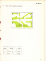
7. PXM.O2O OUTLINEOF OPERATION
i
III
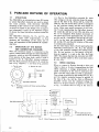
7.1
STRUCTURE
The PXM-020 is an external-rotor type DC motor
in which Hall-effect elements are used to detect
the rotor position, with electronic ON-OFF
switching of the current to the motor windings.
As shown in Figure 1a, the ferrite rotor is magnetized altemately N and S in 45' segments. Figure
1b shows the three Hall-effect elements under the
rotor.
The Hall-effect elements, H,, H2, and Hr, are
fitted 30" apart (120" magnetically), so that
whatever the orientation of the rotor, one of
them will experience a Hall potential at a particular time.
7.2
OPERATION OF THE MOTOR
(SEE CONNECTION DIAGRAM)
When the electrical supply is connected to the
motor, current flows through the three Hall-effect
elements, which go into the operating condition.
If we assume,at this time, that a rotor N pole is
located at the H, Hall-effect element position,
then the Hall potential developedin H, sendsthe
base of Q, negative (-) and that of ez positive
a Top of rotor
Fig. 1:
b Sectionof rotor
R e l a t i v eL o c a t i o n s o f R o t o r a n d H a l l - E f f e c t
E lements
(+). Due to this Hall-effect potential ez turns
ON, voltage at the Qz collector drops, the potentail on the base of Qq drops, and Qo tums ON.
With Q4 ON, the motor drive coil Wr is energized
by the collector current, and the rotor begins to
move. After some small movement of the rotor,
the N pole approaching the Hall-effect element
Hz causesQe and Qe to turn ON, and drive coil
We to be energized. With further movement of
the rotor the N pole approachesHs, Qro and erz
go ON, and Wz is energized.The first N pole passes H: as the next one approachesH1, putting
Qz and Qa ON, and thus the rotation of the rotor
is continuously sustained.
On the other hand, when a S pole approachesthe
Hall-effect element(s) H, (H,, H, ), the polarity
of the Hall potential changes, the base(s) of e1
(Qr, Qr) go positive (+), the base(s)of ez (eu,
Qro) go negative (-), and so Qz (Qe , Qro) tum
OFF. This meansthat Qr (Qa, Qrz)also tum OFF
and the current ceasesto flow in the drive coil(s)
w , ( w r ,w , ) .
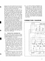
7.3
SPEED CONTROL
When no current is flowing through a drive coil
(that is when a S pole is approaching the Hall
effect element), a voltage proportional to the
speed of rotation of the rotor is induced in the
drive coil (the same effect as with a generator).
This voltage is rectified by the diode(s)Dr (D2,D3),
and the negative potential derived is applied to
the base of Q,o. Q,c and Q,, form a differential
amplifier circuit, and the standard voltage for
33-1/3 or 45 rpm rotation is applied to the base
of Qrr. It follows that so long as the rotor is
e
II
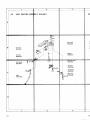
0
Locational
detector
section
Driving
cu rrent
control
section
Hall-effect elements
Standard
voltage
generator
section
D r i v ec o i l
M o v i n g( r o t a t i n g s) e c t i o no m o t o r
Fig.2:
B l o c k D i a g r a mo f t h e P X M - 0 2 0
Fine speedadjustment
c o n t r o l( 3 3 - 1 / 34, 5 r p m l
o
I
'l
turning at the correct speed (revs), this circuit is
balanced. If for any reason the speed of ratation
of the rotor exceeds the proper value, the voltage
generatedin each drive coil will increase.
This causes the potential on the base of Qrq to
drop, and the potential on the basesof Q1s and
Q13 rises. As the potential on the base of Qt.
rises, the collector current drops and this reduces
the potential on the base(s)of Q, (Qr, Qtt) .
This results in a reduction in the current flowing
through Qz (Qu, Q,o), and a rise in the potential
on the base(s) of Qo (Q., Qtr), so that the
collector cunent(s) of Qq (Qr, Qrr) drop. If the
collector current drops, the field strength of the
drive coil also drops, the rotor speed drops, and
it returns to the correct speed of rotation.
On the other hand, if the rate of rotation of the
rotor drops below its proper value, the processis
precisely the reverse of the above: the voltage
across each drive coil drops, and the base potential of Qre rises. This causesthe collector current
of Qr: to increase,and the current(s) through Qr
(Qr, Qtr) and Qz (Qu, Qto)alsorise.As the collector current(s) of Q, (Qu, Q,o) increase,the base
potential(s) on Qo (Qr, Q,r) drop, the collector
current(s) rise, the magnetic field strength of the
drive coil(s) increases, and the rotor speed increasesto the correct value.
7.4
TEMPERATURE COMPENSATION
The section which corrects the speed of rotation
of the motor as the ambient temperature changes
, r, Du, Dr, Ds, D1s,D11)
c o m p r i s e vs a r i s t o r s ( I ) 0D
to achievetemperature compensation.
Da compensatesQ3, Q7, and Qtr. If Do were
not provided, an increasein temperature would
be accompaniedby a drop in the Vs-B of Q3,
Qr, and Qri, and an increasein the collector
currents. This would result in a drop in the
base potentials of Qo, Qr, and Qrz, and an
increase in their collector currents with, in tum
a higher current through the drive coils and a
correspondingincreasein the speed of revolution. The temperature coefficient of D4
(VDl222) is -3.6mV/"C, which ensuresthat
1
the basesof Qr, Qr, ?hd Qtt do not drop in
potential, so that the motor speed will not increase.
D5 compensatesQ,u. If Ds were not provided,
an increase in temperature would cause an
increase in Qru collector current, and a corr e s p o n d i n gi n c r e a s ei n Q , o , Q , r , Q , r , Q , . , w i t h
a rise in the base potential of Q:, Qr, zrndQrr,
and an increasein the speedof the motor.
o Do, Dr and Ds provide the temperature compensation for rotor magnetism. Magnetic field
strength drops at -O.|8Vol"C with an increase
in temperature. For this reason,if Do, Dz and
De are not provided, even at the proper rate of
rotation, the voltage generated in the drive
coils would drop, because the comparator
would indicate that the speed has dropped,
and so the motor speed would. De (33-1/3)
Dz and Ds (45 rpm) raise the potential at the
base of Qrs as the temperature rises,preserving
the balance of Qr+ and Qrs, and maintaining
proper speed.
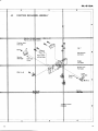
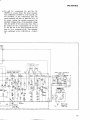
C O N N E C T I O ND I A G R A M
PositionaLdebect'o
( PWX-004
assembLv
flr- H3
PCX-OO1
03, Q1,Q1,01
Qa,06,Q12
2SB564xs
2SC923E
5
D , -D : l N 6 0 x 3
27
PL-51ClA
o Dro and Drr compensate Dg and Qur, Do
(W2081) is a zener diode. The zener temperature coefficient is 0.05Vo1"
C. If D'oand Drr ?r€
not provided, as the temperature rises the
zener potential will rise, so that the Vs -e of
Qrr drops, raising the emitter potential (the
standard voltage) of Qrr. If the standard voltage
rises, the speed of the motor also rises. This is
the reason for the compensation by Dro and
Dr r for the rise in Dg zener potential and the
drop in Vn-n potential of Qrz The temperature coefficient of Drr (VDl124) is -1.9mV/
oc.
orivinX currentr contrnoL
assenbt/ ( PWG- 00'1)
Q'r,Qrt
xA,?33x2
Q , . ,Q r s
25Cl000
xz
Dr,Dr
Voll24x2
PowerSuppLyassembL/B
(PwR-006)
i
0,25023,+ D,'0+
&
i_-_o: 2sslt
Qn
Qe
It,Qu,0,e
i923Ex+
D r ,D s
YDl222xz
8 . T R O U B L ES H O O T I N GC H A R T
8.1
M O T O R D O E SN O T T U R N
Is there 18V acrossterminals 4 and 5 of
the driving current control assembly?
Power supply circuit defective.
Is there 9.4V between the emitter of
Qtt and terminal 4?
Block 1 on the General Circuit
Diagram (page 27) is defective.
Is there 2.8V between terminals 4 and
72 (at 33-1/3 rpm)?
Check the connection to terminal 14.
Block 2 is defective.
Is the voltage between terminals 4 and
6, 8, or 10 (app. 8 - 9V) roughly
the same as that between terminals 4
and 7 (9 and l-1)?
Hall-effect element Ht (H, or H. ) is
defective.
With the power OFF, is the resistance
between terminals 4 and 1, 2, or 3
6415Cl? The plus (+) test lead should
be connected to terminal 4.
Motor wiring is defective.
High resistance;open circuit.
Low resistance:short.
Check each of the voltages in block
4. are the values incorrect?
29
8.2
W I D E V A R I A T I O N SI N M O T O RS P E E D
With the power ON, rotate
the tumtable slowly by
hand (about five secondsfor
each complete rev.). Do the
collector voltages of Q+,
Qe, and Q12cycle between
0 and 17V?
Is the voltage between terminals 4 and 6, 8, or 10
(app. 8 - 9V) roughly the
sarne as that between terminals4 attd 7 ,9, or 11?
With the power OFF, is the
resistance between terminal
4 and L, 2, or 3 equal to
6415(=l? The plus (+) test
lead should be connectedto
terminal 4.
Hall-effect element H, (H,
or H3 ) is defective.
NO
Motor wiring is defective.
High resistance; open circuit.
Low resistance:short.
YES
Disconnect the diodes of
block 5 (Dr , Dr, and D, )
and check them with a test
meter.
Are they conductive in forward direction. or non-conductive in backwards direction?
Check each of the voltages
in block 4.
Block 3 is defective.
Is the voltage acrossRro., on
block 3 approximately constant, without significant
change?
30
Shaft or bearingsdefective.
Defective diode.
Even if only one diode
proves to be defective, the
complete set of three should
be replaced.
PL.51clA
8.3
MOTOR RACES
Check the connections to terminals
12, L3, and 15.
Is the voltage between Q,a baseon the
driving current control assembly and
terminal 4 equal to 2.8V?
Block 2 is defective.
Block 3 is defective.
31
9. ADJUSTMENT
9.1
MOTOR SPEED
When it proves impossible to adjust the fine speed
controls to give the correct speeds,the motor may
be adjusted as follows.
1. Set the fine speed adjustment controls on the
stereo tumtable to their mechanical centers
(approx. in the middle).
2.The separatevolume-type controls on the p.C.
Board PWG-007 are accessiblefor both BB and
45 rpm adjustments. Use a small screwdriver to
tum these preset controls to give synchronization as indicated by the stroboscopic speed
indicator on the record player.
3. When even turning the controls fails to give
the required adjustment, refer to Connection
diagram on page 6, and change Rr23 (gg-1/g
rpm) and P"rrs (4b rpm) within the range
1.5k0 to 5.6k4 before repeating the adjustment.
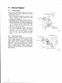
9.2
ARM ELEVATION
Tonearm elevation is operated by a cable release.
If the release stretches due to aging or other
reasons,loosen EV guide screw (Fig. 1) and adjust
cable release anchor condition. perform this
adjustment with tonearm elevation in DOWN
setting. As adjustment standard, EV lever unit
(Fig. 2) should tightly contact straight line
portion of EV cam. Be sure to confirm operation
after adjusting.
EV guide
Cablerelease
EV lever
EV cam
E V l e v e ru n i t
Fis.2
32
I
D I R E C TD R I V E
STEREO TURNTABLE
PLISIOA
HGT
Additional
I JoruicMnua,l
I
This leaflet provides the description of the parts
applied only HGT model.
For detailed instructions on adjustments,description, etc., please refer to the Service Manual of
PL-510A/KCT,KUT.
I
I
()rrIoNEER'
(HGT model)
1O. SPECIFICATIONS
M O T O RA N D T U R N T A B L E
Motor:
T u r n t a b l eD r i v e :
Speed:
Wow and flutter:
S/N:
T u r n t a b l ep l a t t e r :
Momentof inertia:
DC servomotor
D i r e c td r i v e
Two sPeeds:33-113 rPm,45 rPm
0.03%(WRMS)or less
6 S d B( D l N B ) o r m o r e
( w i t hP i o n e ecr a r t r i d g em o d e lP C - 1 3 5 )
3 2 1m m d i a m .a l u m i n u ma l l o y
24}kg-cm2(includingrubbermat)
TONEARM
S-shaped,
Static-balance,
PiPearm
Tonearmtype:
2
2
1
m
m
l
e
n
g
t
h
:
E f f e c t i v ea r m
+3o - 10
Trackingerror:
15.5mm
Overhang:
a
g ( M l N ) - 1 0 g( M A X )
w
e
i
g
h
t
:
U s a b l ec a r t r i d g e
(For cartridgesweightsover8.5g,attachthe sub weight)
For Use in United Kingdom onlY.
Pleasenote:
Models employ 3-conductor mains leads' Please
read the following instructionscarefully before
connecting.
WARNING: THIS APPARATUS MUST BE
EARTHED.
CAUTION 240V: MAINS SUPPLY VOLTAGE
IS FACTORY ADIUSTED
AT 24O VOLTS'
IMPORTANT
The wires in this mains lead are coloured in
a c c o r d a n c ew i t h f o l l o w i n g c o d e :
Earth
Green-and'Vellow:
Neutral
B lu e :
Brown:
SUBFUNCTIONS
Anti-skatingforce control
P l u g - i nt y p e h e a d s h e l l
Oil-dampedarm elevator
Hinges(Free-adjustable)
Lateralbalanceweight
Finespeedadjusters(33-113 rpm,45 rpm: usingthe stroboscope
for turntablesPeedadiustment)
ACCESSORIES
Headshell
Overhanggauge
45 rpm adaptor
Screwdriver
S u bw e i g h t
Cartridgemountingscrews
Cartridgemountingnuts
Cartridgemountingwashers
Operatinginstructions
1
I
Live
As the colours of the wires in the mains lead of
this apparatus may not conespond with the
coloured marhings identifying the terminals in
your plug proceed as follows.
The wire which is coloured green'and-yellow
must be connected to the terminal in the plug
which is marhed by the letter E or by the safety
earth symbot ! or coloured green or green-andyellow.
The wire which is coloured blue must be
connected to the terminal which is marhed with
the letter N or coloured blue or blach.
The wire which is coloured brown must be
connected to the terminat which is marhed with
the letter L or coloured brown or red.
I
I
6
2
2
1
MISCELLANEOUS
Powerrequirements:
P o w e rc o n s u m p t i o n :
Dimensions:
AC 220V,240Y , SOHz
7W
Weight:
8 k g ,1 7 l b 1 0 o z
x 159(H)mm
x 362(D)
440(W)
1a'1
x
17-sl1
6(w)
la(D\x 6-1/4(H)in.
NOTE:
Specifications and design subject to possible modifi'
cation without notice, due to improuements.
34
1 1 . E X P L O D E D rEW (HGT)
R u b b e rb u s h ( C )
PEB-038
NOTE:
Partsindicatedin greencannot be
.
..1
" S
Output cord
PDE-OO4
Y@'
./
.#*)\
Washer
_\--\ _
PNM-005
Micro switch
\
KSF-016
,\
FunctionmechanismassemblY
PowersupplyB assembly
--
PL - 51c l A
{l
The parts indicatedtfu designationand parts numberare
as H$[ model.
newly-employed
The parts without deffiriptionare the sameas the parts in
w
P S F 3 x15
PKP-014
g
assembly
lXii
:ii
tli
lli
;li
t:1!t:
!il!li
c
!l!i
1:f
;:di
iit:{
:191;
i1i:
T h e f o l l o w i n g p a r t s a r d l h h a n g e dt h e p a r t s n u m b e r a s s h o w n i n t h e
table.
Anti skating
Rubber mat
H e a d s h e l la s s e m b l y
P a c k i n gc a s e
Power supply
F u s e0 . 4 A
F u s ec l i P
Operatinginstructi
5C
]
PXA.641
PEA-013
PX4.63O
PHG-128
PWR-OO8
PEK-OOs
KKR.OOl
P R 8 - 0 3 9( E n g l i s h )
PRD-016 ( French/German)
36
12. SCHEMATIC DIAGRAM (HGT modetl
MS !l/i10d
\
J
3
E
o
>\
e
d
!
o
E
c
*:i
$Ee
"i
s!
'l
?F
z!
6
-o
d>
I
I
: o
6 0
9o
0 =
I C
o
\
.!s
O
6
=
o
@
z,
d
o
oo_
;q
o.3
AO
o-d
37
.J
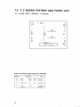
13. P. C BOARD PATTERNAND PARTS LIST
1 3 . 1 P O W E RS U P P L YA S S E M B L YA ( P W R - 8 1 8 )
oo
PT
o
o
Cr 0.033
r+{F-.<
o
o
PT
R1
r0K
(2W)
AC
Ca0033
o-_lF__-.€
o
o
PT
o
FUSE
3 1 5m A
o
o
o
sw2
o
PartsList of PowerSupply AssemblyA (PWR-818)
Symbol
a1
3A
Description
Part No,
c2
Myler
Myler
0.033
0.033
250V
250V
PCL-013
PCL-013
h l
M e t a lo x i d e
10k
2W
R S 2 P1 O 3 J
FU
Fuse
F u s ec l i p
315mA
KE K-OO8
KKR.OOl
PL-51clA
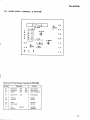
13.2 POWERSUPPLYASSEMBLYB (PWR-OO8)
Dr
o
o
?
so
6
4 o
*cr
+f 310135
F U r4 0 0 n A
PCI-0t0
a
Q,z?SC3?2
IN
o
o
ffi
Rr 3.3K
HAA-
o o
o g
I
o
+
7
o
T,,
|
100125
+FD5
WZ-192
Cr0.01
Hl<
6
o
3 o
2 o
qi 250234
4
l o
- o
+ o
PartsList of PowerSupplyAssemblyB (PWR-008)
Symbol
Description
Part No.
c1
c2
c3
Electrolytic
Electrolytic
Ceramic
330
100
0.01
R1
Carbonfilm
3.3k
o1
a2
Transistor
Transistor
25D234
25C372
D1
D2
Diode
Zenerdiode
PCXO10
wz-192
FU
Fuse
Fuseclip
4OOmA
35V
25V
50V
c E A 3 3 1P 3 5
c E A 1 0 1 P2 5
C K D Y F1 0 3 25 0
RD%PS332J
PEK-OOs
KKR-OO1
39
PIONEEFI
178
ELECTFIONIC
COFTPOFTATION
<1-1. Megu.o
1-Chome. Megu.o-ku, Tokyo 153, Japan
U.8. PIONEEFI
ELECTFICINICA
CctFTPOFTATION
75 oxfo.d
o. ve, Moonach,e,
New Je.sey
a7o74,u
s.A
(EUHoPEI
PIoNEEFI
ELECTFIoNIC
N.v,
LurrF agen-H€ven
3, 2O3O AnEwe.p, Etetg um
PIG,NEEFI
ELECTFIONICEI
AL'SITFTALIA
PTY. LTE!.
144 Bounda.y
Road, B.aesrde. V cto.ra 3195, Ausi.at a
c l\,lAY 1976
PnntedIn Japan