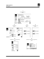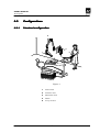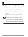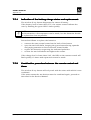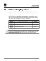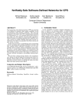
1
ENDOGRAPH DC 0051 User's Manual Version December 21, 2012 (Rev. 0) USER'S MANUAL Revision history Revision history Manual code 69599002 6959900203 Rev. Date Page 0 21.12.2012 - (Rev. 0) Description of the changes Document approval ENDOGRAPH DC USER'S MANUAL Revision history THIS PAGE IS INTENTIONALLY LEFT BLANK ENDOGRAPH DC (Rev. 0) USER'S MANUAL Contents Contents 1. INTRODUCTION 1.1 2. 1 Icons appearing in the manual ............................................................... 1 SAFETY INFORMATION 2.1 2 Warnings ................................................................................................ 3 2.1.1 2.1.2 2.1.3 Electromagnetic emissions................................................................... 4 Electromagnetic immunity................................................................... 5 Recommended separation distances to portable and mobile radio equipment ....................................................................... 7 2.2 Protection against radiation.................................................................... 8 2.3 Environmental risks and displacement................................................... 9 2.4 Symbols used ....................................................................................... 10 3. CLEANING AND DISINFECTION 11 4. DESCRIPTION 12 4.1 Identification plates .............................................................................. 12 4.2 Functions, models and versions ........................................................... 14 4.2.1 4.2.2 4.2.3 4.2.4 4.3 Configurations...................................................................................... 17 4.3.1 4.3.2 4.3.3 4.3.4 4.3.5 5. 6. High Frequency (HF) Generator.......................................................... 15 Extension arm and scissors arm ........................................................ 15 Tube-head......................................................................................... 16 Timer ................................................................................................ 16 Standard configuration...................................................................... 17 Remote timer configuration ............................................................... 18 Mobile stand configuration ................................................................ 19 Configuration with remote X-ray button............................................. 20 Configuration with wireless X-ray button ........................................... 21 TECHNICAL DATA 22 5.1 Method for measuring the technical factors.......................................... 25 5.2 Tube characteristic curves.................................................................... 26 5.3 Reference standards ............................................................................. 28 5.4 Dimensions .......................................................................................... 29 GENERAL INSTRUCTIONS FOR USE 6.1 Control panel - Description and functions ............................................ 30 6.1.1 6.1.2 6.1.3 6.1.4 (Rev. 0) 30 "Tooth anatomic selection" key........................................................... 32 “Increase/Decrease” key .................................................................... 32 "Select Size" key ................................................................................ 33 “Function” key (selection of receptor, cone presence and kV value)...... 34 i ENDOGRAPH DC USER'S MANUAL Contents 7. SYSTEM USE 7.1 Switching on the device ........................................................................ 36 7.2 Programmed/Manual exposure ............................................................ 37 7.2.1 7.2.2 Storing customised times ..................................................................... 41 7.4 Preparing the tube-head ....................................................................... 42 7.5 Exposure techniques ............................................................................ 46 Bisector technique ............................................................................ 46 Parallel technique ............................................................................. 48 7.6 Exposure with the supplied X-ray button ............................................. 49 7.7 Exposure with the wireless X-ray button (optional) .............................. 50 7.7.1 7.7.2 7.8 9. Performing a programmed exposure................................................... 38 Performing a manual exposure .......................................................... 40 7.3 7.5.1 7.5.2 8. 36 Indication of the battery charge status and replacement. ................... 51 Combination procedure between the remote control and timer ........... 51 Display of the number of exposures made ............................................ 52 ERROR MESSAGES ON THE DISPLAY 53 8.1 Fatal errors upon power-up and in the ready, idle and cooling statuses.................................................................................... 53 8.2 Fatal errors during X-ray emission ....................................................... 54 8.3 NON fatal errors.................................................................................... 55 CONTROL AND CORRECTION OF ANY ERRORS IN THE DENTAL X-RAYS 56 9.1 Typical defects of intra-oral X-rays ....................................................... 56 9.2 Typical defects caused by incorrect positioning .................................... 58 10. MAINTENANCE 59 No part of this publication may be reproduced, transmitted, transcribed or translated without the prior written consent of the manufacturer. This manual is the English translation of the original Italian manual version. ENDOGRAPH DC (Rev. 0) USER'S MANUAL Introduction 1. INTRODUCTION NOTE: This manual is updated for the product it is sold with, in order to guarantee an adequate reference to use the product properly and safely. The manual may not reflect changes to the product that do not affect operating modes or safety. The Endograph DC intra-oral X-ray unit takes high quality intra-oral Xrays thanks to reduced exposure times and the small dimensions of the focus spot. Endograph DC is intended exclusively for intra-oral X-rays. System operation is managed by a microprocessor, which permits high reproducibility of the exposure times. The system consists of the following parts: • timer: Endograph DC complete with the wall support • extension arm (30cm, 60 cm or 80cm for the wall version) • Scissors arm (DP) • Tube-head (60-65-70) kV ; 6 mA The aim of this manual is to instruct the user on the safe and effective use of the device. The device must be used in compliance with the procedures described, and never be used for purposes different from those herewith indicated. 1.1 Icons appearing in the manual manual This icon indicates a NOTE: please read the items marked by this icon thoroughly. This icon indicates a WARNING: the items marked by this icon refer to the safety aspects of the patient and/or the operator. (Rev. 0) 1 ENDOGRAPH DC USER'S MANUAL Safety information 2. SAFETY INFORMATION WARNING: Please read this chapter thoroughly. VILLA SISTEMI MEDICALI designs and builds the devices in compliance with the safety requirements; furthermore it supplies all information necessary for correct use, and the warnings related to danger associated with X-ray generating units. The manufacturer cannot be held responsible for: • use of Endograph DC equipment different from the purpose for which it was originally designed, • damage to the unit, the operator or the patient, caused both by incorrect installation and maintenance procedures different from those described in this user and service manuals supplied with the unit, and by wrong operations, • mechanical and/or electrical modifications performed during and after the installation, different from those described in the service manual. Only personnel authorised by the manufacturer may carry out technical operations on the unit. Only authorised personnel can remove the tube-head from its support and/or access the components under tension. ENDOGRAPH DC 2 (Rev. 0) USER'S MANUAL Safety information 2.1 Warnings The device must be used in compliance with the procedures described and never be used for purposes different from those herewith indicated. Before performing any maintenance operation, disconnect the unit from the power supply using the provided circuit breaker. Endograph DC is an electro-medical device and therefore it can be used only under the supervision of suitably qualified medical personnel, with the necessary knowledge on X-ray protection. The user is responsible for the fulfilment of the legal requirements regulating the ownership, installation and use of the equipment itself. Endograph DC has been built to support continuous operation at intermittent load; therefore please follow the described use cycles. Wherever necessary, use the appropriate accessories, such as the leaded aprons, to protect the patient from radiation. Endograph DC must be turned off when using electrosurgical devices or similar equipment near the unit. This device has not been designed to be used in environments where anaesthetic mixtures flammable with air, oxygen or nitrous oxide can be detected. In order to prevent risks of short-circuit and corrosion, avoid the entry of water or other liquids in the equipment. The parts of the unit that can come into contact with the patient must be cleaned regularly according to the instructions provided below in this document. WARNING: For safety reasons, it is prohibited to abnormally overload the extension arm or the scissors arm, for example by leaning on it. (Rev. 0) 3 ENDOGRAPH DC USER'S MANUAL Safety information 2.1.1 Electromagnetic emissions emissions In accordance with the IEC 60601-1-2 standard, Endograph DC is suitable for use in the electromagnetic environment specified below. The customer or user of the system must ensure that it is used in the said environment. Emissions test Conformity EMC environment of use RF emissions Class B Endograph DC is suitable for use in all domestic environments and in environments directly connected to the mains power supply at low voltage that supplies buildings for domestic use. Endograph DC uses RF power only for its internal functioning. As a result, its RF emissions are very low and most likely will not cause any interference in electronic devices located nearby. CISPR 11 Group I Harmonic emissions IEC 61000-3-2 Flicker/voltage fluctuation emissions IEC 61000-3-3 ENDOGRAPH DC Class A In compliance 4 (Rev. 0) USER'S MANUAL Safety information 2.1.2 Electromagnetic immunity In accordance with the IEC 60601-1-2 standard, Endograph DC is suitable for use in the electromagnetic environment described below. The customer or user of the system must ensure that it is used in the said environment. Immunity test Test level IEC 60601-1-2 Compliance level Electrostatic discharges (ESD) IEC 61000-4-2 ± 6 kV contact ± 8 kV in air ± 6 kV contact ± 8 kV in air Transients/sequence of rapid electric impulses IEC 61000-4-4 ± 2 kV for power supply lines ± 2 kV for power supply lines ± 1 kV for input/output lines ± 1 kV between phases ± 1 kV for input/output lines ± 1 kV between phases Overvoltages IEC 61000-4-5 EMC environment of use The flooring must be must be wood, concrete or ceramic tile. If the flooring is covered with synthetic material, the relative humidity must be at least 30%. The quality of the mains voltage must be the same as a typical commercial or hospital environment. The quality of the mains voltage must be the same as a typical ± 2 kV between phase ± 2 kV between phase commercial or hospital environment. and earth and earth Voltage dips, short 0 % Ut for 0.5 cycles 0 % Ut for 0.5 cycles The quality of the mains breaks and voltage 40 % Ut for 5 cycles 40 % Ut for 5 cycles voltage must be the 70 % Ut for 25 cycles 70 % Ut for 25 cycles same as a typical variations of the power supply feed 0 % Ut for 5 s 0 % Ut for 5 s commercial or hospital line IEC 61000-4-11 environment. If the Endograph DC user requires continuous operation during interruptions in the mains voltage, it is recommended to power the Endograph DC with an uninterrupted power supply or batteries. Magnetic field at the 3 A/m 3 A/m The levels of the main frequency magnetic fields at mains (50/60 Hz) frequency must be the IEC 61000-4-8 same as a typical commercial or hospital environment. Note: Ut is the a.c. mains voltage prior to the application of the test level. (Rev. 0) 5 ENDOGRAPH DC USER'S MANUAL Safety information Immunity test Test level IEC 60601-1-2 Compliance level EMC environment of use The RF portable and mobile communications units should not be used closer to any part of the Endograph DC, including cables, than the recommended separation distance calculated from the equation applicable to the frequency of the transmitter. Recommended separation distance: Radiated RF IEC 61000-4-3 Conducted RF IEC 61000-4-6 3 V/m from 80 MHz to 2.5 GHz 3V from 150 kHz to 80 MHz 3 V/m 3V d = 1.2 x √ P 800 MHz from 80 MHz to d = 2.3 x √ P 2.5 GHz from 800 MHz to d = 1.2 x √ P where "P" is the maximum rated output of the transmitter in watts (W) according to the transmitter manufacturer and "d" is the recommended separation distance in meters (m). The field strength of the fixed RF transmitters, determined by an on-site electromagnetic survey, should be lower than the compliance level in each frequency range. Interference may be verified near devices marked with the following symbol: ENDOGRAPH DC 6 (Rev. 0) USER'S MANUAL Safety information 2.1.3 Recommended separation distances to portable and mobile radio equipment Endograph DC is designed to operate in an electromagnetic environment in which radiated RF disturbances are controlled. The customer or user of the system can help prevent electromagnetic interference by ensuring a minimum distance between mobile and portable RF communication devices (transmitters) and Endograph DC as recommended in the following table in relation to the maximum output power of the radio devices. Maximum rated output power of the transmitter (W) Separation distance according to the frequency of the transmitter (m) from 150kHz to 80MHz d = 1.2 x √ P from 80MHz to 800MHz d = 1.2 x √ P from 800MHz to 2.5GHz d = 2.3 x √ P 0.01 0.12 0.12 0.23 0.1 0.38 0.38 0.73 1 1.2 1.2 2.3 10 3.8 3.8 7.3 100 12 12 23 For transmitters maximum rated output not shown in the table, the recommended separation distance "d" in meters (m), can be calculated using the equation applicable to the frequency of the transmitter, where "P" is the highest rated output of the transmitter in watts (W) according to the manufacturer of the transmitter. Note 1: at 80 MHz and 800 MHz, apply the separation distance for the higher frequency interval. Note 2: these guidelines may not apply to all situations. Electromagnetic propagation depends on the absorption and reflection of structures, objects and people. (Rev. 0) 7 ENDOGRAPH DC USER'S MANUAL Safety information 2.2 Protection against radiation radiation Although the dose supplied by modern X-ray units is quite low, the operator must adopt the precautions and/or suitable protection for the patient and himself according to current regulations, during the execution of radiography. WARNING: Protection against radiation is regulated according to law. The equipment may only be used by specialised personnel. a) The film (or the digital sensor) must be placed in the patient's mouth either manually or using the specific supports, and must be held in position by the patient if necessary. b) During exposure to the rays, the operator must not be in contact with the tube-head or the collimator cone. c) During exposure, the operator must maintain a certain distance from the source of the rays (at least 2 metres) in the opposite direction of the emission. d) During exposure, only the operator and the patient may be present in the room. e) Use the specific leaded aprons to reduce the undesired effect of secondary radiations for the patient. ENDOGRAPH DC 8 (Rev. 0) USER'S MANUAL Safety information 2.3 Environmental risks and displacement displacement Some of the device's components contain material and liquids that, at the end of the equipment life-cycle, must be disposed of at the recycling centres appointed by the local health units. In particular, the device contains the following materials and/or components: • • Tube-head: non biodegradable plastic materials, glass, dielectric oil, lead, tungsten, aluminium, copper. Other parts of the device: non biodegradable plastic materials, metal materials, printed circuits, iron-plastic materials. INFORMATION TO USERS IN THE EUROPEAN COMMUNITY: According to art. 13 of Legislative Decree 25th July 2005, nr. 151 "Implementation of Directives 2002/95/EC, 2002/96/EC, and 2003/108/EC, regulating the reduction of the use of hazardous substances in electrical and electronic equipment, as well as the waste disposal" The symbol with the waste bin crossed on the equipment or its packaging, indicates that the product must be separately collected from other waste at the end of its life. The separate collection of the present equipment that has reached the end of its life is organised and managed by the manufacturer. The user who wishes to dispose of this equipment must contact the manufacturer and follow their system to enable the separate collection of the equipment at the end of its life. Suitable separate waste collection for the subsequent start of the equipment discarded for recycling, for treatment and for environmentally friendly disposal, contributes in preventing possible adverse effects on the environment and health and promotes the reuse and/or recycling of materials of which the equipment is comprised. Illegal disposal of the product by the holder implies the application of administrative sanctions provided by law (Rev. 0) 9 ENDOGRAPH DC USER'S MANUAL Safety information 2.4 Symbols used In this manual and on the Endograph DC itself, apart from the symbols indicated on the keypad, also the following icons are used (see Chapter 6): Symbol Description Device with type B applied parts In some of its parts, the device contains materials and liquids that, at the end of the lifespan of the unit, must be disposed of at the appropriate disposal centres ∼ Alternating Current N Connection point to the neutral conductor L Connection point to the line conductor Earth protection Operation earthing OFF; device not connected to the mains ON; device connected to the mains Exposure enabling key; the exposure enabled status is indicated by the switching on of the corresponding green symbol Ray Emission Focus spot according to IEC 336 Warning: see the accompanying documentation Product identification code Serial number Date of manufacture (year and month) Manufacturer's name and address Filtration Tube-head X-ray tube 0051 ENDOGRAPH DC Conformity to the EC 93/42 Directive and subsequent amendments and additions (subsequent amendments and additions) 10 (Rev. 0) USER'S MANUAL Cleaning and disinfection 3. CLEANING AND DISINFECTION DISINFECTION In order to guarantee a good level of hygiene and cleaning, it is necessary to respect the following procedures: • Before starting any cleaning operation, disconnect the unit from the mains using the main line switch that must be foreseen during the installation phase. This manoeuvre is necessary because some parts inside the unit are still live even after it was turned off using the power switch. • Make sure water or other liquids do not penetrate inside the unit in order to prevent short circuits or corrosion. • Never use corrosive or abrasive substances (alcohol, petrol, trichloroethylene) to clean the unit. External surfaces Use a soft cloth and for more effective cleaning, use neutral soap and be careful not to damage the painted surfaces. During cleaning operations, make sure that the detergent and/or liquids do not enter inside the unit or remain on the painted surfaces. Parts in contact with the patient's skin To ensure the hygiene of these parts, they should be periodically disinfected with a 2% glutaraldehyde solution. (Rev. 0) 11 ENDOGRAPH DC USER'S MANUAL Description 4. DESCRIPTION 4.1 Identification Identification plates 3 2 4 1 ENDOGRAPH DC 12 (Rev. 0) USER'S MANUAL Description 1 Endograph DC plate (Rev. 0) 2 3 4 Tube-head plate DP arm plate Extension arm plate 5 6 Collimator 30 cm (optional) plate Wireless RX button (optional) plate 13 ENDOGRAPH DC USER'S MANUAL Description 4.2 Functions, models and and versions The Endograph DC intra-oral X-ray unit makes it possible to obtain consistently high quality X-rays thanks to the reproducibility of the unit parameters with very short exposure times and a very small focus spot. The Endograph DC intra-oral X-ray unit is compatible for being combined with digital image acquisition systems, thereby obtaining the maximum benefits of today's digital intra-oral radiologic technology. If you do not currently have a digital system, the use of high-speed film or film in the EKTRASPEED (Kodak) category is recommended in order to limit the dose absorbed by the patient. A button on the control keypad is used to select the operating mode and it is possible to select films with different speeds (sensitivity), the phosphor sensor, the digital sensor or a customised user mode "Custom mode". The Endograph DC X-ray unit has an LCD display with dimensions of 84mm x 45mm (240x128 pixel) which makes it easier for the operator to perform all operations, guaranteeing the immediate and complete display of the exposure parameters. The Endograph DC system can use the optional 30 cm collimator cone (to be ordered separately with code 61XXXXXX). The "long cone inserted" selection is signalled by the specific symbol on the display. In this configuration, the exposure times that were pre-set in the anatomic selection are automatically increased by a multiplicative factor of 2. The Endograph DC system includes the following: generator, tube-head complete with collimator, CPU (or logic) card that controls the system functions, keypad, extension arm and scissors arm. WARNING: The Endograph DC system does not automatically detect the presence of a cone or other item: the operator is responsible for checking the congruity between the indication on the display and the actual situation of use. ENDOGRAPH DC 14 (Rev. 0) USER'S MANUAL Description 4.2.1 High Frequency (HF) Generator The remote controlled HF generator, together with the tube-head, uses state-of-the-art microelectronic technology to obtain optimal quality Xrays while reducing the patient dose of rays. Conventional systems generally use the intrinsic capacity of the RX generator tube to conduct the electric current in one direction only. This generates a "train" of RX impulses. The Endograph DC unit instead uses constant-voltage technology that generates continuous and stable emission of X-rays. This reduces the emission of soft rays, guaranteeing the constancy of the emission parameters, kVp and mA. The microprocessor-based control ensures constant and repeatable exposure times; by simply pressing a button it is possible to automatically select the exposure times based on the size of the patient and the selected tooth. 4.2.2 Extension arm and scissors arm This consists of an arm with a double joint, which permits horizontal and upward extension. The tube-head remains balanced in all positions. NOTE: The scissors arm was designed to work correctly with a maximum opening angle of 160°; therefore, an opening angle of less than 160° is required for its use. A horizontal extension arm can also be added, which is available in different sizes (30 / 60 / 80 cm) to satisfy all requirements. (Rev. 0) 15 ENDOGRAPH DC USER'S MANUAL Description 4.2.3 TubeTube-head The tube-head makes it possible to select one of three different high voltage values: 60 / 65 / 70 kVp. The radiogenic unit is equipped with a collimator with a focus skin distance of 20 cm and a ray emission diameter of 6 cm at the cone exit. The tube-head is connected to the arm by a guide, which permits 390° horizontal rotation and 290° vertical rotation. 4.2.4 Timer The timer consists of an LCD display (240x128 pixel), two LEDs (yellow: X-rays in progress– green: ready for X-rays) and 5 buttons that are used to select from among 3 different patient sizes, 3 types of sensors (film, phosphor or digital) and 7 different pre-set anatomical structures (incisor, canine, premolar, lower molar, upper molar, front bite-wing and rear bite-wing). There are 36 fixed times available for manual selection which vary from a minimum of 0.01 seconds up to a maximum of 2 seconds. The timing is managed in order to guarantee exact precision of the exposure times. NOTE: The configuration can be set using the remote X-ray control outside the examination room. This consists of a wall support onto which the X-ray button is connected with an extendable cable. NOTE: The unit provides two separate contacts for the possible connection with external signalling devices. One contact signals the status of the unit as operative and ready to be used, the second emits the X-rays. The connection methods and the requirements necessary for the signalling devices are described in the "Service Manual". ENDOGRAPH DC 16 (Rev. 0) USER'S MANUAL Description 4.3 Configurations 4.3.1 Standard configuration 2 4 5 1 3 Figure 1 (Rev. 0) 1 Tube-head 2 Scissors arm 3 Extension arm 4 Timer 5 X-ray button 17 ENDOGRAPH DC USER'S MANUAL Description 4.3.2 Remote timer configuration 2 1 4 5 3 6 Figure 2 ENDOGRAPH DC 1 Tube-head 2 Scissors arm 3 Extension arm 4 Wall support 5 Remote timer 6 X-ray button 18 (Rev. 0) USER'S MANUAL Description 4.3.3 Mobile stand configuration 2 5 3 1 4 Figure 3 (Rev. 0) 1 Tube-head 2 Scissors arm 3 Stand 4 Timer 5 X-ray button 19 ENDOGRAPH DC USER'S MANUAL Description 4.3.4 Configuration with remote XX-ray button 1 Figure 4 1 ENDOGRAPH DC Remote X-ray button (optional) 20 (Rev. 0) USER'S MANUAL Description 4.3.5 Configuration with wireless XX-ray button 1 Figure 5 1 (Rev. 0) Wireless X-ray button (optional) 21 ENDOGRAPH DC USER'S MANUAL Technical data 5. TECHNICAL DATA Technical characteristics Equipment Endograph DC Manufacturer VILLA SISTEMI MEDICALI Buccinasco (MI) Italia Class Class I with type B applied parts (according to EN 60601-1 classification) Protection degree IPX0 standard device Line voltage 99-264 V∼ Rated voltage 110-240 V∼ Line frequency 50 / 60 Hz Maximum line current 5.2 A rms impulsive 2.5 A rms impulsive @ 115 V ∼ @ 230 V ∼ Technical factors for maximum line current 70kV, 6mA Absorbed power Maximum apparent line resistance 583W (584VA) 566W (570VA) 0.4 Ω (99-132 V∼) Mains fuse 0.8 Ω (198-264 V∼) 6.3 AT Selectable times from 0.01 to 2.00 s in 36 steps Automatic selection 882 pre-programmed times (7 anatomic 3 sizes - 3kV - 2 SID- 3 receptors) Time accuracy ± 5 % ± 2 ms High voltage values 60-65-70 kVp selectable Tubehead current 6 mA kV accuracy ± 8 % @ rated voltage Tubehead anodic current accuracy ± 10 % @ rated voltage Maximum exposure time 2.0 s Timer size 284×253×123.3 mm ENDOGRAPH DC 22 (Rev. 0) USER'S MANUAL Technical data Tube-head characteristics Manufacturer CEI Bologna (Italy) Rated voltage 60-65-70 kVp (selectable) Tubehead power 420 W Total filtration ≥ 2.5 mm Al eq. @ 70 kV HVL (Half value Layers) > 2 mm Al eq. Transformer insulation Oil bath Interval between the exposures / duty cycle 60 times the X-ray time/ 1 : 60 Focus size 0.5 (IEC 336) Minimum focus to skin distance 20 cm (optional 30 cm cone) X-ray diameter (@ 20cm focus) ≤ 6 cm (35x45 mm + 25x35 mm + 20x30 mm optional) Cooling Convection Leakage radiation at 1 metre < 0.25 mGy/h Technical factors for leakage radiation 70 kV, 6 mA, 1 s duty cycle 1 exposure every 60 seconds X-ray tube characteristics Manufacturer CEI Bologna (Italy) Type OX/70-5 Inherent filtration 0.5 mm Al equivalent to 70 kV Anode tilt angle 19° Anode material Tungsten Rated voltage 60-65-70 kV (selectable) Filament max voltage 3.1 V Filament max current 2A Anode thermal capacity 7 kJ Anode cooling capacity (max) 110 W (Rev. 0) 23 ENDOGRAPH DC USER'S MANUAL Technical data Environmental conditions Operating temperature range +10°C ÷ +40°C Relative working humidity (RH) range 30% ÷ 75% Temperature range for transport and storing -20°C ÷ +70°C Humidity range for transport and storing <95 % non-condensing Minimum atmospheric pressure for storing and transport 630hPa Weight of the unit and the removable parts Gross weight including packaging 30 kg Net weight of the unit in the standard configuration 23 kg Extension arm 60 cm (standard) 2.9 kg Extension arm 80 cm 3.5 kg Extension arm 30 cm 1.9 kg Scissors arm with tube-head support 10 kg Timer + wall support 5.05 kg Tube-head 5 kg ENDOGRAPH DC 24 (Rev. 0) USER'S MANUAL Technical data 5.1 Method for measuring the technical factors The measuring method with non-invasive instruments, for example kVp/t meter, is accepted, even if it generally provides less accuracy. In fact, the measurement of the high voltage at the tube with non-invasive instruments is closely correlated to the method selected by the instrument manufacturer; in general, this method is more inaccurate than the direct method and may also require two subsequent exposures. In the same way, the method of measuring the anodic current with the indirect method is affected by systematic errors, as they are often based on the measurement of the current/time product, dividing the measurement by the time measured with the said method. • High voltage value at the tube (kVp) The kVp value is defined as the stationary value of the high voltage applied at the tube that is stabilised under load after the pre-heating time. Measure the value of the kVp with a non-invasive instrument (with 2% accuracy), setting the exposure time to 1 second. • Measuring the exposure time The exposure time must be measured using a non-invasive instrument. In compliance with standard IEC 60601-2-7, the exposure time is measured as the interval of time between the moment in which the high voltage has reached for the first time a value equal to 75% of the peak value and the moment in which it goes down below this value. (Rev. 0) 25 ENDOGRAPH DC USER'S MANUAL Technical data 5.2 Tube characteristic curves OX/70-5 Emission characteristics Filament characteristics Load ENDOGRAPH DC 26 (Rev. 0) USER'S MANUAL Technical data Anode cooling curve Curv a Tube-head raffre ddame nto monoblocco cooling curve 90 80 70 E [kJ] 60 50 40 30 20 10 0 0 100 200 300 400 Time [min] (Rev. 0) 27 ENDOGRAPH DC USER'S MANUAL Technical data 5.3 Reference standards Endograph DC complies with the following standards: IEC 60601-1:1988 + A1:1991 + A2:1995 Medical Electrical Equipment – Part 1: General requirements for safety. IEC 60601-1-6:2004 Medical electrical equipment - Part 1: General requirements for safety collateral standard: Usability. IEC 60601-1-2:2001+ A1 Electromagnetic Compatibility Requirements and Tests. IEC 60601-1-3:1994 Gen. Requirements for Radiation Protection in Diagnostic X-ray Equipment. IEC 60601-2-7:1998 Particular requirements for the safety of high-voltage generators of diagnostic X-ray generators. IEC 60601-2-28:1993 Particular requirements for the safety of X-ray source assemblies and X-ray tube assemblies for medical diagnosis. IEC 62304:2006 + Ac:2008 Medical device software - Software life-cycle processes. ETSI EN 300 220-2 v.2.3.1 ETSI EN 301 489-3 v.1.4.1 Electromagnetic Compatibility and Radio Spectrum matters (ERM). ISO 14971:2007 Medical Devices - Application of Risk Management to Medical Devices. 0051 Guarantees Endograph DC compliance with Directive 93/42 and as amended. (subsequent amendments and additions) CAN/CSA C22.2 No. 601.1-M90 (2nd edition) +A1 + A2 Medical Electrical Equipment - Part 1: General Requirements for Basic Safety and Essential Performance UL 60601-1 (1st edition) Medical Electrical Equipment - Part 1: General Requirements for Safety ENDOGRAPH DC 28 (Rev. 0) USER'S MANUAL Technical data 5.4 Dimensions 30 0 30 FRONT VIEW Figure 6: Dimensions of the wall version 30 0 30 30 0 30 30 0 30 Figure 7: Dimensions of the mobile stand version (Rev. 0) 29 ENDOGRAPH DC USER'S MANUAL General instructions for use 6. GENERAL INSTRUCTIONS FOR USE 6.1 Control panel - Description and functions The Endograph DC control panel is divided into function areas, plus a display to view the operative messages and error signals. The following figure shows a general view of the control panel, while details on each functional area are provided in the following pages. LCD messages display "Select Size" key "Function" key "Decrease" key "Increase" key "X-rays in progress" luminous selection "Ready for X-rays" luminous selection "Tooth anatomic selection" key Figure 8: Endograph DC control keypad ENDOGRAPH DC 30 (Rev. 0) USER'S MANUAL General instructions for use The following figure shows the LCD display; details of every function area are shown on the following pages. "Tooth anatomic structure" indication "kV values" indication "Patient size" indication Type of receptor indication "Exposure time" indication "Dose" indication Figure 9: LCD display (Rev. 0) 31 ENDOGRAPH DC USER'S MANUAL General instructions for use 6.1.1 "Tooth anatomic selection" key Press the "Tooth anatomic selection" key to select in rotation from among the exposure times pre-set for the various teeth. It is possible to select from among seven different anatomic structures and the selection is shown on the display: (Lower) (Upper) (Rear) (Front) 6.1.2 “Increase/Decrease” “Increase/Decrease” key The "Increase" or "Decrease" keys are used to scroll the different selections in the menus or to manually change the exposure times. ENDOGRAPH DC 32 (Rev. 0) USER'S MANUAL General instructions for use 6.1.3 "Select Size" key Press the "Select size" key to select in rotation from among the the different patient sizes: small, medium and large. Also in this case the exposure times will change. An acoustic signal is emitted each time a key is pressed and the selected size will be displayed. (Rev. 0) 33 ENDOGRAPH DC USER'S MANUAL General instructions for use 6.1.4 “Function” key (selection (selection of receptor, cone presence and kV value) Using the "Function" key it is possible to select: − − an image receptor the presence of the long cone (SID 30 cm) − the value of kV applied to the tube. 1. Press the "Function" key: the receptor icon will start to flash. 2. Use the "Increase" and "Decrease" keys to select the type of receptor, from among: − Film − Phosphor − Digital . 3. Confirm the selection by pressing the "Function" key; the icon indicating the presence of the long cone will start to flash (SID 30 cm) . 4. Use the "Increase" and "Decrease" keys to select the presence ( ) or absence ( ) of the cone. 5. Confirm the selection by pressing the "Function" key. NOTE: If the cone is not present, the relative icon will not appear on the display. 6. The value of kV applied to the tube will start to flash. 7. Use the "Increase" and "Decrease" keys to select the required value (60 kV / 65 kV / 70 kV). ENDOGRAPH DC 34 (Rev. 0) USER'S MANUAL General instructions for use 8. Confirm the selection by pressing the "Function" key. NOTE: As the setting menu is cyclic, it will return to point 1 (receptor type selection). 9. To exit the setting menu, hold down the "Function" key for approx. 2 s. The system will return to the ready for X-ray state. (Rev. 0) 35 ENDOGRAPH DC USER'S MANUAL System use 7. SYSTEM USE 7.1 Switching Switching on the device Press the power switch located on the right side of the timer cover. This will start the "CHECK" function, which is indicated by an acoustic signal and the turning on of the LEDS and the display. When the "CHECK" function is complete, the machine will position itself by default in the configuration corresponding to the last selection made. The unit is now ready for X-rays. NOTE: • The ready for X-rays condition is signalled by the switching on of the relative green LED. • The ready for X-rays condition remains for a set period of time (variable during the installation phase: default 2 minutes), after this period of time has passed, this status will be disabled and pressing the exposure button will not emit rays. The brightness of the display will also be reduced. • To return to the ready for X-rays status, the device must be "woken up" by pressing any key (except for the X-ray button). ENDOGRAPH DC 36 (Rev. 0) USER'S MANUAL System use 7.2 Programmed/Manual exposure The operator can select between working with a programmed (anatomic) selection, that is with values set by the manufacturer based on the size and type of tooth, or perform an examination in manual mode, where it is possible to change the set times. With the programmed (anatomic) selection, it is possible to select the type of receptor used (different types of film, phosphor and digital sensors), the size of the patient and the kV value. (Rev. 0) 37 ENDOGRAPH DC USER'S MANUAL System use 7.2.1 Performing a programmed exposure If the previous examination was carried out in manual exposure mode, press one of the size selection or anatomic selection keys to switch to programmed exposure mode. In programmed mode it is possible to change the size, type of tooth and kV value. Each time the "Size selection" key is pressed , indicated acoustically, the Large patient / Normal patient / Small patient selection changes. To change the selection of the type of tooth, use the "Tooth anatomic selection" key . Each time this key is pressed the selection of the type of tooth changes in rotation. This is signalled acoustically and shown on the display. Based on the type of film that is selected, the pre-set times are provided in Table 1. Film (F) Size Small Normal Large Incisor 0.08 0.12 0.15 Canine 0.08 0.12 0.15 Premolar 0.10 0.15 0.20 Lower molar 0.12 0.18 0.24 Upper molar 0.15 0.22 0.30 Front bite-wing 0.08 0.12 0.15 Rear bite-wing 0.15 0.22 0.30 Table 1 NOTES: These values are related to film type F. The Endograph DC system can be programmed to use film with different sensitivity levels; the programmed times vary depending on the film's multiplicative factor. It is possible to request this setting from the technician during installation. ENDOGRAPH DC 38 (Rev. 0) USER'S MANUAL System use If digital radiography is selected, the exposure times are indicated in Table 2. Digital sensor Size Small Normal Large Incisor 0.05 0.05 0.08 Canine 0.05 0.05 0.08 Premolar 0.06 0.06 0.09 Lower molar 0.08 0.08 0.12 Upper molar 0.10 0.10 0.15 Front bite-wing 0.05 0.05 0.08 Rear bite-wing 0.10 0.10 0.15 Table 2 The times for permanent phosphor sensors are provided in Table 3. Permanent phosphors Size Small Normal Large Incisor 0.10 0.10 0.16 Canine 0.10 0.10 0.16 Premolar 0.12 0.12 0.18 Lower molar 0.16 0.16 0.24 Upper molar 0.20 0.20 0.30 Front bite-wing 0.10 0.10 0.16 Rear bite-wing 0.20 0.20 0.30 Table 3 NOTE: The times indicated in the tables are relative to the selection 65kV. The times for the 60kV selection are obtained by multiplying the values in the 65kV table by 1.45; they are multiplied by 0.7 for the 70kV selection. NOTE: The times indicated in the tables are those set by the manufacturer. These values can be changed as described in paragraph 7.3. A service technician is required to reset the default times. (Rev. 0) 39 ENDOGRAPH DC USER'S MANUAL System use 7.2.2 Performing a manual exposure Endograph DC makes it possible to work not only using the programmed mode described above, but also using the manual function. To access the manual function, press one of the two keys "Increase" or "Decrease" : the size icon will flash. The display will show the last time value selected in automatic mode; to change it, simply use the "Decrease" or "Increase" keys until reaching the desired value. The single variation of the time is signalled by an acoustic message; it is also possible to quickly change the exposure time (4 units per second) by holding down one of the "Increase" or "Decrease" keys for more than 2 seconds. NOTE: There are 36 times that can be selected manually and range from a minimum of 0.01 s up to a maximum of 2.00 s according to the following table: 0.01; 0.02; 0.03; 0.04; 0.05; 0.06; 0.07; 0.08; 0.09; 0.10; 0.11; 0.12; 0.14; 0.16; 0.18; 0.20; 0.22; 0.25; 0.28; 0.32; 0.36; 0.40; 0.45; 0.50; 0.56; 0.63; 0.71; 0.80; 0.90; 1.00; 1.10; 1.25; 1.40; 1.60; 1.80; 2.00 Table 4: Manual exposure times To return to the automatic time selection, press one of the "Size selection" ENDOGRAPH DC or "Tooth automatic selection" 40 keys. (Rev. 0) USER'S MANUAL System use 7.3 Storing customised times Endograph DC makes it possible to customise the programmed exposure times in order to adapt them to the user's actual conditions of use. Proceed as follows to store the customised times: 1. Use the "Increase" and "Decrease" keys to select the required value. 2. Hold down the "Function" key until an acoustic signal is emitted: a screen with the request to confirm or cancel the change will appear. 3. Press the "Increase" key to confirm or the "Decrease" key to cancel the change. NOTE: The stored time is related to the size, the tooth, the type of receptor and the kV value shown on the display at that moment. If the long cone is selected, some time values may be approximate. (Rev. 0) 41 ENDOGRAPH DC USER'S MANUAL System use 7.4 Preparing the tubetube-head 1. Position the tube-head with an angle suitable for the exposure and positioning required (see Figure 10, Figure 11, Figure 12, Figure 13). 2. Introduce the image receptor in the patient's mouth according to the selected technique (bisector or parallel). In this regard, see paragraph 7.5. 3. Move the tube-head cone towards the patient and direct it exactly towards the tooth to be X-rayed, referring to the following figures. NOTE: If you want to use the rectangular collimator, apply it to the end of the tube-head cone, positioning it as needed. NOTE: If you want to use the 30 cm extension cone, apply it to the end of the tube-head's 20 cm cone. WARNING: If the 30 cm extension cone is applied, the pre-set exposure times will be automatically doubled in order to obtain the same radiographic result. ENDOGRAPH DC 42 (Rev. 0) USER'S MANUAL System use MANDIBLE -15° -15° INCISIVI incisors incisives CANINI canines canines -5° -10° PREMOLARI premolars prémolaires MOLARI molars molaires Figure 10 (Rev. 0) 43 ENDOGRAPH DC USER'S MANUAL System use MAXILLA +40° +40° INCISIVI incisors incisives CANINI canines canines +30° +20° PREMOLARI premolars prémolaires MOLARI molars molaires Figure 11 ENDOGRAPH DC 44 (Rev. 0) USER'S MANUAL System use OCCLUSAL +65° 0° MASCELLA upper jaw machoire MANDIBOLA lower jaw mandibule Figure 12 BITE WING film rc 0° rc = RAGGIO CENTRALE main beam rayon central Figure 13 (Rev. 0) 45 ENDOGRAPH DC USER'S MANUAL System use 7.5 Exposure techniques This paragraph describes the various techniques used in general for intra-oral exposure. 7.5.1 Bisector technique Incidence of the X-ray beam - vertical angle In order to obtain a real image of the tooth, the ray must be perpendicular to the bisector of the angle formed by the longitudinal axis of the tooth and by the film. After positioning the X-ray beam and the patient's head based on these criteria, an average vertical incidence can be applied for each area. The incidence angle of the X-ray beam can be correctly measured using the graduated scale located on the tube-head. Figure 14 Legend Figure 14: A - Longitudinal axis of the tooth B - Bisector C - Film surface D - Occlusal surface RC - X-ray beam ENDOGRAPH DC 46 (Rev. 0) USER'S MANUAL System use Incidence of the X-ray beam - horizontal direction The X-ray beam must be adjusted horizontally, in particular in the orthoradial direction relative to the interproximal spaces (see Figure 15), to prevent an overlapping of structures (see Figure 16). RC RC Figure 16 (Incorrect position) Figure 15 (Correct position) Legend Figure 15 and Figure 16 RC - X-ray beam (Rev. 0) 47 ENDOGRAPH DC USER'S MANUAL System use 7.5.2 Parallel technique With this technique, the surface of the film is positioned parallel to the tooth's axis. Due to anatomic factors, the film is kept far from the lingual surface of the tooth in general, with the exception of molars. When the film is introduced into the patient's mouth, it is fixed on a support to prevent distortion. The patient holds the support with his teeth. Various types of supports are available on the market that can be adapted to different types of teeth. This technique makes it easier to obtain more accurate and repeatable X-rays than with the bisector technique (see Figure 17 and Figure 18). HORIZONTAL SECTION film Figure 17 VERTICAL SECTION Figure 18 ENDOGRAPH DC 48 (Rev. 0) USER'S MANUAL System use 7.6 Exposure with the supplied XX-ray button 1. Using the main keypad, select the exposure time as described in paragraph 7.4, based on the selected mode. 2. Move away the distance permitted by the X-ray button cable in the opposite direction of the X-ray beam. 3. Press the X-ray emission button and hold it down during the exposure. 4. A yellow light and an acoustic signal indicate the start of exposure. WARNING: • The X-ray emission button is a "dead-man" control; therefore it must be held down during the entire exposure. • If the button is released before the end of the exposure, the emission is automatically stopped; this situation is shown on the display by the message "E13", if the button was released during pre-heating and "E12" if the button was released during the emission of X-rays. This message will remain displayed until the "Increase" key is pressed. 5. At the end of exposure, the system starts the tube-head cooling cycle (60 times the exposure time). The time until the end of the pause is shown on the display. NOTE: For all exposure times shorter than 0.16s, the cooling pause is constant and equal to 10s. 6. If the X-ray button was already pressed at the end of the cooling pause, the exposure will be inhibited and the error "E11" will be displayed. NOTE: All the system statuses are shown on the display during the exposure: preheating, X-ray emission and the cooling pause. (Rev. 0) 49 ENDOGRAPH DC USER'S MANUAL System use 7.7 Exposure with the wireless XX-ray button (optional) It is possible to make an exposure using the wireless X-ray button. Proceed as follows: 1. Press and release the wireless X-ray button. The green LED will turn on, indicating that the communication with the timer was successful. 2. Move away the desired distance (no greater than 5m), in the opposite direction of the X-ray beam. 3. Press the X-ray emission button and hold it down during the entire exposure. The procedure continues as described in paragraph 7.6, points 4, 5 and 6. NOTE: If the green LED flashes the first time the wireless X-ray button is pressed, one of the following situations may have occurred: • The device is not ready for X-rays (signalled by the green LED switching on). Make sure it is not switched off, in sleep mode or in any other error mode. • The transceiver in the remote control and the one in the timer are not correctly combined. Follow the combination procedure described in paragraph 7.7.1. • The transceiver in the timer is faulty (contact the technical support). ENDOGRAPH DC 50 (Rev. 0) USER'S MANUAL System use 7.7.1 Indication of the battery charge status and replacement. The wireless X-ray button diagnoses the status of battery. If the battery level is lower than 2.7V, the remote control informs the user by flashing the green LED 5 times quickly. NOTE: In this situation, a few exposures can be made, but the batteries should be replaced as soon as possible. Proceed as follows to replace the batteries: • • • • unscrew the two screws located on the back of the button open the two half-shells, keeping the green button facing upwards and paying attention to the electronics located inside replace the batteries respecting the indicated polarities reclose the two half-shells and tighten the screws. If the charge level is lower than 2.4V, the LED on the remote control will flash quickly 10 times and exposures cannot be made. 7.7.2 Combination procedure between the remote control and timer The wireless X-ray button will only work with the timer with which it was combined. If for some reason the two devices must be combined again, proceed as described in the Service Manual. (Rev. 0) 51 ENDOGRAPH DC USER'S MANUAL System use 7.8 Display of the number of exposures made With the ready for X-ray status, the user is able to view the number of exposures made by pressing the "Increase" automatic selection" and "Tooth keys at the same time. The number will be shown on the display for approx. 3s. ENDOGRAPH DC 52 (Rev. 0) USER'S MANUAL Messages on display 8. ERROR MESSAGES ON THE THE DISPLAY Endograph DC is fully controlled by a microprocessor which controls the programming of the emission parameters and signals the various conditions of the machine, the possible abnormalities and errors via displayed messages. The following tables show the various messages that can appear on the display, their meaning and their cause. The error messages are separated into three different categories, classified based on the severity of the abnormality discovered and their possible effect on the safety of the operators and/or the system. 8.1 Fatal errors upon powerpower-up and in the ready, idle and cooling statuses These signals do NOT permit an examination to be performed. It is possible to try to turn the equipment off and on, but if the signal is repeated, technical assistance must be contacted. Displayed message E01 E02 E03 E05 Type of ABNORMALITY ACOUSTIC signal X-ray button pressed at power-up None A key pressed at power-up (other than the X-ray button) None Multiple keys pressed at power-up None Unwanted X-ray emission Present as long as RX ON is active WARNING: If E01 is displayed, release the X-ray button; if this has not been pressed, this indicates a fault, therefore call the support service. (Rev. 0) 53 ENDOGRAPH DC USER'S MANUAL Messages on display 8.2 Fatal errors errors during XX-ray emission Any abnormalities during the X-ray beam always stop the emission. The presence or absence of the acoustic signal depends on the moment in which the problem occurred and on the success of the procedure for stopping the rays. These errors cannot always be removed without turning off the device and in most cases indicate situations of system faults or deterioration that require the intervention of technical assistance. Displayed message E04 E06 E07 Type of ABNORMALITY ACOUSTIC signal No emission None Activation of the back-up timer None Protection intervention None WARNING: If an error message appears and the buzzer sounds, always turn off the system. In any case, the intervention of the back up timer always stops X-ray emission. ENDOGRAPH DC 54 (Rev. 0) USER'S MANUAL Messages on display 8.3 NON fatal errors errors Situations that do not directly involve the safety of the operator, the patient or the system are considered as resettable anomalies. The error condition prevents additional exposures until it is reset by pressing the "Increase" Displayed message CH0 E11 E12 E13 key. Type of ABNORMALITY ACOUSTIC signal Memory checksum error (EEPROM) None X-ray button active after the cooling phase None Release of X-ray button during emission None Release of button during the pre-heating phase None WARNING: If E12 is displayed, the X-ray button was released with the emission in progress, therefore the film must be replaced or the image receptor must be restarted to obtain the diagnostic results. If E11 is displayed, release the X-ray button; if this has not been pressed, this indicates a fault, therefore call the support service. (Rev. 0) 55 ENDOGRAPH DC USER'S MANUAL Control and correction 9. CONTROL AND CORRECTION CORRECTION OF ANY ERRORS IN THE DENTAL XX-RAYS 9.1 Typical defects of intraintra-oral XX-rays • X-rays too light Possible causes: • Insufficient X-ray exposure (short time) • • • • • Insufficient development time Film processor damaged Film processor temperature lower than the recommended value Incorrect dilution of the developing liquids. X-rays too dark Possible causes: • Excessive X-ray exposure • Excessive development time • Film processor temperature higher than the recommended value • Incorrect dilution of the developing liquids. • X-rays out of focus (impossible to see the details) Possible causes: • The patient moved • The tube-head moved. • X-rays with herringbone shaped marks Some intra-oral films have a thin layer of lead in the package that engraves a few herringbone shaped marks in the lower part. These films can only be exposed to radiation on one side. If the film is exposed from the wrong side, the layer of lead will absorb a large quantity of radiation during exposure. The result will be a lighter X-ray and the film will show herringbone shaped marks. ENDOGRAPH DC 56 (Rev. 0) USER'S MANUAL Control and correction • X-rays partially exposed Possible causes: • Rays directed far from the median section of the film • • Level of the developing liquids is too low, resulting in the partial development of the film • Two or more films placed next to each other in the film processor. Obscured XX-rays Possible causes: • Film stored for too long (check expiration date) • Accidental exposure of the film to rays • Accidental exposure of the film to other sources of natural or artificial light. • Dark line on the XX-rays This line appears when the film is folded excessively. • X-rays with traces of electrostatic electricity When the film is compressed excessively and the air is dry, electrostatic electricity may be released, which is discharged in the compression points, on which black branching marks will appear. • X-rays with chemical spots Scattering the developing fluid or fixer on the film before development and the fixing procedures will create spots on the Xray; these spots are: • • • Dark if caused by the developing liquid Light if caused by the fixer. X-rays with loss of emulsion If the film is left in a hot water bath for too long (for example, overnight), the emulsion may soften and detach partially from the base of the film. After development, the film will appear scratched. (Rev. 0) 57 ENDOGRAPH DC USER'S MANUAL Control and correction 9.2 Typical defects caused by incorrect positioning • X-rays with elongated or shortened images The X-ray beam is not perpendicular to the bisector of the angle formed by the longitudinal axis of the tooth and by the film. • X-rays with the top of the tooth elongated Probably caused by the excessive folding of the film in the patient's mouth. ENDOGRAPH DC 58 (Rev. 0) USER'S MANUAL Maintenance 10. MAINTENANCE This unit, like all other electrical appliances, must be used correctly and also serviced and controlled at regular intervals. This precaution ensures a safe and efficient performance. The periodical maintenance consists in checks performed by the operator himself and/or by a qualified Technician. The operator can control the following items: • check that the plates are complete and well fixed • check that there are no traces of oil on the tube-head • check that the remote control cable does not show signs of breaking or wear • check that the unit is not damaged externally as to compromise the safety of protection from radiation • check the balancing of the scissors arm WARNING: If the operator detects irregularities or failures, he must immediately call the Technical Service. (Rev. 0) 59 ENDOGRAPH DC USER'S MANUAL Maintenance MAINTENANCE LOGBOOK Installation: Date ............. Technician .................... Maintenance: Date ............. Technician .................... Cause ............................................. Maintenance: Date ............. Technician .................... Cause ............................................. Maintenance: Date ............. Technician .................... Cause ............................................. Maintenance: Date ............. Technician .................... Cause ............................................. Maintenance: Date ............. Technician .................... Cause ............................................. Maintenance: Date ............. Technician .................... Cause ............................................. Maintenance: Date ............. Technician .................... Cause ............................................. ENDOGRAPH DC 60 (Rev. 0) Cod. 6959900203_Rev.0 VILLA SISTEMI MEDICALI S.p.a. Via Delle Azalee, 3 20090 Buccinasco (MI) - ITALY Tel. (+39) 02 48859.1 Fax (+39) 02 4881844 0051