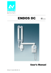
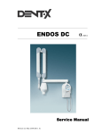
1
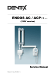
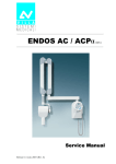
ENDOS AC / ACP
0051
User's Manual
Release 13 July 2007 (Rev. 6)
USER'S MANUAL
Revision history
Revision history
Rev.
Date
Page/s
0
07.02.03
-
1
11.04.03
All
Modification description
Document approval.
Introduction of KAILONG (China) X-ray tube.
Introduction of remote X-ray button with light
signaling of "Ready" or "Exposure in progress".
(Ref. RDM 5599)
2
25.09.03
All
3
26.03.04
8
Remote timer version release
Notify body change for CE mark.
(Ref. RDM 5781)
4
15.03.05
8, 20, 39
Editorial correction on Enabling/Disabling the
"Ready" key.
Modified the DP arm label.
(Ref. RDM 5938, RDM 6052)
5
10.01.06
30
Dose linearity reference measurement time updated.
(Ref. RDM 6164)
6
(Rev. 6)
13.07.07
All
Directive 2002/96/EC information notice added.
ENDOS AC/ACP - CE
USER'S MANUAL
Revision history
THIS PAGE IS INTENTIONALLY LEFT BLANK
ENDOS AC/ACP - CE
(Rev. 6)
USER'S MANUAL
Contents
Contents
1.
INTRODUCTION
1.1
2.
1
Icons in the manual................................................................................ 1
SAFETY ASPECTS
2
2.1
Warnings ................................................................................................ 3
2.2
Protection from X-rays............................................................................ 4
2.3
Environmental risks and disposal .......................................................... 5
2.4
Symbols in use ....................................................................................... 6
3.
CLEANING AND DISINFECTION
7
4.
DESCRIPTION
8
4.1
Identification labels ................................................................................ 8
4.2
Functions, Models and Versions........................................................... 10
4.2.1
4.2.2
4.2.3
4.3
Configurations...................................................................................... 12
4.3.1
4.3.2
4.3.3
4.3.4
4.3.5
4.3.6
5.
6.
Extension arm and scissors arm.......................................................... 10
Tubehead............................................................................................ 10
Timer.................................................................................................. 11
Standard configuration ....................................................................... 12
Remote timer configuration ................................................................. 13
Dental chair configuration................................................................... 14
Ceiling configuration ........................................................................... 15
Mobile stand configuration .................................................................. 16
Remote X-ray button configuration ...................................................... 17
TECHNICAL DATA
18
5.1
Method for correcting exposure times................................................... 21
5.2
Method for measuring technical factors................................................ 23
5.3
Correct use of dosimeters to measure exposure times .......................... 24
5.4
Curves tube features ............................................................................ 26
5.5
Reference standard............................................................................... 30
5.6
Overall dimensions ............................................................................... 32
GENERAL USE INSTRUCTIONS
34
6.1
"ENDOS ACP" timer.............................................................................. 34
6.2
"ENDOS AC" timer................................................................................ 38
6.3
Visual signals ....................................................................................... 40
(Rev. 6)
i
ENDOS AC/ACP - CE
USER'S MANUAL
Contents
7.
EQUIPMENT USE
7.1
Equipment preparation......................................................................... 42
7.1.1
7.1.2
7.1.3
Preparation of the tubehead ................................................................. 45
7.3
Exposure techniques ............................................................................ 49
Bisecting technique............................................................................. 49
Parallel technique ............................................................................... 51
7.4
Exposure .............................................................................................. 52
7.5
Special functions .................................................................................. 54
7.5.1
7.5.2
7.5.3
Counting the number of exposures made............................................. 54
Selection of multiplication factor for different types of film ................... 55
Selection of multiplication factor for Video-X-Ray-Digital ..................... 57
MESSAGES ON DISPLAY
58
8.1
Functional messages ............................................................................ 58
8.2
Error signalling..................................................................................... 61
8.2.1
8.2.2
8.2.3
9.
Preparation of the timer for X-ray use with automatic selection
of exposure times (only for ENDOS ACP version) .................................. 42
Preparation of the timer for radiographic use with manual selection
of exposure times................................................................................ 43
Preparation of the timer for Digital Radiography (Videoradiography)
use with automatic selection of exposure times (only ENDOS ACP
version) .............................................................................................. 44
7.2
7.3.1
7.3.2
8.
41
Non re-settable errors ......................................................................... 62
Non fatal errors in start-up phase ....................................................... 63
Errors in exposure phase .................................................................... 64
CHECK AND CORRECTION OF POSSIBLE ERRORS IN
DENTAL X-RAYS
65
9.1
Typical faults in intraoral X-rays .......................................................... 65
9.2
Typical faults caused by wrong positioning........................................... 67
10. MAINTENANCE
68
This publication can only be reproduced, transmitted, transcribed or translated
into any human or computer language with the written consent of the
Manufacturer.
This Manual is the English translation of the Italian original version.
ENDOS AC/ACP - CE
ii
(Rev. 6)
USER'S MANUAL
Introduction
1.
INTRODUCTION
*
NOTE:
This manual is updated to the product status it is sold with, to
guarantee the user an adequate reference for equipment use and any
aspect connected with use safety. The manual may not reflect any
product variation without impact on operating procedures and use
safety.
The intraoral radiographic ENDOS AC/ACP, produces high quality
intraoral X-rays, thanks to reduced exposure times and the small
dimensions of the focal spot.
ENDOS AC/ACP is exclusively intended for the execution of
intraoral X-rays.
The equipment has the following features:
• Very good quality X-rays pictures
• user friendly
• ergonomic design.
The equipment is controlled by a microprocessor that makes it possible
to reproduce exposure times and is composed of the following parts:
• Timer: ENDOS AC or ENDOS ACP equipped with wall plate
• Extension arm (30 cm, 60 cm or 80 cm for wall version)
• Scissors arm (DP)
• Tubehead 70 kV 8 mA – X-ray tube with grid.
The purpose of this manual is to provide the user with instructions that
will allow him to run the equipment safely and efficiently.
The equipment must be used according to the procedures in the manual
and never for different purposes from the ones for which it has been
designed.
1.1
Icons in the manual
*
Indicates a “NOTE”; we recommend particular attention in reading the
subjects identified with this icon.
Indicates a “WARNING”; subjects identified with this icon concern
safety aspects regarding the patient and/or the operator.
(Rev. 6)
1
ENDOS AC/ACP - CE
USER'S MANUAL
Safety aspects
2.
SAFETY ASPECTS
WARNING:
Read this chapter very carefully.
Villa Sistemi Medicali designs and makes their equipment according to
safety requirements; moreover, they supply all necessary information for
appropriate use and warnings relating to dangers connected with X-ray
generators.
The manufacturer does not accept any responsibility for:
•
Use of ENDOS AC/ACP equipment for purposes other than those for
which it has been designed,
•
damages to the equipment, the operator, the patient caused both by
wrong installations and maintenance that do not follow the
procedures contained in the user manuals and the installation
provided with the equipment, and by wrong operating techniques,
•
mechanical and / or electrical changes , made during and after
installation, that differ from the ones in the Service Manual.
Only personnel authorised by the Manufacturer may carry out
technical work on the equipment.
Only authorised personnel can remove the tubehead from its
support and/or gain access to live parts.
ENDOS AC/ACP - CE
2
(Rev. 6)
USER'S MANUAL
Safety aspects
2.1
Warnings
The equipment must be used according to the procedures in this manual
and never for different purposes from the ones for which it has been
designed.
Before carrying out any maintenance disconnect the equipment from the
power line using the circuit breaker provided.
ENDOS AC/ACP is an electro-medical device and for this reason can be
used only under the supervision of highly qualified medical staff in
possession of all the necessary knowledge about X-ray protection.
The user is responsible for fulfilling all the legal requirements connected
with the possession, installation and use of the equipment itself.
ENDOS AC/ACP is built for continuous running with intermittent load;
for this reason the planned duty cycle must be observed.
Appropriate accessories, such as lead aprons, must be used to protect
the patient from radiation.
Although the equipment is designed to provide a reasonable degree of
protection from electromagnetic interference, according to IEC
International regulations, it must be installed at an adequate distance
from electricity transformer rooms, static continuity units, from two-way
amateur radios and cellular phones. The latter can be used only at a
minimum distance of 1.5m from any part of the equipment.
Any instrumentation or equipment for professional use located near
ENDOS AC/ACP must conform to Electromagnetic Compatibility
regulations. Non conforming equipment, with known poor immunity to
electromagnetic fields, must be installed at a distance of at least 3m from
ENDOS AC/ACP and supplied by a dedicated electric line.
ENDOS AC/ACP must be turned off when using electro-cautery or
similar equipment in the vicinity of the equipment itself.
The equipment is not designed to be used in the presence of anaesthetic
mixtures inflammable with air, oxygen or nitrous oxide.
Equipment parts which may come into contact with the patient must be
cleaned regularly according to the instructions given later in this
document.
WARNING:
For safety reasons, it is forbidden to overload the extension arm or the
scissors arm in an anomalous way, for instance by leaning on it.
(Rev. 6)
3
ENDOS AC/ACP - CE
USER'S MANUAL
Safety aspects
2.2
Protection from XX-rays
Although dosage given by modern X-ray equipment is low on average,
during the execution of the exposure, the operator must take all
precautions to protect the patient and himself in compliance with the
regulations in force.
WARNING:
Protection from X-ray radiation is regulated by law. The equipment must
be used by specialised personnel only.
a)
The film (or the digital sensor) must be put into the patient’s mouth
manually or using the appropriate supports. If possible it must be
held by the patient himself.
b)
During X-ray exposure, the operator must not come into contact
with the tubehead or the collimator cone.
c)
During exposure, the operator must be at a certain distance from the
X-ray source (at least 2 metres), in the opposite direction to X-ray
beam.
d) During exposure, the operator and the patient are the only people
allowed in the room.
e)
The lead aprons should be used to reduce the undesirable effect of
secondary radiation on the patient.
ENDOS AC/ACP - CE
4
(Rev. 6)
USER'S MANUAL
Safety aspects
2.3
Environmental risks and disposal
Some parts of the equipment contain material and fluids which must be
disposed of in special areas designated by the local health authorities at
the end of the equipment’s life cycle.
In particular the equipment contains the following materials and / or
components:
*
•
Tubehead: hard plastic materials, metal materials, glass, dielectric
oil, lead, tungsten
•
Other parts of the equipment: hard plastic materials, metal
materials, printed circuits, iron-plastic materials.
NOTICE FOR THE USERS IN THE E.C.
According to the Directive 2002/96/EC on Waste from Electrical
and Electronic Equipment.
The crossed out wheeled bin symbol placed on the equipment or its
package means that the equipment must be collected separately from
the other waste.
The separate collection of this equipment at the end of its life cycle is
managed by the manufacturer/distributor. The user that want to discard
this equipment should contact the local distributor and follow the
system he adopted for the separate collection.
The correct separate collection for the subsequent recycling, treatment
and environmentally compatible disposal contributes to avoid negative
effects on the environment and on the health and promotes the reuse
and/or recycling of the materials that the equipment is made of.
The illegal disposal of the equipment made by the user will cause the
application of sanctions according to the local regulations.
(Rev. 6)
5
ENDOS AC/ACP - CE
USER'S MANUAL
Safety aspects
2.4
Symbols in use
The following symbols are used in this manual and in ENDOS AC/ACP,
besides the symbols on the keyboard (see chapter 6):
Symbol
Description
Equipment with applied parts Type B
A number of machine parts contain materials and
liquids that upon completion of the machine’s life
cycle must be disposed of at recovery centers
established by the local health units
∼
Alternate current
N
Connecting point to neutral conductor
L
Connecting point to live conductor
Protection ground
Functional ground
OFF ; equipment not connected to electricity line
ON ; equipment connected to electricity line
Permission key to exposure; the permitted exposure
status is displayed by switching on the corresponding
green symbol
Focal spot according to IEC 336
X-ray emission
ENDOS AC/ACP - CE
6
(Rev. 6)
USER'S MANUAL
Cleaning and disinfection
3.
CLEANING AND DISINFECTION
DISINFECTION
The following procedures should be observed carefully in order to
guarantee accurate hygiene and cleaning:
•
Before cleaning the equipment disconnect it from the line using
the cut-out switch which must be provided when setting up. This
operation is necessary as some internal parts remain live even
after it has been switched off from the on board switch.
•
Be careful not to let water or other fluids enter the equipment in
order not to cause a short circuit and corrosions.
•
Never use solvents (alcohol, petrol, Trichloroethylene), corrosive or
abrasive substances when cleaning.
External surfaces
Use a soft cloth and, for a stronger action, a neutral soap to prevent
damaging painted surfaces.
During cleaning operations, prevent surplus detergent and/or fluids
entering the equipment or staying on painted surfaces.
Parts that come into contact with the patient’s
patient’s skin
These parts should be disinfected at regular intervals with a 2%
Glutaraldeide solution to guarantee hygiene.
(Rev. 6)
7
ENDOS AC/ACP - CE
USER'S MANUAL
Description
4.
DESCRIPTION
4.1
Identification labels
3
4
2
1
ENDOS AC/ACP - CE
8
(Rev. 6)
USER'S MANUAL
Description
1
ENDOS AC/ACP
label
2a
2b
Tubehead label
(X-ray tube type CEI)
3
DP arm
label
(Rev. 6)
Tubehead label
(X-ray tube type KAILONG)
4
5
Extension arm
label
Collimator 30 cm (optional)
label
9
ENDOS AC/ACP - CE
USER'S MANUAL
Description
4.2
Functions, Models and Versions
ENDOS AC/ACP intraoral radiographic equipment is composed of the
following parts:
4.2.1
Extension arm and
and scissors arm
It is composed of a double articulated joint arm, enabling extension
horizontally and vertically. The tubehead is balanced in all positions.
*
NOTE:
The scissors arm is designed to work correctly at a max. angle of 160°; so
its use requires a flare angle of less than 160°.
Moreover, a horizontal extension arm can be added, available in various
sizes, to meet all requirements.
4.2.2
Tubehead
The 70 kVp voltage, the 8 mA current and the use of a tube with
grid reduce exposure times and the quantities of X-rays absorbed
by the patient. The radiogenic equipment is provided with a
collimator with 20 cm focus skin distance and a 6 cm X-ray
emission diameter at the exit of the cone. The tubehead is
connected to the arm by a guide, which allows 360° horizontal
rotation and 290° vertical rotation.
Two alternate X-ray tube can be used: both have the same
characteristics and provide the same performance.
The tubehead, assembled with different X-ray tubes, are interchangeable
so long as preheating time is set to the proper value indicated on the
tubehead label.
ENDOS AC/ACP - CE
10
(Rev. 6)
USER'S MANUAL
Description
4.2.3
Timer
The name of ENDOS AC/ACP depends on the type of timer in use:
•
ENDOS ACP
ENDOS ACP is a digital timer with microprocessor where
exposure times can be selected both manually and
automatically.
With automatic selection there is a choice of 30 pre-set times
depending on the patient’s size (small, medium or large) and
the type of tooth and acquisition mode (film, digital).
There are 33 fixed manual selection times that vary from a
minimum of 0.02 seconds to a maximum of 3.20 seconds.
The main feature of this timer is that it has an automatic
exposure time compensation for drift of nominal voltage within
± 10%.
•
ENDOS AC
ENDOS AC has the same features as the ENDOS ACP timer,
excluding automatic and digital anatomic selection.
It has manual exposure time selection only.
*
NOTE:
A remote X-ray button configuration can be made, outside the exam
room. This can be a pure doorbell X-ray button or a device which also
show status of the unit ("READY" and "EXPOSURE IN PROGRESS".
*
NOTE:
The equipment supplies two separate contacts for connection with
external signalling devices. One contact shows the status of functioning
equipment ready for use and the second one the X-ray emission.
Connection procedures and the necessary requisites for signalling
devices are given in the "Service Manual".
(Rev. 6)
11
ENDOS AC/ACP - CE
USER'S MANUAL
Description
4.3
Configurations
4.3.1
Standard configuration
2
4
1
3
5
Figure 1
ENDOS AC/ACP - CE
1
Tubehead
2
Scissors arm
3
Extension arm
4
Timer
5
X-ray button
12
(Rev. 6)
USER'S MANUAL
Description
4.3.2
Remote timer configuration
2
1
4
5
3
6
Figure 2
(Rev. 6)
1
Tubehead
2
Scissors arm
3
Extension arm
4
Wall support (kit code 8161301002)
5
Remote timer
6
X-ray button
13
ENDOS AC/ACP - CE
USER'S MANUAL
Description
4.3.3
Dental chair configuration
2
5
3
6
1
4
Figure 3
ENDOS AC/ACP - CE
1
Tubehead
2
Scissors arm
3
Dental chair extension arm 30 cm
4
Dental chair connection
5
Timer
6
X-ray button
14
(Rev. 6)
USER'S MANUAL
Description
4.3.4
Ceiling configuration
2
4
3
1
5
6
Figure 4
(Rev. 6)
1
Tubehead
2
Scissors arm
3
Ceiling extension arm
4
Ceiling suspension plate
5
Timer
6
X-ray button
15
ENDOS AC/ACP - CE
USER'S MANUAL
Description
4.3.5
Mobile stand configuration
2
5
3
1
4
Figure 5
ENDOS AC/ACP - CE
1
Tubehead
2
Scissors arm
3
Mobile stand
4
Timer
5
X-ray button
16
(Rev. 6)
USER'S MANUAL
Description
4.3.6
Remote XX-ray button configuration
2
1
Figure 6
Alternative 1:
1
X-ray button (not supplied)
Alternative 2:
2
(Rev. 6)
X-ray button + light signalling of "Ready"
or "Exposure in progress" (supplied as kit
P/N 6661309500)
17
ENDOS AC/ACP - CE
USER'S MANUAL
Technical data
5.
TECHNICAL DATA
Technical features
Equipment
ENDOS AC/ACP
Manufacturer
VILLA SISTEMI MEDICALI
Buccinasco (MI)
Class
Class I° with type B applied parts
(EN 60601-1 classification)
Protection level
Standard Apparatus IP20
Line voltage
230 V∼ ± 10%
Line frequency
50 Hz
Absorbed current
4 A rms impulsive @ 230 V ∼
Power consumption
920 VA impulsive @ 230 V ∼
Max. apparent line resistance
0.8 Ω max.
Main fuse
6 AF
Pre-set exposure times
from 0.02 to 3.2 s in 33 steps
Automatic selection
(only for ENDOS ACP)
30 pre-set times
Exposure time accuracy
± 10% or ± 20 ms
(whichever is greater - see note
paragraph 5.5)
Circuit type
Single phase self-rectifying with grid
control
kV selection (high voltage value)
70 kVp
Tubehead current
8 mA
KV accuracy
± 6 % @ nominal voltage
Tubehead (anode) current accuracy
± 13 % @ nominal voltage
Max. exposure time
3.2 s
Timer dimension
345×195×100 mm
ENDOS AC/ACP - CE
18
(Rev. 6)
USER'S MANUAL
Technical data
Tubehead features
Manufacturer
VILLA SISTEMI MEDICALI
Buccinasco (MI)
Rated voltage
70 kVp
Tubehead power
430 W
Pre-heating time
100 ms
Total filtration
≥ 2 mm Al eq. @ 70 kV
HVL (Half Value Layer)
> 1.5 mm Al eq.
Transformer insulation
Oil bath
Interval between exposures /
duty cycle
32 times X–ray time /
1 : 32
Focal spot
0.8 (IEC 336)
Minimum focus to skin distance
20 cm (optional 30 cm cone)
X-ray beam diameter (@ 20cm focus)
≤ 6 cm (optional 35x43 mm)
Cooling
Convection
Radiation leakage at 1 m
< 0.1 mGy/h
Technical factors for radiation leakage
70 kV, 8 mA, 1 s duty cycle
1 exposure each 32 seconds
X-ray tube features
Manufacturer
CEI Bologna
(Italy)
KAILONG Electronic
(China)
Type
OCX/ 70-G
with grid
KL16 - 0.8 - 70G
Inherent filtration
0.5 mm Al
equivalent to 70 kV
0.4 mm Al
equivalent to 70 kV
Anode tilt
19°
19°
Anode material
Tungsten
Tungsten
Rated voltage
70 kV
70 kV
Maximum filament current
2.8 A
2.8 A
Maximum filament voltage
4V
4.1 V
Anode thermal capacity
6 kJ
7 kJ
(Rev. 6)
19
ENDOS AC/ACP - CE
USER'S MANUAL
Technical data
Environmental conditions
Operating temperature range
+10°C ÷ +40°C
Operating relative humidity range
30% ÷ 75%
Temperature range for transport and
storage
-20°C ÷ +70°C
Max. relative humidity for transport and <95 % non condensing
storage
Min. atmospheric pressure for storage
and transport
630hPa
Apparatus and detachable parts weight
Gross weight including packing
30.4 kg
Net apparatus weight in standard
configuration
25.4 kg
60 cm extension arm (standard)
2.9 kg
80 cm extension arm
3.5 kg
30 cm extension arm
1.9 kg
Scissors arm
9 kg
Timer plus wall plate
5 kg
Tubehead
8.5 kg
ENDOS AC/ACP - CE
20
(Rev. 6)
USER'S MANUAL
Technical data
5.1
Method for correcting exposure times
This RX intraoral equipment features a special function called Computer
Controlled Density which makes it possible to correct exposure time
automatically when line voltage is different from its nominal voltage.
A change in the line voltage affects the peak voltage applied to the RX
tube and the high voltage value affects the Rx spectrum very
significantly. This, in turn, affects the optical density of the image on the
film. The task of the correction is to achieve the same optical image
density irrespective of the variations in line voltage, within its permitted
variation range of ± 10%. In short, this feature makes it possible to
obtain the same quality of image without having to be concerned about
possible line variations which occur frequently in many areas and which
are almost impossible to prevent without resorting to costly equipment.
Automatic exposure time correction works with the following sequence:
inside the timer there is a voltmeter which takes a constant reading of
the line voltage, while the user selects the desired exposure time. After
the user has chosen the exposure time he knows from experience to be
the best for the type of X-ray he is going to take, the user himself presses
the key enabling exposure and the timer shows on the screen the correct
time that will be used for the exposure in progress, time that the timer
itself has calculated according to the value of the line voltage measured
an instant before pressing the key of the exposure permission.
*
NOTE:
ENDOS AC and ENDOS ACP timers work in step with the line frequency,
so the calculated time is always rounded off to the multiple of the line
frequency itself.
The correct exposure time shown once the timer has been enabled by the
"Ready" key and during the execution of the X-ray is the time actually
used by the equipment: it is calculated applying a correction factor to the
time selected by the user, based on the empirical law relating to the
optical density of the film with the high voltage peak value and
consequently with the line voltage.
*
(Rev. 6)
NOTE:
If the "Ready" key has been disabled in system configuration, the display
will show the "corrected" exposure time only during exposure or holding
the X-ray button pressed at the end of it.
21
ENDOS AC/ACP - CE
USER'S MANUAL
Technical data
The qualitative relation between the multiplication factor and the line
voltage is shown in the following picture (for equipment configured to
work at 230V):
Multiplication factor
of exposure time to
the variation of line
voltage
1,75
1,5
1,25
1
0,75
0,5
206
218
230
242
254
Line voltage
ENDOS AC/ACP - CE
22
(Rev. 6)
USER'S MANUAL
Technical data
5.2
Method for measuring technical factors
kVp
KVp value is defined as the stationary value of high voltage applied to
the tube which settles on load after preheating time.
KVp value is measured by a non-invasive instrument, with accuracy of
over 2%, to the nominal value of line voltage.
A direct high voltage measurement can be made only by disassembling
the tubehead. This operation can be executed only in the factory.
mA
The anodic current value is defined as the average value of stationary
current which settles on load after pre-switching time.
The anodic current value is measured using a digital voltmeter
measuring the voltage drop at the ends of the resistance from 1 kΩ, 1%
assembled on the tubehead. To take this measurement, remove the side
plastic plug of the tube support; connect the ground voltmeter terminal
on the yellow/green cable clamp screw and insert the positive terminal
into the contact at the end of the grey cable. The digital voltmeter must
be selected on DC, and the relation of transformation is given by 1 mA =
1V. Execute an exposure of at least 1 sec.
t
The exposure time value is the time during which the value of the anodic
peak current exceeds 25% of the steady state value. The time taken to
reach this condition is called "pre-heating time".
The measurement must be taken at nominal line voltage, measuring the
anodic current wave-form on the 1kΩ resistance and using a memory
oscilloscope.
Exposure time measurements using non-invasive equipment can
lead to systematic errors in exposure time measurements which
cannot be quantified and which depend on the equipment used for
measuring (see paragraph 5.3).
(Rev. 6)
23
ENDOS AC/ACP - CE
USER'S MANUAL
Technical data
5.3
Correct use of dosimeters to measure exposure
times
The spread of non-invasive equipment to measure the functional
parameters of RX equipment has introduced a series of interpretation
problems when measuring exposure times.
The source of the problem is in the characteristic rise curve of the RX
tube’s anodic current which is represented in the picture:
Anodic
current
Time
According to IEC60601-2-7 (1998) regulations, "in equipment where the
filament is switched on and high voltage is applied simultaneously, the
exposure time is calculated as the interval between the instant when the
anodic current exceeds 25% of the nominal value and the instant when
it goes below such value".
This method is defined as invasive because it requires that the anodic
current flowing through a resistance inside the tubehead must be
measured.
Non-invasive methods are definitely easier and faster compared with the
invasive method, but they are prone to errors which can be considerable
when determining exposure time. In fact some of these devices start
counting exposure time as soon as a small quantity of radiation reaches
the measuring chamber with the result that they take longer times than
the ones determined by the invasive method applied by the
manufacturer.
Consequently, calculations obtained by these non-invasive methods can
erroneously lead to the conclusion that the equipment timer is not
accurate. Actually the difference is connected to the method adopted in
measuring the exposure time.
ENDOS AC/ACP - CE
24
(Rev. 6)
USER'S MANUAL
Technical data
By using a tube with grid it is possible to reduce to the minimum the
time required for the anodic current, and as a consequence, the dose
adjustment to reach the steady state, so there is very little difference
between the exposure time measurement using the invasive and the non
invasive method.
Corrective actions
A practical method can be applied to get round the problem which can
be described this way:
• In a graph you report the values of times measured using the
equipment compared with the ones displayed by the timer
(automatically corrected for the line variations): the dots of the graph
are interpolated with a straight line (if possible by the least square
method or more simply in a graphic way).
• You determine the intercept on the Y axis of this straight line: this
can be assumed as the time value that the non-invasive device adds
to each measurement due to the radiation which reaches the device
before the anodic current is 25% of its maximum value.
• Then you subtract this "offset" time from all the device measurements
and you proceed with comparing the time measurements displayed
by the timer.
(Rev. 6)
25
ENDOS AC/ACP - CE
USER'S MANUAL
Technical data
5.4
Curves tube features
OCX / 70-G
Feature of emission
Load
ENDOS AC/ACP - CE
26
(Rev. 6)
USER'S MANUAL
Technical data
Curve anode cooling
Curve tubehead cooling
(Rev. 6)
27
ENDOS AC/ACP - CE
USER'S MANUAL
Technical data
KL16 – 0.8 – 70G
Feature of emission
Filament characteristics
ENDOS AC/ACP - CE
28
(Rev. 6)
USER'S MANUAL
Technical data
Heat storage (kJ)
Curve tubehead cooling
(Rev. 6)
29
ENDOS AC/ACP - CE
USER'S MANUAL
Technical data
5.5
Reference standard
Enforceable regulations:
CEE 93/42:
*
EN
EN
EN
EN
EN
EN
EN
60601-1
60601-1-1
60601-1-2
60601-1-3
60601-1-4
60601-2-7 (see NOTE)
60601-2-28
NOTE:
The technology employed in AC intraoral equipment, where the line
voltage is applied simultaneously to the high voltage transformer and to
the filament of the Rx tube, causes the two following deviations
according to EN 60601-2-7 (ed.1998) requirements:
a) The exposure time cannot be defined with an accuracy lower than
the length of a 50Hz line period (20ms) and than two 60Hz line
periods (16.6ms).
In fact exposure time is defined as the interval between the instant
when the anodic current exceeds 25% of the steady state value and
the instant when it goes below this value. It is evident that in the
anodic current rise current (see Figure paragraph 5.3) you have the
uncertainty of 1 peak in determining the first peak which exceeds
25% of the steady state anodic current.
When running at 60Hz you must also consider that selectable times
in the timer are not always multiples of the line period. This
introduces a further approximation that the timer executes
automatically to carry the selected time to the nearest multiple of the
line period.
b) EN 60601-2-7 (ed. 1998) regulation defines precisely that for each
pair of exposure times (in ENDOS AC/ACP equipment is the only
selectable parameter), with a near relation, but lower than 2, dose
linearity is calculated by the formula:
Dose(t1) / t1 − Dose(t 2) / t 2 ≤ 0.2 × (Dose(t1) / t1 + Dose(t 2) / t 2)
2
Again, due to the characteristic the anodic current rise curve in AC
equipment, the linearity limit is not respected for very short
exposure times.
In fact it is evident that for any exposure time a "basal dose" is
emitted, produced in the period between the application of voltage to
the tubehead and the time when anodic current exceeds 25% of
steady state, assumed as the exposure time start.
ENDOS AC/ACP - CE
30
(Rev. 6)
USER'S MANUAL
Technical data
Moreover, the interval between exceeding 25% of the steady state
anodic current and reaching running point, the anodic current grows
and with it the dose rate, making the emitted dose non-proportional
to the exposure time.
The use of a tube with grid substantially limits the "basal" dose and
also the dose emitted at the start of the exposure time , before the
anodic current reaches the stationary status.
In ENDOS AC/ACP equipment, typically the basal dose and the dose
emitted in the interval when the anodic current varies between 25%
of the running value and stationery point is very low, thanks to the
tube with grid and this makes it possible to guarantee that the
linearity requirements contained in EN 60601-2-7 (ed.1998) are
respected for exposure times starting from 60ms.
(Rev. 6)
31
ENDOS AC/ACP - CE
USER'S MANUAL
Technical data
5.6
Overall dimensions
Figure 7: Overall dimensions wall version
70░
Figure 8: Overall dimensions ceiling version
ENDOS AC/ACP - CE
32
(Rev. 6)
USER'S MANUAL
Technical data
60░
360░
70░
Figure 9: Overall dimensions Mobile Stand version
(Rev. 6)
33
ENDOS AC/ACP - CE
USER'S MANUAL
General use instructions
6.
GENERAL USE INSTRUCT
INSTRUCTIONS
IONS
6.1
"ENDOS ACP" timer
1
2
18
17
9
16
10
11
12
5
13
6
3
15
7
14
4
8
Figure 10: Control keyboard ENDOS ACP
1
"X-ray emission" yellow LED
10 "Upper molar" LED
2
"Ready for X-ray" green LED
11 "Lower molar" LED
3
Exposure enabling "READY"
12 "Premolars" LED
4
"Size" selection key
13 "Incisors / Canines" LED
5
"Large size" LED
14 Videography selection key
6
"Medium size" LED
15 "Videography" LED
7
"Small size" LED
16 Increase key
8
"Tooth anatomic" selection key
17 Decrease key
9
"Bite-wing" LED
18 Three figure display
ENDOS AC/ACP - CE
34
(Rev. 6)
USER'S MANUAL
General use instructions
*
NOTE:
All automatic selections are indicated by switching on the relative
luminous signalling, at the bottom on the left of the symbol.
*
NOTE:
ENDOS ACP timer is provided with a Stand By function, so, if no key is
pressed for 5 minutes, the timer goes into stand-by (low consumption),
indicated on the display by the presence of only the decimal point on the
right. To go back to the operative condition, press any key.
INCREASE KEY exposure time
DECREASE KEY exposure time
By pressing any of these keys, you go from automatic selection to
manual selection. In this way, all signals related to automatic selection
(Patient’s size, Tooth Selection, Digital Sensor) are switched off. So time
selection will work in a manual way.
You can select quickly by keeping the key pressed; in this way the
variation works quickly.
To go back to the automatic time selection, press one of the Selection
keys (Patient’s Size, Tooth, Digital Sensor).
“SIZE” selection key
Press key (4)
medium
to select from different patient sizes:
and large
small
.
Even in this case exposure times vary.
An acoustic signal (about ½ second) is linked to each touch of the key
linked to switching on the selected function from the LED.
(Rev. 6)
35
ENDOS AC/ACP - CE
USER'S MANUAL
General use instructions
“TOOTH ANATOMIC” selection
selection key
Press key (8)
to select from the exposure times provided for the
different teeth. The meaning of symbols is explained as follows.
Bite-wing
Upper molar
Lower molar
Premolars
superior or
inferior
Incisors /
Canines
superior or
inferior
Exposure enable key (Ready)
For additional safety, ENDOS ACP timer is provided with an "Enabling of
exposure" function.
X-rays can be emitted only after pressing the key
. The
equipment enabled signal is displayed on the keyboard by switching on
the corresponding green signal. This enabled signal stays for a set time
(variable during setup between 10 and 30 seconds: default 15 seconds),
after which the function itself is disabled and X-rays are not emitted if
the exposure button is touched.
*
NOTE:
When the READY key is pressed not only will exposure be enabled, but
the equipment will also start displaying exposure time on the display
calculated according to line voltage fluctuation compensation (see
paragraph 5.1).
ENDOS AC/ACP - CE
36
(Rev. 6)
USER'S MANUAL
General use instructions
Digital selection key
Key (14)
enables automatic exposure for Digital X-rays, reducing
exposure times to values suitable to digital sensors.
*
NOTE:
Value setting and the setting of the exposure time reduction factor in
digital selection by the operator are described in paragraph 7.5.3.
*
NOTE:
This key and the connected functions, can be disabled by the Technical
Service in the set-up phase.
(Rev. 6)
37
ENDOS AC/ACP - CE
USER'S MANUAL
General use instructions
6.2
"ENDOS AC" timer
1
2
6
5
4
1. "X-ray emission"
yellow LED
2. "Ready for X-rays"
green LED
3. Exposure permission
"READY"
4. Increase key
5. Decrease key
6. Three figure display
3
Figure 11: Control keyboard ENDOS AC
*
NOTE:
ENDOS AC timer is provided with Stand By function, so if a key is not
pressed for 5 minutes the timer goes into stand-by (low consumption),
shown on display by the presence of the decimal point on the right only.
Press any key to go back to the operative condition.
INCREASE KEY exposure time
DECREASE KEY exposure time
By pressing one of these keys, you can select exposure time by turning
the key onto one of the 33 available times.
Press the increase and decrease keys to modify the pre-set time; you can
select quickly by keeping the key pressed; in this way the variation
happens quickly.
ENDOS AC/ACP - CE
38
(Rev. 6)
USER'S MANUAL
General use instructions
Equipment enabling key
For additional safety, ENDOS AC timer is provided with the "Exposure
enabling" function.
X-rays can be emitted only after pressing the key
.
The equipment enabled signal is displayed on the keyboard by switching
on the corresponding green signal. This enabling lasts for a pre-set time
(variable during setup phase between 10 and 30 seconds: default 15
seconds), after which the function itself is disabled and no X-rays are
emitted if the exposure button is touched.
*
(Rev. 6)
NOTE:
When the READY key is pressed not only will exposure be enabled, but
the equipment will also start displaying exposure time on the display
calculated according to line voltage fluctuation compensation (see
paragraph 5.1).
39
ENDOS AC/ACP - CE
USER'S MANUAL
General use instructions
6.3
Visual signals
Equipment enabling signalling
When on, the green signal
, at the top left-hand corner of the
keyboard, shows "Ready for X-rays" condition, where a touch of the
X-ray button starts exposure. This exposure enabled condition stays
until the exposure ends or for a pre-set time (variable during set-up
between 10 and 30 seconds: default 15 seconds), after which the
condition itself is disabled; in this case you must reactivate by touching
the corresponding key again.
*
NOTE:
When the READY key is pressed not only will exposure be enabled, but
the equipment will also start displaying exposure time on the display
calculated according to line voltage fluctuation compensation (see
paragraph 5.1).
*
NOTE:
If the READY key has been disabled in system configuration, the display
will show the "corrected" exposure time only during exposure or holding
the X-ray button pressed at the end of it.
*
NOTE:
If you touch the X-ray button when the enabling signal is not active, no
exposure occurs; at the same time the display shows the latest actual
exposure time.
Signal "X"X-RAY EMISSION"
The yellow luminous signal
, at the top right-hand corner of the
keyboard is activated if X-rays are being emitted, signalling that
emission is actually taking place. Emission is also signalled by an
acoustic signal.
Display showing exposure times
The display, in the middle top part of the keyboard has a multiple
function.
1. During the exposure preparation phase, it displays the automatically
or manually selected exposure time.
2. Soon after enabling the equipment by pressing the "Ready" key and
during the exposure phase, it displays exposure time corrected by
the equipment to compensate line voltage fluctuations, while at the
end of the exposure it displays the time that must elapse before the
end of the tubehead cooling pause.
3. At the end, if you press the X-ray button with exposure not enabled,
the display shows the latest actual exposure time.
ENDOS AC/ACP - CE
40
(Rev. 6)
USER'S MANUAL
Equipment use
7.
EQUIPMENT USE
a)
Press the switch-on button located at the bottom of the timer.
This operation will start the equipment’s automatic control function.
b)
After completing the control function (possible anomalies pointed out
are signalled by error messages described in chapter 8), the
equipment displays the standard anatomic selection or the selection
pre-set before switching off, according to the mode chosen during
setting up.
NOW THE EQUIPMENT IS READY FOR USE.
(Rev. 6)
41
ENDOS AC/ACP - CE
USER'S MANUAL
Equipment use
7.1
Equipment preparation
7.1.1
Preparation of the timer for XX-ray use with automatic
selection of exposure times (only for ENDOS ACP version)
If you want to enable the automatic selection you must choose
the patient’s size using keys:
-
-
. You will then set
the type of tooth to be examined choosing from the projections:
By pressing the keys on the control panel the selection made is
highlighted by an acoustic signal and the LED relating to the pressed
key turns on . The selected size/tooth combination, will produce the
basic exposure time on the display (see Table 1). Exposure times shown
are those suggested for Ultra Speed Kodak films (Type D).
0.25
0.32
0.50
0.36
0.63
0.80
0.32
0.50
0.70
0.32
0.50
0.70
0.25
0.32
0.50
Table 1
ENDOS AC/ACP - CE
42
(Rev. 6)
USER'S MANUAL
Equipment use
*
7.1.2
NOTE:
When using different types of film (example type E), the multiplication
factor must be modified for automatic selection. This modification can be
made by the Service Technician during setting up or made directly by
the user (see paragraph 7.5.2).
It is necessary to set the multiplication factor shown on the
documentation provided by the film producer.
Preparation of the timer for radiographic use with manual
selection of exposure times
Enable manual selection working on keys
and
.
By enabling manual selection, the automatically pre-set time will
increase by pressing key
and decrease by pressing key
To increase or decrease times click by click press one of the keys several
times; you will hear an acoustic signal as the times vary. Holding one of
the keys pressed, times increase or decrease quickly according to the
respective scale bottom. Manually selectable times are 33 and go from
0.02 minimum to 3.20 seconds maximum (see Table 2).
0.02 - 0.04 - 0.06 - 0.08 - 0.10 - 0.12 - 0.14 - 0.16 - 0.18 - 0.20 - 0.23
- 0.25 - 0.30 - 0.32 - 0.36 - 0.40 - 0.45 - 0.50- 0.54 - 0.60 - 0.63 -0.70
- 0.80 - 0.90 - 1.00- 1.25 -1.30 - 1.40 - 1.60 - 2.00 - 2.50 - 3.00 - 3.20
Table 2
*
(Rev. 6)
NOTE:
See paragraphs 5.1, 5.2, 5.3.
43
ENDOS AC/ACP - CE
USER'S MANUAL
Equipment use
7.1.3
*
Preparation of the timer for Digital Radiography
(Videoradiography) use with automatic selection of
exposure times (only ENDOS ACP version)
NOTE:
This automatic program is used only if you have intraoral Video-Digital
Radiography equipment.
Press key (14)
; the related signal switches on and times
displayed on the display will be reduced in comparison with the use of
the equipment with films and anyway they will reflect the selection made
(Size, Tooth).
*
a)
Digital X-ray exposure is selected automatically by selecting one of
the available times.
b)
To return to radiographic automatic selection press key
again.
NOTE:
The digital exposure time reduction factor can be modified by the Service
Technician during setting up or directly by the user (see paragraph
7.5.3).
ENDOS AC/ACP - CE
44
(Rev. 6)
USER'S MANUAL
Equipment use
7.2
Preparation of the tubehead
a)
Set the tubehead with an angle suitable for the exposure and
positioning requested (see Figure 12, Figure 13, Figure 14,
Figure 15).
b)
Put the film into the patient’s mouth according to the chosen way
(bisecting or parallel). For this purpose, see paragraph 7.3.
c)
Move the tubehead cone towards the patient and focus it exactly
towards the tooth to X-ray referring to the following Figures.
*
NOTE:
If you want to use the rectangular collimator 35x43, assemble it by
clicking it on the end of the collimator cone, position it as requested.
*
NOTE:
If you want to use the extended 30 cm cone, snap it on the 20 cm cone.
WARNING:
Anatomical preset times are no more valid when 30cm cone is mounted.
Typically times necessary to obtain the same optical density must be
multiplied by a factor 2.25, operating in manual exposure time selection.
(Rev. 6)
45
ENDOS AC/ACP - CE
USER'S MANUAL
Equipment use
LOWER JAW (MANDIBLE)
-15°
-15°
INCISIVI
incisors
incisives
CANINI
canines
canines
-5°
-10°
PREMOLARI
premolars
prémolaires
MOLARI
molars
molaires
Figure 12
ENDOS AC/ACP - CE
46
(Rev. 6)
USER'S MANUAL
Equipment use
UPPER JAW
+40°
+40°
INCISIVI
incisors
incisives
CANINI
canines
canines
+30°
+20°
PREMOLARI
premolars
prémolaires
MOLARI
molars
molaires
Figure 13
(Rev. 6)
47
ENDOS AC/ACP - CE
USER'S MANUAL
Equipment use
OCCLUSAL
+65°
0°
MASCELLA
upper jaw
machoire
MANDIBOLA
lower jaw
mandibule
Figure 14
BITE WING
film
rc
rc =
RAGGIO CENTRALE
main beam
rayon central
0°
Figure 15
ENDOS AC/ACP - CE
48
(Rev. 6)
USER'S MANUAL
Equipment use
7.3
Exposure techniques
This paragraph describes the different techniques generally used for
intraoral exposure.
7.3.1
Bisecting technique
Incidence X-ray beam – Vertical angle
To get a real image of the tooth, the X-ray must be perpendicular to the
bisecting line of the angle formed by the longitudinal axis of the tooth
and by the film.
After positioning the X-ray beam and the patient’s head according to
these criteria, it is possible to apply an average vertical incidence for
each area. The incidence angle of the X-ray beam can be correctly
measured by the graded scale applied to the tubehead.
Figure 16
Legend Figure 16:
A – Tooth longitudinal axis
B – Bisecting line
C – Film level
D - Occlusal level
RC - X-ray beam
(Rev. 6)
49
ENDOS AC/ACP - CE
USER'S MANUAL
Equipment use
X-ray beam incidence – Horizontal direction
The X-ray beam must be set horizontally, in particular in the orthoradial direction regarding inter-proximal spaces (see Figure 17), in order
to avoid a superimposition of the structures (see Figure 18).
RC
RC
Figure 18
(Wrong position)
Figure 17
(Correct position)
Legend Figure 17 and Figure 18
RC – X-ray beam
ENDOS AC/ACP - CE
50
(Rev. 6)
USER'S MANUAL
Equipment use
7.3.2
Parallel technique
Using this technique, the film level is placed parallel to the tooth axis.
Owing to anatomic factors, the film is generally kept away from the
lingual surface of the tooth, except for molars.
When it is introduced into the patient’s oral cavity, the film is fixed on a
support to prevent distortion. The patient holds the support itself near
the teeth.
Various types of supports are available on the market, to match the
different types of teeth. This technique enables you to get more accurate
and more easily repeatable X-rays compared with the bisecting
technique (see Figure 19 and Figure 20).
HORIZONTAL SECTION
film
Figure 19
VERTICAL SECTION
Figure 20
(Rev. 6)
51
ENDOS AC/ACP - CE
USER'S MANUAL
Equipment use
7.4
Exposure
*
a)
Operating on the main keyboard, select exposure time as described
in paragraph 7.2, according to the selected way.
b)
Enable exposure by pressing key (3)
"Ready".
NOTE:
When the READY key is touched, the equipment will not only enable
exposure but it will also start showing the exposure time on the display
calculated according to line voltage fluctuation compensation (see
paragraph 5.1).
c)
Walk away as far as the X-ray button cable will allow, in the opposite
direction to the X-ray beam.
d) Press the X-ray emission button and keep it pressed during
exposure.
e)
Exposure starts when the yellow light and an acoustic signal come
on.
WARNING:
• The X-ray emission button is a "dead man" control; so it must be
held pressed during the whole exposure.
If the button is released before the exposure ends, the emission is
automatically stopped; this situation is shown on the display by the
flashing message “E P”, and the luminous signals on the keyboard
will be off. This signal stays until one of the time increase keys is
touched.
• If there is an excessive variation in line voltage which would require
an actual exposure time of 4 or more seconds, the equipment will not
execute the exposure. In this case, the display shows the correct
exposure time according to the line fluctuation.
• If the voltage is outside an acceptable range, the display will show
respectively ‘LLL’ (voltage too low) and ‘HHH’ (voltage too high).
• The touch of the X-ray button with non enabled exposure will display
the value of the actual exposure time of the latest exposure made, or
the time selected in the case of a first exposure.
f)
When the exposure finishes, the equipment starts the tubehead
cooling cycle (32 times the exposure time); this situation is shown by
the flashing of the machine enabling light, while the time that must
elapse before the pause end is shown on the display.
ENDOS AC/ACP - CE
52
(Rev. 6)
USER'S MANUAL
Equipment use
g)
*
(Rev. 6)
If the exposure enabled key is pressed when the X-ray button is
already pressed, the exposure is stopped and the related error will be
signalled.
NOTE:
The real exposure time corrected according to the line voltage variation
does not include the necessary pre-ignition time so that the anodic
current reaches 25% of the final value.
53
ENDOS AC/ACP - CE
USER'S MANUAL
Equipment use
7.5
Special functions
The user has the possibility of displaying 3 functional parameters:
7.5.1
Counting the number of exposures made
From the stand-by status it is possible to display the number of
exposures made (from the last resetting) by the following procedure:
a)
Press simultaneously and hold pressed the keys "increase" and
"decrease" for more than 3 seconds; the display will show the
message "P20
P20"
P20 (Release the two keys).
b)
To display the figure related to thousands (e.g. "001
001")
001 press one of
the keys "increase" or "decrease".
c)
Press the key "decrease" to display the figures between 0 and 999.
The example shown is the same as reading 1601 exposures
(001+601=1601).
To go back to stand-by status press key
ENDOS AC/ACP - CE
54
.
(Rev. 6)
USER'S MANUAL
Equipment use
7.5.2
*
Selection of multiplication factor for different types of film
NOTE:
This parameter is displayed only for the "ENDOS ACP" version, as the
"ENDOS AC" version does not include the use of "automatic" selection.
This particular function enables the operator to vary the duration of
exposure according to the film speed (so affecting the quality of X-ray
image). The film speed is reported on the film boxes.
The value shown on display is a X multiplication factor correcting
exposure times in CONVENTIONAL RADIOLOGY (non digital), WITH
AUTOMATIC ANATOMIC SELECTION.
The different available X multiplication factors are reported in the
following table:
X multiplication factor
0,2
0,4
0,5
0,6
0,8
Default value = 1,0
1,4
1,6
2,0
For the appropriate multiplication factor please check documentation
provided by the film manufacturer.
To show this parameter on display it is necessary to switch off the
equipment, switch it on again and when the wording relating to the
software version (i.e. 4.xx) shows on the display, press key
for a
few seconds.
P13 will appear. By pressing the "increase" or "decrease" key the value
related to the set multiplication factor is displayed.
(Rev. 6)
55
ENDOS AC/ACP - CE
USER'S MANUAL
Equipment use
Use the "decrease" key if you want to decrease this time and the
‘increase’ key if you want to increase it.
Press key
to confirm the selection and to access modification of
the multiplication factor for Video-X-ray-Digital (see paragraph 7.5.3).
*
NOTE:
If you do not want to modify the multiplication factor for Video-X-RayDigital, press key
ENDOS AC/ACP - CE
again.
56
(Rev. 6)
USER'S MANUAL
Equipment use
7.5.3
*
Selection of multiplication factor for VideoVideo-X-RayRay-Digital
NOTE:
This parameter is displayed only for "ENDOS ACP" version, as the
"ENDOS AC" version does not include the "digital function" selection use.
This particular function enables the operator to vary the length of X-ray
emission according to the sensitivity of the digital acquisition system in
use.
The value shown on display is a X multiplication factor correcting
exposure times in DIGITAL X-RAY, WITH AUTOMATIC ANATOMIC
SELECTION.
The different available X multiplication factors are reported in the
following table:
X multiplication factor
0,10
0,15
Default value = 0,20
0,25
0,30
0,40
You must switch the equipment off to show this parameter on display,
switch it on again and when the words referring to the software version
appear on display press key
for a few seconds.
At first the words P13 referring to the multiplication Factor for the type
of set film appear (its modification is described in paragraph 7.5.2).
Press key
to confirm the selection and display the words P14,
by pressing the "increase" or "decrease" key you display the value
referring to the set multiplication Factor for Video-X-ray-Digital.
Use the "decrease" key if you want to decrease this time and the
"increase" key if you want to increase it
Press key
(Rev. 6)
to confirm the selection.
57
ENDOS AC/ACP - CE
USER'S MANUAL
Messages on display
8.
MESSAGES ON DISPLAY
The ENDOS ACP or ENDOS AC timer display is also used to display
messages identifying the equipment status.
These messages are connected to the conditions affecting X-ray emission
or error conditions that occurred during normal working.
8.1
Functional messages
The X-ray cycle is not enabled or is stopped for the following reasons:
•
Line voltage less than 12.1% of rated voltage
Before making an exposure the device checks the line voltage. If the
voltage is less than 12.1% compared with the rated voltage the
display shows the letters "LLL" together with the operativity green
LED which will start flashing. To reset this alert press any "increase"
or "decrease" key.
ENDOS AC/ACP - CE
58
(Rev. 6)
USER'S MANUAL
Messages on display
•
Line voltage more than 12.1% of rated voltage
Before making an exposure the device checks the line voltage. If the
voltage is more than 12.1% compared with the rated voltage the
display shows the letters "HHH" together with the operativity green
LED which will start flashing. To reset this alert press any key
"increase" or "decrease".
•
Exposure time more than 4 seconds
In the start cycle phase (X-ray button pressed), the actual exposure
time is calculated according to the variation of line voltage. When the
time on the display is more than 4 seconds the time value will be
calculated (ES. 4.20 seconds) and simultaneously the green LED of
operational will flash. To reset this alert press any "increase" or
"decrease" key.
*
(Rev. 6)
NOTE:
If the equipment suffers a Software crash, there is a safety timer in the
hardware that will cut off exposure after a maximum of 5.5 seconds.
59
ENDOS AC/ACP - CE
USER'S MANUAL
Messages on display
•
X-ray button released before exposure end
The X-ray emission button is a "dead man" control; so it must be
held pressed during the whole exposure. If the button is released
before the exposure ends, the emission is automatically stopped; this
situation is shown on the display by the flashing message "E P", and
the luminous signals on the keyboard will be off. To reset this
condition, press "increase" or "decrease": the green LED will start
blinking without exposure and the tube cooling time countdown will
be shown. When the cool down is over the device goes back to the
IDLE state.
*
NOTE:
Before starting a new exposure, replace the film to avoid a double
exposure with meaningless diagnostic results.
ENDOS AC/ACP - CE
60
(Rev. 6)
USER'S MANUAL
Messages on display
8.2
Error signalling
The ENDOS ACP and ENDOS AC timers are equipped with sophisticated
diagnostics that allow you to monitor all operating phases and related
safety devices.
Error messages which can be displayed are divided into three types:
•
•
errors, in the start-up phase, which require intervention on the part
of the Service Engineer;
re-settable errors, in the start-up phase;
•
errors found during the exposure phase.
The first type of error is found during the equipment start-up phase; if
there is a non re-settable condition alert, the equipment stops and does
not allow any operation. The condition is deleted just by switching the
equipment off and starting it again or proceeding as described in the
table in the following page. These anomalies have an error code of from
“E01
E01”
E09”.
E01 to “E09
E09
Re-settable alert conditions stop some of the equipment’s functions, but
they allow some operations. These anomalies have an error code of “E11
E11”
E11
or “E12
E12”.
E12
Errors found in the exposure phase can also cause the timer to stop the
following exposures. These anomalies have an error code of from “E20
E20”
E20
to “E25
E25”.
E25
Refer to the following descriptions for each error type.
(Rev. 6)
61
ENDOS AC/ACP - CE
USER'S MANUAL
Messages on display
8.2.1
Non rere-settable errors
DISPLAY
signal
ACOUSTIC
signal
ANOMALY type
Checks and operations
to execute
CHS
Checksum error of memories Absent
(EEPROM + EPROM) and
RAM test (1)
Contact Technical Service
E01
E02
E03
X-ray relay closed at
start-up
Absent
Contact Technical Service
Tubehead supply active at
start-up
ACTIVE
Switch off system.
Contact Technical Service
X-ray exposure enabling
external button
Absent
Check if the primary
X-ray button is pressed
or in short circuit, in this
case call Technical
Service
Absent
Check if the remote X-ray
button is pressed or in
short-circuit, in this case
call Technical Service
Primary pressed at start-up
E04
X-ray exposure enabling
external button
Remote pressed at start-up
E05
Both X-ray exposure
enabling external buttons
pressed at start-up
Absent
Check if both X-ray
buttons are pressed or in
short-circuit, in this case
call Technical Service
E06
Equipment enabling key
pressed at start-up
Absent
Check the control
keyboard and if
necessary call Technical
Service
E07
Digital selection key pressed
at start-up (3)
Absent
Check the control
keyboard and if
necessary call Technical
Service
E08
"Increase" key pressed at
start-up
Absent
Check the control
keyboard and if
necessary call Technical
Service
E09
"Decrease" key pressed at
start-up
Absent
Check the control
keyboard and if
necessary call Technical
Service
WARNING:
"E02"
In the event of an
error signal, switch the equipment off
immediately because there is undesirable exposure.
ENDOS AC/ACP - CE
62
(Rev. 6)
USER'S MANUAL
Messages on display
8.2.2
Non fatal errors in startstart-up phase
If, during the TEST phase, one of the anomalies considered to be
"RE-SETTABLE" occurs, the equipment enters a condition where the
Anomaly signal is kept on display until you press one of the "increase" or
"decrease" keys which take the equipment back to the stand-by status
showing the exposure time on the display.
*
NOTE:
When the equipment gets more Anomalies simultaneously, touching the
"increase" and "decrease" keys at the same time will show all the errors
found on display in sequence. The equipment enters the stand-by status
only after the last display has been "reset" and highlighted to the user.
EXAMPLE:
Selection keys SIZE and TOOTH ANATOMIC already pressed at the Poweron (TEST), we will have:
The display signals the user the type of trouble found in the following
way:
DISPLAY
signal
E11
E12
(Rev. 6)
ANOMALY Type
Acoustic
signal
SIZE selection key pressed at start-up
Absent
Tooth ANATOMIC key pressed at start-up
Absent
63
ENDOS AC/ACP - CE
USER'S MANUAL
Messages on display
8.2.3
Errors in exposure phase
NonNon-closure of XX-ray relay
DISPLAY
signal
ANOMALY type
X-ray exposure
X-ray relay does not
Exposure not
close within pre-set time started
E20
Checks and operations
to execute
Call Technical Service
NonNon-aperture of XX-ray relay
DISPLAY
signal
ANOMALY type
X-ray relay does not
open within 50 msec
E21
X-ray exposure
Exposure finished
by the safety timer.
BUZZER signal
goes on.
Checks and operations
to execute
Call Technical Service
NonNon-closure of XX-ray control
DISPLAY
signal
ANOMALY type
X-ray triac does not
close within 50 msec
E22
X-ray exposure
Exposure not
started
Checks and operation
to execute
Call Technical Service
NonNon-aperture of XX-ray triac
DISPLAY
signal
ANOMALY type
X-ray triac does not
open within 50 msec
E23
X-ray exposure
Exposure finished
by the safety timer.
BUZZER signal
goes on
Checks and operations
to execute
Call Technical Service
X-ray relay closed at cycle enabling
DISPLAY
signal
ANOMALY type
X-ray relay closed at
X-ray cycle enabling
E24
X-ray exposure
Exposure not
started
Checks and operations
to execute
Call Technical Service
Hardware timer int
intervention
ervention
DISPLAY
signal
E25
ANOMALY type
Hardware timer
intervention
ENDOS AC/ACP - CE
X-rays exposure
Exposure finished
by hardware timer
64
Checks and operations
to execute
Switch equipment off and
start again, if the trouble
still exists call Technical
Service
(Rev. 6)
USER'S MANUAL
Check and correction
9.
CHECK AND CORRECTION OF
POSSIBLE ERRORS IN D
DENTAL
ENTAL XX-RAYS
9.1
Typical faults in intraoral XX-rays
•
Too pale XX-rays
Possible causes:
•
•
•
•
•
•
Inadequate exposure to X-rays (short time)
Inadequate development time
Damaged developer
Developer temperature lower than the requested value
Wrong dilutions of developing fluids.
Too dark XX-rays
Possible causes:
• Excessive exposure to X-rays
• Excessive development time
• Developer temperature over the requested value
• Wrong dilution of developing fluids
•
OutOut-ofof-focus XX-rays (impossibility to see details)
Possible causes:
•
•
The patient moved
•
The tubehead moved.
X-rays with fishbone marks
Some intraoral films have a thin lead layer in the box with some
fishbone marks engraved in the lower part. These films can be
exposed to radiation only on one side. If the film is exposed to the
wrong side, the lead layer will absorb a large amount of radiation
during exposure. The result will be a lighter X-ray and the film will
show fishbone marks.
(Rev. 6)
65
ENDOS AC/ACP - CE
USER'S MANUAL
Check and correction
•
Partially exposed XX-rays
Possible causes:
•
•
•
X-rays directed far from the medial section of the film
Low fluid level, with subsequent partial development of the film
•
Two or more films one close to the other in the developer.
Darkened XX-rays
Possible causes:
•
•
•
•
The film has been in the warehouse for too long (check expiry
date)
Accidental exposure of the film to X-ray
Accidental exposure of the film to other sources of natural or
artificial light.
Dark line on XX-rays
This line appears when the film is excessively folded.
•
X-rays with marks of electrostatic electricity
electricity
When the film is excessively compressed and the air is dry,
electrostatic electricity can be released so it can run down to
compression points, where black marks form.
•
X-rays with chemical spots
The scattering of developing or fixing fluid on the film before
development and fixing procedures causes spots on the X-rays; these
spots are:
•
•
Dark if caused by the developing fluid
•
Light if caused by the fixing bath.
X-rays with emulsion loss
If the film is kept in a warm water bath too long (for instance, all
night), the emulsion can soften and partially come off the base of the
film. After development, the film will be scratched.
ENDOS AC/ACP - CE
66
(Rev. 6)
USER'S MANUAL
Check and correction
9.2
Typical faults caused by wrong positioning
•
X-rays with extended or shortened images
The X-ray beam is not perpendicular to the bisecting line of the angle
formed by the longitudinal axis of the tooth and by the film.
•
X-rays with extended apex of the tooth
Probably caused by excessive folding of the film in the patient’s
mouth.
(Rev. 6)
67
ENDOS AC/ACP - CE
USER'S MANUAL
Maintenance
10.
MAINTENANCE
Like all electrical equipment, this unit requires not only correct use, but
also maintenance and checks at regular intervals. This precaution will
guarantee that the equipment works safely and efficiently.
Periodic maintenance consists in checks carried out directly by the
operator and/or by the Technical Service.
The operator can carry out the following checks himself:
•
check the labels are intact and well attached
•
check there are no oil marks on the tubehead
•
check the remote control cable is not broken or scratched
•
check there are no external damages to the equipment which could
make it unsafe in terms of protection from radiation
•
check the scissors arm balance
WARNING:
If you find irregularities or damages the operator must inform the
Technical Service immediately.
ENDOS AC/ACP - CE
68
(Rev. 6)
USER'S MANUAL
Maintenance
MAINTENANCE OPERATIONS RECORD
Installation:
Date ..............
Technician.....................
Maintenance:
Date .............
Technician....................
Cause .............................................
Maintenance:
Date .............
Technician...................
Cause .............................................
Maintenance:
Date .............
Technician....................
Cause .............................................
Maintenance:
Date .............
Technician....................
Cause .............................................
Maintenance:
Date .............
Technician....................
Cause .............................................
Maintenance:
Date .............
Technician....................
Cause .............................................
Maintenance:
Date .............
Technician ....................
Cause .............................................
(Rev. 6)
69
ENDOS AC/ACP - CE
USER'S MANUAL
THIS PAGE IS INTENTIONALLY LEFT BLANK
ENDOS AC/ACP - CE
70
(Rev. 6)
Cod. 6961901103_Rev. 6
VILLA SISTEMI MEDICALI S.p.A.
Via Delle Azalee, 3
20090 Buccinasco (MI) – ITALY
Tel. (+39) 02 48859.1
Fax (+39) 02 4881844
0051