1
Optical Pats Disassemblies
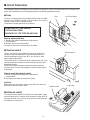
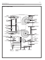
3-1 Prism ass’y removal and disassembly
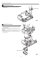
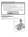
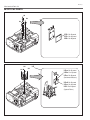
1 Remove 4 hex screws A and take the LCD/Prism ass’y off upward.
2 Remove each 1 screw B and take the Glass Holder, and then pull the
Optical filter, Polarized Glass-Out upwards off. These glasses are mounted
for R, G and B LCD panels respectively.
Note:
To avoid the CG and focus alignments slipping off, please be careful to handle the LCD/Prism ass'y.
A
A
Note:
Do not replace the LCD panel
separately otherwise it can
not obtain proper picture.
A
Polarized GlassOut
B
A
Optical Filter
Fig.3-1
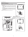
* Glasses should be placed as the
sheet attached side comes to the
LCD panel side.
Fig.3-2
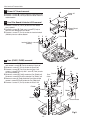
3-2 Polarized glass and optical filter mounting direction
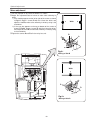
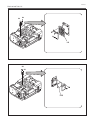
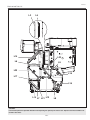
The polarized glasses and optical filters in the prism assembly are installed
as figure below. Please be careful for the mounting.
The polarized glasses are placed as the film attached face comes outside.
The optical filters are placed as the face on which the part no. is printed
comes to the arrow direction as shown in the figure. The optical filters for B
and G panel have films on the both of the faces.
Optical Filter
1AV4Z15Bxxxx
Film
G-Panel
Top
Prism
B-Panel
Polarized Glass-Out
Fig.3-3
Optical Filter
Polarized Glass-Out
G-Panel
Fig.3-4
-14-
Polarized Glass-Out
Optical Filter