1
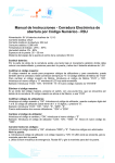
Service Manual
1/94
PS-340, 341
PS-400, 401
1
Index
Index
Technical data
page
3
Special tools
4
01
Chain brake
5
02
Clutch, clutch drum
5
03
Oil pump
6
04
Ignition system
8
05
Starting system
10
06
Carburettor, intake system
11
07
Deko-Valve
12
08
Vibration damping system
13
09
Fuel tank
13
10
Cylinder, piston
14
11
Crankcase, crankshaft
14
12
Checking operations
16
Torques
17
2
Technical data
Model
PS-340/341
PS-400/401
Displacement
3
cm
33
39
39
Bore
mm
37
40
40
Stroke
mm
31
31
31
Rating
kW
1,4
1,7
1,7
2600
2600
2600
11500
12000
12000
Idling
rpms
Allowed max engine speed
with bar and chain
1/min
Gap
Flywheel / Coil
L
r.p.m.
H r.p.m.
Max.
mm
High tension wire legth
Spark plug
NGK
0,2
0,2
0,2
mm
300
300
BPMR-6F
BPMR-6F
BPMR-6F
RDJ-7Y
RDJ-7Y
CHAMPION
Elektrode gap
mm
0,5
0,5
0,5
Fuel tank capacity
Ltr.
0,4
0,4
0,4
0,25
0,25
0,25
1/1
1/1
1/1
mm
3 / 900
3 / 900
Oil tank capacity
Ltr.
Carb. adjustement
Starter rope
L/H
S
H
L
ø / length
Saw chain Terms / Pitch
092
092
092
Low Profil
Low Profil
Low Profil
300
RDJ-7Y
3 / 900
Cutter type
Semi chisel
Gauge
3/8
(9,52)
0.50
(1,3)
30°
3/8
(9,52)
0.50
(1,3)
30°
Sideplate Angle
85°
85°
85°
Cutting Angle
60°
60°
60°
90°
90°
90°
mm
0,65
0,65
mm
4,0
4,0
1
2
Filing Angle
90°
File Guide Angle
Depth Gage Setting
File ø
Kick back Reduction
Cutting length
Drive Link
Sprocket
Semi chisel Semi chisel
3/8
(9,52)
0.50
(1,3)
Drive Link
inch
mm
inch
mm
10°
Depth Gauge /
Depth Gauge /
Bumper Tie Strap Bumper Tie Strap
cm
Count
No of Teeth
type
35/40
35/40
52/56
6
Rim (fixed)
52/56
6
Rim (fixed)
Bumper Tie
Strap
3
Special tools
Puller for oil seals
944 500 870
4
Mounting sleeve
for radial rings
944 500 540
Sealing plate for leakage
test of crankcase
944 603 020 / 944 603 030
Drift for piston pin
Dis- and mounting tools for
drive worm of oil pump
950 500 020
Jarring blow punch
944 603 250
944 500 880
Setting gauge for
ignition armature
944 500 890
Mounting tools for
clutch hub
944 500 690
01 Chain brake
02 Clutch, clutch drum
2
3
1
4
01-02 Replacing the brake band
Remove the sprocket guard from the engine
unit. Release the chain brake by pushing the
lever in direction of the arrow.
Unsrew the five srews and remove the
protection plate (1).
01-02 Replacing the brake band
Lift brake band out of the sprocket guard (2)
and of the hook (3). When fitting a brake band
ensure that the guide piece (4) is installed
correctly in the slot of the sprocket guard.
6
5
7
02-01 Removing the clutch and clutch drum
Block the cylinder unit before removing the
clutch drum or clutch. For this purpose
unscrew the muffler (5) and pass the piston
stopp wedge (6) 944 602 001 into the exhaust
duct of the cylinder.
7
8
02-01 Unscrewing the clutch
To unscrew the clutch use spanner (8) no.
944 500 690.
Caution: Left-hand thread.
If required, the clutch springs (7) have to be
replaced as a complete set.
9
02-03 Checking the clutch drum/sprocket
Clean or renew in the case of contamination or
wear.
02-04 Mounting the clutch drum
Lightly grease the needle bearing (9) prior to
installation.
Tighten the clutch using a torque of 25 Nm.
5
03 Oil pump
1
+
03-01 Adjusting the oil pump delivery
Adjustment is by turning the screw
clockwise
= less chain oil
anti-clockwise = more chain oil.
+
2
03-02 Dismantling the oil pump
Slightly raise the claws from the chain guide
plate (1) and remove the guide plate and the
chain tensioner (2).
3
13
12
03-02 Removing the oil pump
Pull out the oil pump from the crank case and
from the suction line (3).
4
03-02 Mounting the oil pump
When mounting the oil pump, the pin (12)
must be inserted into the hole (13).
7
7
5
6
03-03 Inspecting the oil pump
Remove the retaining ring and the washer (4).
Remove the set screw (5). Remove the oil
pump plunger (6) together with the
compression spring from the housing (7).
6
03-03 Assembling the oil pump
Prior to reassembling the oil pump, liberally
grease the oil pump plunger (6) and the
housing (7) with silicon compound no.
980 007 100.
03 Oil pump
3
9
8
8
03-04 Checking the intake line and the filter
Withdraw the intake line (3) from the
crankcase. Remove the filter (8) from the
intake line for cleaning.
03-04 Greasing the suction line
Prior to the installation of the suction line
grease the line in way of the sealing face (9)
at the crankcase using silicone grease.
10
03-05 Removing the drive worm
Screw the extractor device 950 500 011 in
place for the removal of the drive worm (10).
Caution: Left-hand thread.
Manually remove the worm from the
crankshaft using device 950 500 011.
03-05 Mounting the drive worm
Screw the worm fully into the device.
03-05 Fitting the drive worm
Pass the device over the crankshaft until the
edge (arrow) butts against the crankcase.
7
04 Ignition system
2
1
3
04-01 Removing the spark plug
Pull off the spark plug cap (1) and remove
the spark plug using wrench no.941 716 131.
4
04-01 Checking the spark plug
Connect the spark plug (2) with the cap (1)
and connect to cylinder.
Smartly withdraw the starter rope (3).
Caution: The short-circuit switch (4) must be
in position „I“ (horizontal).
6
5
04-01 Checking the spark plug
If no spark can be produced, try again using
a new spark plug.
Clean or renew contaminated or defective
spark plugs.
04-04 Gaining access to the ignition
armature
Before removing the ignition armature, it is
necessary to remove the handle (5) and the
fan housing (6).
9
8
7
10
04-04 Removing the ignition armature
Disconnect the short-circuit cable (7) from
the ignition armature (8). Remove the screws
(9).
8
04-04 Removing the ignition armature
Hold the ignition cable (10) and unscrew the
ignition armature.
04 Ignition system
12
11
NS
9
11
9
04-04 Mounting the ignition armature
When mounting the ignition armature, the air
gap (11) between the flywheel and the ignition
armature must be set to 0.2 mm using gauge
944 500 890.
04-04 Adjusting the air gap
Insert the adjustment gauge (12) and turn the
marking N/S of the flywheel towards the
ignition armature. Push the ignition armature
tightly against the flywheel and uniformly
tighten the screws (9) using a torque of 3 Nm.
15
14
13
16
17
04-04 Replacing the ignition cable and the
short-circuitcable
Prior to the replacement of these cables it is
necessary to remove the flywheel (13), starter
system (14), carburettor (15) and the bottom
(16).
04-05 Withdrawing the magnet wheel
Immobilise the cylinder unit using the piston
stopping wedge. Screw off the nut (17).Screw
on punch 944 500 880. Strike a jarring blow
to separate the flywheel from the crankshaft.
19
18
04-05 Mounting the flywheel
Clean the crankshaft and the flywheel cone
(18) before mounting the flywheel. Ensure that
the key (19) is seated correctly.
04-05 Tightening the flywheel
Tighten the flywheel using a torque of 20 Nm.
9
05 Starting system
3
4
9
1
2
05-02 Relieving the return spring
Relieve the return spring, before removing
the starting system. For this purpose reel off
the starting rope (1) from the rope drum (2) in
the direction of the arrow.
5
05-02 Removing the starting system
Remove the brake spring (3) and the retaining
ring (4). Carefully take out the rope drum (5)
and remove the disk (6).
8
7
05-02 Coiling the return spring by hand
Engage the eye of the spring over the pin (8)
of the rope drum. Coil the spring (7) in an
anti-clockwise direction.
Grease the spring prior to installation using
grease no. 944 360 000
05-02 Mounting the rope drum
Pass the rope drum over the guide pin on the
crankcase housing and fit the retaining ring (4)
to prevent the drum from falling out.
Apply silicone paste to the starter ratchet (9)
prior to installation.
1
05-02 Coiling the starter rope
Coil the starter rope (1) as far as possible on
the drum. Hold the rope tight and together
with the drum turn 2 - 3 turns in the direction
of the arrow to pretension the return spring.
10
05-02 Checking the return spring
To check the pretensioning of the spring,
withdraw the rope completely and hold it in the
extended position. It must now be possible to
turn the rope drum by at least another half
turn. Reduce the preload tension, if this is not
possible.
06 Carburettor/intake system
3
2
1
06-01 Adjusting the carburettor
For basic adjustment screw in both screws L
and H against the stop. Then back off
the idling jet
(1) by 1 - 1 1/4 turns and
the high speed jet (2) by 1 - 3/4 turn.
06-01 Idling adjustment
When during idling the engine speed is too
high (moving chain) or too low (engine stalls),
correct the setting of the idling screw S
(speed) accordingly.
7
12
4
6
11
10
5
8
06-02 Removing the carburettor
Unscrew the nuts. Disengage the throttle
linkage (4) at the lever of the throttle valve
shaft. Remove the choke lever (5). Separate
the fuel line (6) and the impulse lead (7) from
the carburettor.
9
06-03 Control side of carburettor
Unscrew the cover (8) and remove the control
diaphragm (9) and the gasket (10). Remove
screw (11). The control set (12) comprises the
inlet needle, rocker arm, spring and shaft.
13
16
17
15
06-03 Aligning the rocker arm
Following installation the rocker arm (13) must
be aligned parallel with the carburettor bottom.
Gauge 956 008 000
14
06-04 Pump side of carburettor
Unscrew the cover (14) and remove the joint
(15) and the pump diaphragm (16).
Carefully remove the fuel filter (17) from the
carburettor body for cleaning.
11
06 Carburettor/intake system
1
2
06-08 Removing the bottom
The bottom, together with the intermediate
flange, is attached by means of two screws
to the cylinder and by means of one screw
(1) to the housing.
06-08 Removing the choke lever
Withdraw the choke lever (2) from its guide in
the bottom.
5
4
3
3
06-08 Removing the short-circuit switch
Slightly lift the short-circuit switch (3) and
remove it from the bottom.
Withdraw the cable (4) from the switch
housing.
2
06-08 Bottom with installation parts
Choke lever (2), short-circuit switch (3) and
joint (5).
7
8
6
06-08 Removing the intermediate flange
Following the removal of the bottom, the
intermediate flange, (6) together with the
joints(7 and 8), can be removed.
12
07-01 Checking the Decompression valve
Remove top cover (cylinder/air filter). Unscrew
the deco valve. Clean or renew in the case of
contermination or wear.
Tighten the deco valve using a torque of 8 Nm.
4
08 Vibration damping system / 09 Fuel tank
2
4
1
3
08-02 Vibration damper „CS“
Two of the total four vibration dampers (1/ 2)
are arranged at the crankcase clutch side
(CS).
08-02 Vibration damper „MS“
The other two vibration dampers (3 / 4) are
arranged at the crankcase magnet side (MS).
2
5
3
1
6
08-02 Replacing the vibration dampers
For replacing the vibration dampers and for
removing the fuel tank, unscrew all four
screws and withdraw the bushes (1, 2, 3).
09-01 Fuel tank
Arranged in the fuel tank are the ventilation
valve (6) and the intake line (5) incorporating
the fuel filter.
7
6
8
09-02 Replacing the ventilation valve
For cleaning and replacing the ventilation
valve (6) remove the valve from its seat in the
fuel tank (7).
09-05 Checking the fuel filter
Remove the screw plug and pull out the filter
(8) from the fuel tank. For cleaning and
replacing withdraw the filter from the intake
line.
13
10 Cylinder, piston / 11 Crankcase
2
1
3
10-01 Removing the retaining rings
Using a pair of pointed pliers remove the two
retaining rings (3) from the piston.
Note: Do not displace the connecting rod (6)
after the removal of the cylinder, as otherwise
the loose rollers (7) of the connecting rod
bearing would fall out.
10-01 Removing the cylinder
Remove the four attachment screws (1) of
the cylinder (2). Withdraw the cylinder from
the crankcase and piston.
11
6
5
7
4
10
10-01 Removing the piston
Press out the gudgeon pin (4) in the direction
of the arrow. Separate the piston (5) from the
piston rod with the permanently fixed needle
bearing (6) for the gudgeon pin.
11-02 Replacing the radial rings
Pass the device (10), part no.944 500 870
over the crankshaft and screw it tightly into the
rubber lip of the radial ring. Hold the device
and withdraw the radial ring by screwing in the
screw (11).
S
9
8
S
11-03 Unscrewing the crankcase screws
The two crankcase halves KS/MS are screwed
together by means of six screws (S).
14
11-03 Dismantling the crankcase
After the removal of the screws, the two
halves of the crankcase (8, 9) can be
separated by lightly tapping with a plastic
hammer.
11 Crankcase/Crankshaft
6
7
12
13
19
11-03 Removing the needle bearing
Prior to the removal of the needle bearing
(12), remove the retaining ring (13) using a
suitable pair of pliers.
Note: Crankcases supplied as spare parts
are already fitted with bearings/radial rings.
11-03 Mounting the connecting rod bearing
rollers
Apply grease to the crankpin of the crankshaft
(19) and install the 12 rollers (7). Pass the
connecting rod (6) over the rollers.
9
8
15
15
16
19
17
14
11-03 Aligning the suction line and seal for
the crankcase
Prior to assembling the crankcase halves,
place the gasket (14) over the locating pins
(15/15). Install the chain oil suction line (16).
11-03 Assembling the crankshaft and
crankcase
Install the crankshaft (19) in the crankcase (9).
Fit the mounting bush (17), no. 944 500 540,
to the crankshaft and mount the crankcase (8).
20
5
21
18
11-03 Assembling the crankcase halves
Install and tighten the screws using a torque of
10 Nm.
11-03 Assembling the cylinder and piston
Place the fork (21) on the crankcase and
mount the piston. Align the piston ring (5) and
compress it using the tension band (18). Pass
the cylinder (20) over the piston while pushing
the tension band downwards.
15
12 Checking operations
12-01 Tightening torque
Use the torque wrench, part no. 950 232 000,
for tightening the screws, flywheel and the
clutch.
12-02 Checking the ignition system
Use the tester, part no.956 010 300, for
checking the ignition system and the spark
plug.
2
3
1
12-03 Checking the carburettor
Separate the fuel line (1) from the connecting
nipple (2) of the carburettor and connect the
pressure-tester (3), part no. 956 004 000.
12-03 Checking the carburettor (continued)
Subject the carburettor to a pressure test
using a max. pressure of 0.5 bar.
4
12-05 Checking the crankcase
For pressure-testing the crankcase, block the
exhaust duct with plate 944 603 010. Screw
the plate 944 603 020, with the connection
nipple for the pressure tester, to the intermediate flange. Block the impuls line (4).
16
12-05 Checking the crankcase
Subject the crankcase to a pressure-test using
a max. pressure of 0.5 bar.
Torques
Model
PS-340/341
PS-400/401
Muffler
8,0 + 1,0
Crankcase
10,0 + 1,0
Cylinder
6,0 ± 0,5
Ignition coil
3,0 + 1,0
Turbular handle
3,0 ± 0,5
Rubber buffer
2,5 ± 0,5
Intermediate flange
6,0 + 0,5
Carburator
2,5 + 0,2
Clutch bub
25,0 ± 2,5
Flywheel
20,3 - 2,7
Spark plug
15,0 ± 1,0
17
18
DOLMAR GmbH
Postfach 70 04 20
D-22004 Hamburg
Germany
http://www.dolmar.com
Änderungen vorbehalten
Form: 995 721 020 (1.94 GB)