1
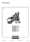
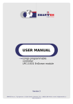
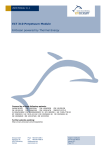
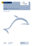
Evaluation Kits
EVA 100 and EVA 105
User Manual V1.7
April 2007
Revision History
The following major modifications and improvements have been made to the first version of
the document (EVA 100 User Manual V1.0):
No
Subject (major change since last version)
V1.1
No major changes
V1.2
Chapter “Operating Modes” added, chapter “Getting Started” revised
V1.3
Chapter “Description of On-board indicators” revised
V1.4
New version for TCM 120 support
V1.5
EVA 105 included (US version with 110V power supply)
V1.6
Batteryless pushbutton transmitter PTM 100 is replaced by type PTM 200
V1.7
STM100 replaced by STM110, EVA Mon replaced by WinEtel software
Published by EnOcean GmbH,
Kolpingring 18a, 82041 Oberhaching
© EnOcean GmbH
All Rights Reserved
Attention please!
The EVA evaluation kit is for laboratory use only!
This information describes the type of component and shall not be considered as assured characteristics. No
responsibility is assumed for possible omissions or inaccuracies. Circuitry and specifications are subject to change
without notice. For the latest specifications, refer to the EnOcean website: http://www.enocean.com.
As far as patents or other rights of third parties are concerned, liability is only assumed for components, not for
applications, processes and circuits implemented within components or assemblies.
EnOcean does not assume responsibility for use of devices described and limits its liability to the replacement of
devices determined to be defective due to workmanship. Devices or systems containing RF components must itself
meet the essential requirements of the local legal authorities.
EnOcean GmbH does not recommend the use of its products in life support applications and will not knowingly sell its
products for use in such applications unless it receives an adequate "products liability indemnification insurance
agreement".
Components of the modules are considered and should be disposed of as hazardous waste. Local, government
regulations are to be observed.
©EnOcean GmbH
Page 2 of 12
User Manual EVA 100, V1.7
Table of Contents
1. EVA General Kit Description .......................................................................................4
2. Scope of EVA 100 Kit Supply and Ordering Information..................................................5
2. Scope of EVA 105 Kit Supply and Ordering Information..................................................6
4. On-board Overview EVA 110 (Board) ..........................................................................6
5. Board Dimensions and Environmental Conditions ..........................................................7
6. Description of On-board Connectors ............................................................................7
7. Description of On-board Indicators..............................................................................8
8. Description of On-board Switches ...............................................................................8
9. Description of RCM Operation Modes ...........................................................................9
10. Getting Started .................................................................................................... 10
11. Changing the Operation Mode ................................................................................ 10
12. Serial Interface (RCM 120 Operating Mode 0 / TCM 120 mode) ................................... 11
13. Application Monitor EVA-MON ................................................................................. 11
14. TCM Monitor ........................................................Fehler! Textmarke nicht definiert.
15. EVA 110 Circuit Diagram ....................................................................................... 11
©EnOcean GmbH
Page 3 of 12
User Manual EVA 100, V1.7
1. EVA General Kit Description
EVA 100 and EVA 105 are evaluation kits to support the development of applications based on
the EnOcean RCM receiver modules and the TCM transceiver modules. The kits support a
quickly evaluation of all RCM receiver operation modes as well as a quite easy setting-up
operation of the receiver side when EnOcean transmitter modules are evaluated.
Figure: EVA EnOcean Evaluation Kit
PTM Push-Button Powered Transmitter
•
The PTM radio transmitter modules from EnOcean enable the implementation of
wireless remote controls without batteries. Power supply is provided by a built-in
pressure energy converter.
•
Key applications are on-wall mountable flat rocker switches or handheld remote
controls.
STM 110 Solar Powered Transmitter
•
The extremely power saving RF transmitter module STM 110 of EnOcean enables the
realization of wireless and maintenance free sensors.
•
Power supply is provided by a small solar cell. An integrated energy store allows
unrestricted functionality for several days in total darkness.
•
Three 8 bit A/D converter inputs and 4 digital inputs facilitate multifunctional detector
systems, based on application specific passive sensing components. This allows easily
and comfortable monitoring of position, temperature, illumination, pressure, etc. - or
simply supervising voltages or currents.
©EnOcean GmbH
Page 4 of 12
User Manual EVA 100, V1.7
RCM 110 Receiver Functionalities
•
Logic output signals controlled by EnOcean PTM Switches: Switching (on/off, 1 to 4
channels) or Dimming (PWM 50 kHz with switch-off value memory)
•
Scene selection control (6 light scenes, all-on/off)
•
Learning procedure for EnOcean PTM transmitters, easy to operate
RCM 120 Receiver Functionalities
•
9600 bps serial data link from all EnOcean RF transmitters (e.g. PTM, STM). This
interface facilitates any desired actor functionality by the user
•
Logic output signals controlled by EnOcean PTM Switches: Tubular Motor Control
(up/down with slat acting, 1 or 2 motors) or Pushbutton (pressed/released)
•
Learning procedure for EnOcean transmitters, easy to operate (optional within serial
data link)
TCM 120 Receiver Functionalities (TCM 120 not contained in EVA 100 / EVA 105):
•
9600 bps bi-directional serial data link from all EnOcean RF transmitters (e.g. PTM,
STM) and to all EnOcean radio receivers.
The detailed functionality of all EnOcean radio modules are described in the actual
documentation corresponding to the versions of the used modules.
2. Scope of EVA 100 Kit Supply and Ordering Information
Type
EVA 100
Content / Description
Ordering Code
1) Short User Instruction “Get Started”
S3004-G100
2) EVA 110: EnOcean Evaluation Board (PCB)
3) 230V/50Hz wall power supply
4) CD with WinEtel SW application, and user documentation
5) PTM 200: EnOcean Pushbutton Transmitter with Test
Rocker
6) STM 110: EnOcean Sensor Data Transmitter Module with
Solar Cell
7) RCM 110: EnOcean Receiver Module
8) RCM 120: EnOcean Receiver Module
9) Equipment case
©EnOcean GmbH
Page 5 of 12
User Manual EVA 100, V1.7
2. Scope of EVA 105 Kit Supply and Ordering Information
Type
EVA 105
Content / Description
Ordering Code
1) Short User Instruction “Get Started”
S3004-G105
2) EVA 110: EnOcean Evaluation Board (PCB)
3) 120V/60Hz wall power supply
4) CD with WinEtel SW application, and user documentation
5) PTM 200: EnOcean Pushbutton Transmitter with Test
Rocker
6) STM 110: EnOcean Sensor Data Transmitter Module with
Solar Cell
7) RCM 110: EnOcean Receiver Module
8) RCM 120: EnOcean Receiver Module
9) Equipment Case
4. On-board Overview EVA 110 (Board)
Figure: On-board connectors, switches and indicators
©EnOcean GmbH
Page 6 of 12
User Manual EVA 100, V1.7
5. Board Dimensions and Environmental Conditions
-
The dimensions of the EVA board are 180 x 80 x 23 mm
-
The EVA evaluation board has been designed for laboratory use only (room
temperature, indoor)
6. Description of On-board Connectors
Symbol
Function
Adaptor
Female jack for power supply
RCM/TCM
Female header for plug-in RCM or TCM module
(Pin 1 is module antenna side)
Test
Connector
Female header connected directly to module
leads
Vcc
Jack to disconnect the power supply to the
inserted module
GND
GND
Ground connectors for functional control
outputs
Operational
characteristics
14 - 30 V,
100 mA max.
Bridge
R0
R1
R2
R3
Functional control outputs directly connected
to the OUT_0..3 output pins of inserted
module
Open collector
outputs:
35 V max.,
100 mA max.,
100 mW max. each
GND
EVG
Analog output to drive an Electronic Control
Gear (RCM 110, Mode 5 only)
0 to 10 V, 20 mA max.
GND
PWM
50 kHz PWM output (RCM 110, Mode 5 only)
5 V TTL, 20 mA max.
RS232
DB9 female serial interface connector to PC
• RCM 120, Operating Mode 0 (Rx)
• TCM 120 (Rx an Tx)
12 V
TCM RCM
Selector for RCM or TCM module operation
Bridge
©EnOcean GmbH
Page 7 of 12
User Manual EVA 100, V1.7
7. Description of On-board Indicators
Symbol
Function
Power
Power supply indicator
Signal
indicator
Indication output of received signal strength
of all 868.3 MHz signals (peak detection)
• Red: No Radio Signal
• Yellow: Weak Radio Signal
• Green 0..2: Strong Radio Signal
I0
I1
I2
I3
Status indicator of functional control outputs.
Also indicate current learning mode status
(see RCM 110/120 User Manual “Learning of
radio transmitters”)
LMI
Learning Mode indication output: LMI is
shining in the learning mode phase
8. Description of On-board Switches
Symbol
Function
MODE
Encoding switch for operation mode selection of RCM 110/120 (ON is active
GND connection):
switch 1 = CODE_0
switch 2 = CODE_1
switch 3 = CODE_2
The operation mode is defined with the pin status at power-up. A change of
the operation mode is possible with cleared ID memory only (see CLR).
LRN(Grey)
Pushbutton to enter transmitter learning mode: Teaching of switch rockers
and sensor modules into the receiver by triggering the transmitter telegram
at least one time
SSLM(Black) Pushbutton to enter scene switch learning mode
CLR(Red)
Pushbutton to clear the receiver ID and scene memory (all learned switch
rockers, sensors and scene switches)
©EnOcean GmbH
Page 8 of 12
User Manual EVA 100, V1.7
9. Description of RCM Operation Modes
Mode
switch
1
2
RCM
Function
3
0 0
0
RCM 120 Serial data link
(9600 bps, 1 start bit, 1 stop bit).
1 0
0
RCM 120 Pushbutton
0 1
0
RCM 110 Switching 1 channel
0 1
0
RCM 120 Turbular motor control 2-channel
1 1
0
RCM 110 Switching 2 channel
0 0
1
RCM 110 Switching 4 channel
1 0
1
RCM 110 Dimming PWM 50 kHz, switch off
value memory
0 1
1
RCM 120 Tubular motor control
1 1
1
RCM 110 Test / not documented
RCM 120
Output
Indicator I0 – I4
on-board connectors
I0, R0: Serial data open collector
RS232: Serial data (Use PC Software EVAMON contained on CDROM)
One-to-one copy of pushbutton actions
“O-button pressed/released” at I0, R0 and
“I-button pressed/released” at I1, R1
Logic switching state “on/off” at I0, R0
when pushing the switch rockers
Channel 1:
“Open/Up” at I0, R0
“Close/Dn” at I1, R1
Channel 2:
“Open/Up” at I2, R2
“Close/Dn” at I3, R3
Logic switching state “on/off” at I0, R0
(Ch1) and I1, R1 (Ch2) when pushing the
switch rockers
Logic switching state “on/off” at I0-4, R0-4
(Ch1-4) when pushing the switch rockers
I0, R0, PWM: Inverted Output PWM
EVG: Output 1-10V to connect external
Dimming EGC
“Open/Up” at I0, R0
“Close/Dn” at I1, R1
The detailed functionality of the EnOcean transmitter and receiver modules is described in the
documentation corresponding to the versions of the used modules.
©EnOcean GmbH
Page 9 of 12
User Manual EVA 100, V1.7
10. Getting Started
1. Carefully read the User Manuals on the EVA-CD
2. Unpack the EVA-PCB from the suitcase and put it on a non conductive flat base
3. Plug the RCM 110 or RCM 120 receiver module into the RCM 100 connector. Remark:
RCM connector pin 1 is at antenna cable side
4. Select the desired receiver operation mode by the MODE dip switch. Please refer to
table “Description of Operation Modes” and the actual documentation of RCM 110/120.
(Example: For “Switching 1 channel” use RCM 110 with switch 1 off, switch 2 on, switch
3 off)
5. Connect the power supply
6. Press the CLR pushbutton until LMI is on (Remark: The operation mode is defined with
pin status at power up, a change of operation mode is possible with cleared ID memory
only. So this initial CLR procedure avoids initialization errors in cause of not
cleared ID memories)
7. After I0 starts blinking, EnOcean transmitters can be learned by sending a telegram.
(Example “switching 1 channel”: Operate the PTM transmitter with mounted demorocker one time). For learning confirmation I0 is on for 4 seconds
8. Press pushbutton LRN to change to the next channel (in multi channel modes only, then
I1 is blinking next) or to leave learn mode (LMI is off)
9. When LMI is off, the application is ready for operation. (Example “Switching 1 channel”:
Operating the PTM switches on/off I0-LED and the corresponding R0 output)
10. For changing the operation mode again, please disconnect the power supply and
continue with step 4
11. Changing the Operation Mode
1. Press the CLR pushbutton until LMI is on (Remark: The operation mode is defined with
pin status at power up, a change of operation mode is possible with cleared ID memory
only. So this CLR procedure avoids initialization errors in cause of not cleared ID
memories)
2. Disconnect the power supply
3. Select the new desired receiver operation mode by the MODE dip switch
4. Connect the power supply
5. Press the LRN pushbutton until LMI is on. After I0 starts blinking, EnOcean transmitters
can be learned by sending a telegram.
©EnOcean GmbH
Page 10 of 12
User Manual EVA 100, V1.7
12. Serial Interface (RCM 120 Operating Mode 0 / TCM 120 mode)
When the TCM 120 transceiver is used or the RCM 120 receiver is in mode “Serial Interface”, it
transfers out data blocks of information from the received radio telegrams. All received
EnOcean-telegrams will be transferred. The data block format is explained in detail in the user
manuals of TCM 120 and RCM 110/120.
By connecting the on-board RS232 DB9 connector through a not crossed connector cable to a
serial PC port, the received data can be directly operated by the PC through the application
WinEtel which is scope of EVA 100 supply.
When the TCM RCM bridge is set to TCM mode, the serial connection is bi-directional. Then it is
also possible to transmit telegrams. For a detailed description of the WinEtel application please
refer to the HELP menu in WinEtel.
13. Application WinEtel
Please start the setup program from CD-Rom and follow instructions.
Please refer to the HELP menu in WinEtel for a detailed description of functionalities.
15. EVA 110 Circuit Diagram
See next page
©EnOcean GmbH
Page 11 of 12
User Manual EVA 100, V1.7
©EnOcean GmbH
Page 12 of 12
User Manual EVA 100, V1.7