1
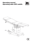
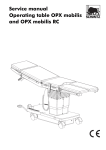
Service manual
Partura delivery bed®
This service manual contains instructions how to carry out
repairs on the Partura delivery bed.
2
Service manual
Table of contents
Introduction . . . . . . . . . . . . . . . . . . . . . . . . . . . . . . . . . . . . . . . . . . . . . . . . . . . . . . . . . . . . . . . . . . . . . . . . . . . .
About this service manual . . . . . . . . . . . . . . . . . . . . . . . . . . . . . . . . . . . . . . . . . . . . . . . . . . . . . . . . . . . . . . .
Symbols used in the text . . . . . . . . . . . . . . . . . . . . . . . . . . . . . . . . . . . . . . . . . . . . . . . . . . . . . . . . . . . . . . . .
Safety instructions . . . . . . . . . . . . . . . . . . . . . . . . . . . . . . . . . . . . . . . . . . . . . . . . . . . . . . . . . . . . . . . . . . . . .
Intended use . . . . . . . . . . . . . . . . . . . . . . . . . . . . . . . . . . . . . . . . . . . . . . . . . . . . . . . . . . . . . . . . . . . . . . . . .
5
5
6
7
7
Description of the delivery bed . . . . . . . . . . . . . . . . . . . . . . . . . . . . . . . . . . . . . . . . . . . . . . . . . . . . . . . . . . . . . . 9
Repairs on the main section . . . . . . . . . . . . . . . . . . . . . . . . . . . . . . . . . . . . . . . . . . . . . . . . . . . . . . . . . . . . . . .
How to remove and re-attach the claddings . . . . . . . . . . . . . . . . . . . . . . . . . . . . . . . . . . . . . . . . . . . . . . . . .
How to replace the control units . . . . . . . . . . . . . . . . . . . . . . . . . . . . . . . . . . . . . . . . . . . . . . . . . . . . . . . . .
How to replace the connecting box . . . . . . . . . . . . . . . . . . . . . . . . . . . . . . . . . . . . . . . . . . . . . . . . . . . . . . .
How to replace the motors for shock position adjustment . . . . . . . . . . . . . . . . . . . . . . . . . . . . . . . . . . . . . . .
How to replace the motors for height adjustment 18
How to replace the motor for adjustment of the seat section . . . . . . . . . . . . . . . . . . . . . . . . . . . . . . . . . . . . .
How to replace the motor for adjustment of the back section . . . . . . . . . . . . . . . . . . . . . . . . . . . . . . . . . . . . .
11
11
14
16
17
20
21
Repairs on the foot section . . . . . . . . . . . . . . . . . . . . . . . . . . . . . . . . . . . . . . . . . . . . . . . . . . . . . . . . . . . . . . . . 23
How to remove and re-attach the covering plate of the foot section . . . . . . . . . . . . . . . . . . . . . . . . . . . . . . . . 23
How to replace the motor for adjustment of the foot section . . . . . . . . . . . . . . . . . . . . . . . . . . . . . . . . . . . . . . 24
General maintenance works . . . . . . . . . . . . . . . . . . . . . . . . . . . . . . . . . . . . . . . . . . . . . . . . . . . . . . . . . . . . . . . 27
How to replace the castors . . . . . . . . . . . . . . . . . . . . . . . . . . . . . . . . . . . . . . . . . . . . . . . . . . . . . . . . . . . 27
How to replace the levelling feet . . . . . . . . . . . . . . . . . . . . . . . . . . . . . . . . . . . . . . . . . . . . . . . . . . . . . . . 28
Checking the electrical safety . . . . . . . . . . . . . . . . . . . . . . . . . . . . . . . . . . . . . . . . . . . . . . . . . . . . . . . . . . . . . .
Carrying out the measurements . . . . . . . . . . . . . . . . . . . . . . . . . . . . . . . . . . . . . . . . . . . . . . . . . . . . . . . .
Documentation and evaluation of the tests . . . . . . . . . . . . . . . . . . . . . . . . . . . . . . . . . . . . . . . . . . . . . . . .
Visual inspection . . . . . . . . . . . . . . . . . . . . . . . . . . . . . . . . . . . . . . . . . . . . . . . . . . . . . . . . . . . . . . . . . . .
Measuring the resistance of the protective conductor. . . . . . . . . . . . . . . . . . . . . . . . . . . . . . . . . . . . . . . . .
Measuring the equivalent of the leakage current to ground . . . . . . . . . . . . . . . . . . . . . . . . . . . . . . . . . . . .
29
29
30
30
30
32
Spare parts lists . . . . . . . . . . . . . . . . . . . . . . . . . . . . . . . . . . . . . . . . . . . . . . . . . . . . . . . . . . . . . . . . . . . . . . . . 37
Circuit diagrams. . . . . . . . . . . . . . . . . . . . . . . . . . . . . . . . . . . . . . . . . . . . . . . . . . . . . . . . . . . . . . . . . . . . . . . . 39
After-sales service . . . . . . . . . . . . . . . . . . . . . . . . . . . . . . . . . . . . . . . . . . . . . . . . . . . . . . . . . . . . . . . . . . . . . . . 42
Partura delivery bed® – EDITION
02-00-GB
ID.-Nr.: 02006636
3
Table of contents
4
Service manual
Introduction
About this service manual
In this paragraph you will find information about the layout of this service manual and explanations concerning
the marks and symbols used in the text.
This service manual is to be read and observed by any
person authorized to carry out work with and on the delivery bed, such as service, inspection or maintenance.
This service manual contains instructions how to carry out
repairs on the Partura delivery bed
In addition to the operating manual and to the mandatory
rules and regulations for accident prevention effective in
the user’s country and on the site of use, the generally acknowledged technical rules for safe and professional
work are also to be observed.
Our products are constantly being improved; that is why
design-related modifications carried out after the printing
of this service manual could not be taken into consideration. In case of any question, please contact our service
team.
Partura delivery bed® – EDITION
02-00-GB
ID.-Nr.: 02006636
5
Introduction
Symbols used in the text
In this service manual following designations or symbols
are used to point out pieces of information of particular
importance.
g
v
a
6
Danger!
This symbol will appear wherever safety hints
are designed to protect people from physical
harm. The symbol stands for imminent danger
of death or serious injury.
Caution!
This symbol will appear where situations are
described which might be dangerous, and
which might inflict slight injuries.
h
This symbol will appear in front of additional
helpful pieces of advice.
• A dot in front of the text means:
This is what you have got to do.
– A dash in front of the text means:
This is part of an enumeration.
Attention!
This symbol will appear in front of warning hints
which shall prevent the table or other equipment from being damaged.
Service manual
Safety instructions
The delivery bed has been constructed according to stateof-the-art standards and to the acknowledged rules for
safety engineering. Nevertheless, its use may inflict danger to life or physical safety of the user or of third parties,
or impairment to the delivery bed or to other material assets.
Observe the intervals prescribed or stated in the operating manual for periodical check-ups!
Do not use the delivery bed unless in technically perfect
condition and only for its intended use, with regard to
safety and possible dangers, and observing the operating
manual!. It is most important to have any malfunction
which may affect the safety of the appliance eliminated
immediately!
Work on the electrical system and equipment of the delivery bed may only be carried out by a skilled electrician, or
by specially instructed persons under the supervision and
guidance of a skilled electrician, and in accordance with
the applicable rules and regulations for electrical engineering.
Always keep the operating manual at hand at the site of
use of the delivery bed!
Any safety devices removed for maintenance or repair
purposes must be refitted and checked immediately upon
completion of the maintenance and repair work.
In addition to the operating manual, observe the general
rules implied by the law and all other mandatory regulations for accident prevention and environmental protection!
Do not carry out any modifications, extensions or reconstructions of the delivery bed which might affect its safety
without the manufacturer’s approval!
Spare parts must comply with the technical requirements
specified by the manufacturer. This is always guaranteed
when using original spare parts.
For the execution of maintenance work, tools and workshop equipment adapted to the task on hand are absolutely indispensable.
The electrical safety must especially be checked after carrying out the following tasks:
– replacement of motors and
– replacement of control units.
Ensure that all running and process materials as well as
parts exchanged are disposed of safely and with minimum environmental impact!
Intended use
The delivery bed is designed exclusively for positioning
parturient women before and during the process of childbirth. Any use apart or beyond this, e. g. as a patient
transport stretcher or as an operating table, is not intended. The manufacturer cannot be held liable for any dam-
Partura delivery bed® – EDITION
02-00-GB
age resulting from such non-intended use, which would
be entirely at the user’s risk.
Intended use also means following the operating manual
and complying with the conditions for inspection and
maintenance.
ID.-Nr.: 02006636
7
Introduction
8
Service manual
Description of the delivery bed
Infusion rod
Cushion
(accessory)
Leg support
Back section pad
Back rest with
handle bar
Seat section pad
Back rest
Rear
Rinsing basin
(accessory)
Handle
Foot section pad
Hand-held
control unit
Handle
Double-action
pedal
Front
Main section
Fork
Foot section
Double-action pedal
In the following manual the terms left-hand, right-hand,
front and rear are used as seen by a person sitting on the
bed and facing the foot section.
Partura delivery bed® – EDITION
02-00-GB
ID.-Nr.: 02006636
9
Description of the delivery bed
10
Service manual
Repairs on the main section
How to remove and re-attach the claddings
Many repair works on the delivery bed can only be carried out after the claddings have been removed. In the
following it is described how to remove and re-attach the
claddings.
• Loosen the screws on top and at both sides of the cladding and pull the cladding off to the rear.
After finishing the repairs, the cladding has to be re-attached.
How to remove the upper rear cladding
How to re-attach the upper rear cladding
Proceed in reverse order to re-attach the cladding.
• Put the cladding back in position and refasten the
screws on top and at both sides of the cladding.
• Refix the lower plate of the fixing clamp for the back
rest with the screws.
• Unscrew the screws at the lower plate of the fixing
clamps for the back rest and remove it.
How to remove the upper front cladding
As soon as the upper rear cladding has been removed,
the front cladding can be detached. Normally it is sufficient to detach the cladding only, without the need to
loosen the cables.
• Unscrew the fastening screws on top of the cladding
and lift the cladding off.
• Let the cables follow and put the cladding sheet carefully down on the fork.
Partura delivery bed® – EDITION
02-00-GB
If the cladding sheet has to be removed completely, in order to be replaced, or in order to replace the motors for
adjustment of the seat or back sections, proceed as follows:
• Compress the strain relieves from the inside and push
them out of the elongated holes of the cladding sheet.
• Unplug all cables which are led through the cladding
sheet from their connections and pull the cables and
their connectors through the elongated holes to the
outside.
• Disconnect the two hand-held control units with cable
connection from the left and right hand sockets.
ID.-Nr.: 02006636
11
Repairs on the main section
• Loosen the fixing screws of the sockets for the handheld control units and lift the sockets off.
How to re-attach the upper front cladding
In order to re-attach the cladding, proceed in reverse order.
If the cables have been removed completely, they have to
be passed through the cladding sheet as described in the
following, otherwise, the next two steps can be omitted.
• Fasten the sockets for the hand-held control units with
screws on the cladding sheet and plug the cables of
the two hand-held control units into the left and right
hand sockets.
• Pass the connectors and cables from the outside
through the elongated holes of the cladding sheet, put
the strain relieves onto the cables and push the strain
relieves into the elongated holes.
• Put the cladding sheet back into place, pull the cables
to the inside and screw in the fastening screws on the
top surface.
How to remove the lower rear cladding
• Deposit the cladding sheet behind the delivery bed.
The lower rear cladding can be detached as soon as the
upper rear cladding has been removed.
Normally, the connector shoes at the current supply cable
do not need to be pulled off.
g
How to re-attach the lower rear cladding
Danger!
Electric shocks are dangerous to life. Disconnect the delivery bed from the mains before detaching the lower rear cladding.
• Loosen 3 screws on each side of the cladding sheet
and the two bottom rear screws at the cladding sheet.
12
In order to re-attach the cladding, proceed in reverse order.
• Put the cladding sheet back into place, fasten the two
bottom rear screws and 3 screws on each side of the
cladding sheet.
Service manual
• Lift the cladding sheet out, bottom side first.
How to remove the lower front cladding
How to re-attach the lower front cladding
• Raise the delivery bed into maximum height, if possible. If this is not possible, the upper front cladding has
to be removed.
a
Attention!
Attach the lower front cladding, or remove it
completely in order to avoid scratching the
cladding sheet, when removing the lower front
cladding.
In order to re-attach the cladding, proceed in reverse order.
• Put the cladding sheet back into place, fasten the two
bottom front screws with stoppers and the screws at
the bottom of the left and right hand sides of the cladding sheet.
• Loosen the two front screws with stoppers and the
screws at the bottom of the left and right hand sides of
the cladding sheet.
Partura delivery bed® – EDITION
02-00-GB
ID.-Nr.: 02006636
13
Repairs on the main section
How to replace the control units
The Partura delivery bed is equipped with two control
units. The left hand control unit marked KOM 13 and the
right hand control unit marked KOM 24 are each fixed to
one of the guide pillars. In order to replace one of the
control units, the upper rear cladding has to be removed
first.
Preparation
• Detach the upper rear cladding. Details can be found
under “How to remove the upper rear cladding” on
page 11.
How to remove the control unit
KOM 24
KOM 13
Connecting box
h
The markings on the connectors and on the
control unit must coincide.
• Turn the connectors anticlockwise using the special
tool and pull all the plugs out.
As soon as all connectors have been pulled out of one of
the control units, the control unit can be removed. The
control units are fixed with screws to the left and right
hand guide pillars.
• Cut the laces.
h
Mark the cables with a felt-tip pen when unplugging them from the control unit.
Screws
• Pull all connectors out of the control unit with the aid
of the special tool.
• Loosen the two screws at the head-end side of the control unit, shift it to the left and lift the control unit out to
the front.
14
Service manual
a
How to install the control unit
Installation of a new control unit is effected in reverse order.
• Insert a new control unit passing the holes at its headend side over the fastening screws and shifting it to the
right. Fasten the screws.
a
Attention!
The cables which lead to the motor must not be
installed together with the control cables. The
control cables are to be installed above the control units.
• If possible, install the cables as before and fix the
loose cables with a lace.
Final tasks
Attention!
The connectors for the control unit are
equipped with gaskets. If connectors are
mounted without the gaskets having been
greased, they cannot be dismounted without
difficulty. Therefore it is necessary to grease the
gaskets before the assembly or to remove the
gaskets completely, so that the plugs can be released later.
• Check the mechanical functions and the electrical
safety. Details can be found under “Checking the electrical safety” on page 29.
• Reassemble the upper cladding.
The delivery bed is operative again.
• Plug the connectors marked beforehand into the sockets of the control unit and make the bayonet catch engage with the aid of the special tool.
Partura delivery bed® – EDITION
02-00-GB
ID.-Nr.: 02006636
15
Repairs on the main section
How to replace the connecting box
The hand-held control units are connected to a connecting box via the D-Sub-connectors in the upper front cladding sheet.
The pulses emitted by the hand-held control units are directed to the connecting box and from there, to both control units. The connecting box is fixed to the fastening
sheet on the right hand guide pillar.
In order to replace the connecting box, the upper rear
cladding has to be removed first.
• Unscrew the fastening screws at the right hand side of
the connecting box and detach the connecting box
from the fastening sheet.
How to install the connecting box
The new connecting box is adjusted and fixed in reverse
order.
• Adjust the connecting box so that the two sockets point
upwards and the dummy plug, downwards.
Preparation
• Remove the upper rear cladding. Details can be found
under “How to remove the upper rear cladding” on
page 11.
• Position the fastening holes of the connecting box over
the holes for the screws in the fastening sheet and
screw the fastening screws in.
• Insert the connectors for the hand-held control units
and for the control units into the connecting box. Details can be found in the above drawing.
• Check the functions of the delivery bed.
How to remove the connecting box
Final tasks
• Check the mechanical functions and the electrical
safety. Details can be found under “Checking the electrical safety” on page 29.
• Reassemble the upper cladding.
The delivery bed is operative again.
KOM 13
Dummy plug
KOM 24
Hand-held
control unit
• Unplug all connectors from the sockets of the connecting box with the aid of the special key.
16
Service manual
How to replace the motors for shock position adjustment
The Partura delivery bed is equipped with 2 motors with
parallel operation for the adjustment of the platform of
the main section. The motors are fixed to the left and right
hand sides of each guide pillar. Both motors can be replaced the same way.
• Remove the circlips from the lower bolt, start the bolt
and lift the motor out of the appliance.
How to install the motor
Installation of a new motor is effected in reverse order.
Preparation
• Remove the upper rear cladding. Details can be found
under “How to remove the upper rear cladding” on
page 11.
• Cut the laces at the control unit.
How to remove the motor
• Unplug the motor connector from the control unit with
the aid of the special tool.
Bolt
• Position the fork heads of the new motor over the eyes
of the bearing, drive the bolt in and mount the circlips.
• Connect the motor connector to the control unit.
Final tasks
• In order to reset the control unit, adjust the motors into
minimum position.
• Fix the loose cables with a lace.
• Check the mechanical functions and the electrical
safety. Details can be found under “Checking the electrical safety” on page 29.
• Re-attach the upper rear cladding.
The delivery bed is operative again.
Motor for shock
position adjustment,
left-hand side
Bolt
• Remove the circlips from the upper bolt and start the
bolt.
Partura delivery bed® – EDITION
02-00-GB
ID.-Nr.: 02006636
17
Repairs on the main section
How to replace the motors for height adjustment
The Partura delivery bed is equipped with 2 motors with
reverse operation for height adjustment. The motors are
installed between the left and right hand guide pillars.
The lower bearing of the right hand motor is fixed to the
base plate, and its spindle sets a coupling in motion,
which is guided between the two guide pillars. The left
hand motor is installed with its spindle pointing downwards. The spindle is fixed to the coupling, and the motor,
to the brace connecting the pillars.
• Prop up the guide pillar by means of a wooden beam
of approx. 20 cm height under the left or right hand
support of one of the motors for shock position adjustment.
• Lower the bed into minimum height by means of the
operative motor, until the motor support touches the
wooden beam.
The bolts of the defective motor are now relieved from
compression stress.
Preparation
• Remove the upper rear cladding, the lower rear cladding and the lower front cladding. Details can be
found under “How to remove and re-attach the claddings” on page 11.
• Cut the laces at the control unit.
Bolt
How to remove the motor
Bolt
Motor for
shock
position
adjustment
Joining piece
Bolt
Support for
motor
Bolt
• Remove the circlips from the bolts, start the bolts and
lift the defective motor for height adjustment out of the
appliance.
• Unplug the connector of the defective motor from the
control unit with the aid of the special tool.
18
Service manual
How to install the motor
Installation of a new motor is effected in reverse order.
h
The head of the new motor points to the rear.
• Install the new motor for height adjustment.
• In order to adjust the clearance between the two bearing eyes to the clearance between the fork heads of
the new motor, elevate or lower the coupling with the
aid of the operative motor, until the fork heads are positioned above the bearing eyes.
h
The lower bearing eye of the right hand motor
has got a bore hole in the front allowing the bolt
to be driven in from the front.
• Connect the motor connector to the control unit.
• Adjust the motors into maximum position and remove
the wooden beam.
• Fix the loose cables with a lace.
Final tasks
• Re-attach the upper rear cladding, the lower rear
cladding and the lower front cladding. Details can be
found under “How to remove and re-attach the claddings” on page 11.
• Fix the loose cables with a lace.
• Check the mechanical functions and the electrical
safety. Details can be found under “Checking the electrical safety” on page 29.
The delivery bed is operative again.
• Drive the bolts in from the front and mount the circlips.
Partura delivery bed® – EDITION
02-00-GB
ID.-Nr.: 02006636
19
Repairs on the main section
How to replace the motor for adjustment of the seat
section
The motors for adjustment of the back and seat sections
are installed underneath the back section.
How to install the motor for adjustment of the
back section
The motors can be replaced.
The bearing holes of the motors for the adjustment of
back and seat section are equipped with mating flanges
instead of plastic bushings.
Preparation
• Remove the upper front cladding and let the cables
follow. Details can be found under “How to remove
the upper front cladding” on page 11.
• Move the back section into upright position.
A plastic cladding, which is fixed with 6 screws becomes
visible underneath the back section.
• Unscrew the 6 screws from the plastic cladding underneath the back section and lift the plastic cladding out.
How to remove the motor for adjustment of the
seat section
h
h
Normally, the bearing holes allow the bolts to
pass through. If necessary, however, they can be
made penetrable by means of a 12.4mm
reamer.
Grease the bolts before driving them in.
• Put the new motor to the provided place.
• Adjust the motor so that the fork heads are lying above
the bearing eyes, drive the bolt through the bearings
and mount the circlips.
• Lead the connecting cables through the upper front
cladding to the control unit. Details can be found under “How to re-attach the upper front cladding” on
page 12.
Final tasks
Bolt
• Check the mechanical functions and the electrical
safety. Details can be found under “Checking the electrical safety” on page 29.
• Fasten the upper front cladding.
• Remount the plastic cladding and screw the fastening
screws in.
The delivery bed is operative again.
Bolt
• Remove the circlips from the bolts, start the bolts and
lift the motor out.
20
Service manual
How to replace the motor for adjustment of the back
section
The motors for the adjustment of the back and seat sections are installed underneath the back section.
How to install the motor for adjustment of the
back section
The motors can be replaced.
The bearing holes of the motors for the adjustment of
back and seat section are equipped with mating flanges
instead of plastic bushings.
Preparation
• Remove the upper front cladding and let the cables
follow. Details can be found under “How to remove
the upper front cladding” on page 11.
• Move the back section into upright position.
A plastic cladding, which is fixed with 6 screws, becomes
visible underneath the back section.
• Unscrew the 6 screws from the plastic cladding underneath the back section and lift the plastic cladding out.
How to remove the motor for adjustment of the
back section
h
h
Normally, the bearing holes allow the bolts to
pass through. If necessary, however, they can be
made penetrable by means of a 12.4mm
reamer.
Grease the bolts before driving them in.
• Put the new motor to the provided place.
• Adjust the motor so that the fork heads are lying above
the bearing eyes, drive the bolts in and mount the circlips.
• Lead the connecting cables through the upper front
cladding to the control unit. Details can be found under “How to re-attach the upper front cladding” on
page 12.
Final tasks
Bolt
• Check the mechanical functions and the electrical
safety. Details can be found under “Checking the electrical safety” on page 29.
• Fasten the upper front cladding.
• Remount the plastic cladding and screw the fastening
screws in.
The delivery bed is operative again.
Bolt
• Remove the circlips from the bolts, start the bolts and
lift the motor out.
Partura delivery bed® – EDITION
02-00-GB
ID.-Nr.: 02006636
21
Repairs on the main section
22
Service manual
Repairs on the foot section
How to remove and re-attach the covering plate of the
foot section
For repairs inside the foot section the covering plate has
to be removed.
How to remove the covering plate of the foot
section
• Lift the covering plate up.
Now repairs inside the foot section can be carried out.
The covering plate has to be fixed again afterwards.
How to mount the covering plate
• Lift the foot section pad up.
The covering plate of the foot section, which is underneath, is held by 6 screws.
h
The hand wheels at the holders for the back rest
are normally facing inwards.
• Mount the covering plate and fasten the screws loosely
for the time being. The screws marked by the arrowheads in the illustration also hold the fixing clamps for
the back rest.
• Insert the back rest into the clamps and tighten all
screws.
• As a final step, the protection caps have to be put onto
the screws.
Screws
h
The four screws marked by the arrowheads in
the illustration hold at the same time the fixing
clamps for the back rest. Hold onto the clamps,
when you loosen the screws.
• To detach the covering plate, lift the 6 protection caps
off and unscrews the screws which are underneath.
Partura delivery bed® – EDITION
02-00-GB
ID.-Nr.: 02006636
23
Repairs on the foot section
How to replace the motor for adjustment of the foot
section
For the replacement of the motor for the adjustment of the
foot section, the following tools are needed:
Clamping device
Motor for foot section adjustment
– circlips pliers
– Clamping device
h
If required, the clamping device can be obtained at our service department (part no.
02011809).
Preparation
• Remove the pad and remove the covering plate of the
foot section. Details can be found under “How to remove the covering plate of the foot section” on
page 23.
The motor for foot section adjustment can be replaced as
long as the foot section is in maximum height, or if the
tension of the tension springs is compensated. In order to
do so, a special tool is required.
v
• Otherwise, apply the clamping device as shown in the
illustration. Attach the shackle, and tighten the screws
of the clamping device.
Caution!
The foot section is equipped with tension
springs assisting the motor in raising the foot
section. If the bearing bolt of the motor for foot
section adjustment is removed without using a
clamping device, the foot section will bounce up
owing to the spring force. This may result in injuries. Always use the clamping device before
replacing the motor for foot section adjustment.
• Raise the foot section to maximum height, if still possible. In this position the tension springs are no longer
under strain.
24
Service manual
h
How to remove the motor
• Tip the foot section to the left or right hand side, so that
the motor for the adjustment of the foot section becomes accessible from the bottom.
Grease the bolts before driving them in.
• Adjust the motor so that the fork heads are lying above
the bearing eyes, drive the bolts in and mount the circlips.
• Connect the cables leading from the motor to the electric supply cables of the same colour at the lamp-wire
connector.
Final tasks
• Check the mechanical functions and the electrical
safety. Details can be found under “Checking the electrical safety” on page 29.
• Remount the covering plate of the foot section. Details
can be found under “How to mount the covering
plate” on page 23.
• Put the pad back on top of the foot section.
Lamp-wire
The foot section is operative again.
• Loosen the cables of the motor from the contacts of the
lamp-wire connector.
• Remove the circlips from the bolt of the lower and upper bearing and start the bolts.
• Lift the motor out towards the bottom.
How to install the motor
To install a new motor, proceed in reverse order.
Plastic bushings
• Put the plastic bushings into the holes of the upper and
lower fork heads and insert the motor with the fork
heads are above the bearing eyes. The motor head
points to the rear, towards the release lever.
Partura delivery bed® – EDITION
02-00-GB
ID.-Nr.: 02006636
25
Repairs on the foot section
26
Service manual
General maintenance works
How to replace the castors
The castors are situated under the foot section as well as
under the main section and under the fork.
All castors are completely replaceable.
• To replace one of the castors of the main section, release the dual function pedal, lift the bottom of the delivery bed up and support it.
• To replace one of the castors of the foot section, pull
the foot section off the fork of the main section and deposit the foot section on the locking bow.
The castors are now accessible.
• Loosen the 4 fastening screws and lift the castor off.
• Put the new castor in place and screw the fastening
screws in.
Partura delivery bed® – EDITION
02-00-GB
ID.-Nr.: 02006636
27
General maintenance works
How to replace the levelling feet
The levelling feet are situated underneath the fork.
The levelling feet are completely replaceable.
• Release the dual function pedal, lift the fork up and
support it.
The levelling foot at the supported side is now accessible
and can be replaced as follows:
• Screw the new levelling foot in.
• To adjust the height of the levelling foot, put the delivery bed on the castors.
• Screw the levelling foot in until the castors are relieved
of pressure load; however, the castors must not be lifted off the ground.
• Secure the position of the levelling foot by fastening
the locknuts.
Castor
Levelling
foot
• Release the locknut and unscrew the levelling foot.
28
Service manual
Checking the electrical safety
After the repairs, the design-related and functional features essential for the safety of the appliance must be
checked, insofar as they may be affected by the repairs.
must be measured additionally and, if need be, readjusted.
After modifications which may alter the safety characteristics of the appliance, the corresponding check-ups of the
resistance of the protective conductor and of the equivalent of the leakage current have to be carried out.
Repairs, modifications or tests may involve electrical or
mechanical risks for patients or operators. Therefore, patients or users should not stay in the dangerous area of
the appliance while the above-mentioned operations are
being carried out.
The individual checks allow in general the evaluation of
the status of the electrical safety.
For the protection of the inspector, following tests should
be carried out in the stated order.
After repairs or modifications which may influence the
normal operation as to the input/output values of the appliance, or currents inside the equipment, these values
The test values stated below are in accordance with the
VDE 0751/part 1.
Carrying out the measurements
The appliances have to be connected to the measuring
units according to the measurements to be carried out
and according to the circuit diagrams.
Lines which establish the contact to the equipment under
test have to be guided in a distance of at least 200 mm
from the enclosure of the equipment under test. Switches
in the mains part have to be closed as during normal operation while the measuring procedures are being carried
out, in order to register the resistance of all insulations of
the mains part during the measurement.
Initially measured value
In case of new appliances, or of appliances which have
not yet been tested, the so-called initially measured value
Partura delivery bed® – EDITION
02-00-GB
has to be determined, if possible before any repair is carried out. This value has to be recorded in writing as a
comparison value for future measurements of the equivalent of the leakage current. The appliances may only be
operated further, if the measured value is lower than the
indicated limit value.
Repeated measurements
The values determined in the repeated measurements
must not exceed the indicated limit values. Additionally,
the initially measured value must not be exceeded by
more than 10 µA or 50% respectively, depending on
which value is higher. Higher values give a reason to suspect inadmissible modifications. Such appliances are to
be returned to the manufacturer.
ID.-Nr.: 02006636
29
Checking the electrical safety
Documentation and evaluation of the tests
The results of the tests must be recorded in writing. For
their documentation, the table at the end of these instructions has to be filled in. For perpetual completion of the
table, please enclose it in the operating manual, so that it
stays with the delivery bed.
If safety is not assured, e.g. because
– repairs are impossible
– the testings failed or
– the user does not want to have the necessary repairs
done,
the user must be informed in written form about the danger which the appliance is constituting.
Visual inspection
Before the following tests concerning the protective measures against an excessive shock hazard voltage can be
carried out, repaired or modified appliances must be visually checked for externally or internally recognizable defects, as far as these become visible during the
intervention; this applies especially to the protective conductor and its connection points. After that, the appliances are closed, if they need not remain open for the tests.
After the assembly, all mechanical parts which have been
removed during the repairs must be visually checked for
being duly fastened, all moving parts, for their mobility,
and all supporting parts, for possible damage. In the
evaluation of the safety status of appliances, it should
particularly be taken care, that
• the fuse links are corresponding to the values indicated by the manufacturer,
• the safety-relevant marks on the appliance are legible,
• the mechanical condition allows further safe operation, and that
• there are no soilings affecting the safety.
Measuring the resistance of the protective conductor
A current of a minimum of 5 A and of a maximum of 25 A
flows from a power supply with an off-load voltage of a
maximum of 6 V to the protective conductor section which
is to be measured. The resistance depends on the current
and the voltage drop at this section of the protective conductor. The measuring instruments must at least meet the
requirement of the class 2,5.
h
Ohmmeters according to DIN VDE 0413,
part 4, may be used, if the measuring is carried
out with alternating voltage.
Move the mains cables for at least 5 s during the measurement. The resistance must not fluctuate during that
time.
If resistance fluctuations occur, it must be supposed, that
the protective conductor is damaged or that the connection points are no longer perfect.
30
Service manual
Appliances with mains cable
Hard-wired appliances
The resistance between the accessible conductive parts of
the appliances, which can assume a dangerous electric
voltage in the case of a malfunction, and the connections
of the protective conductor is measured. For appliances
with mains cable, the resistance between the contact pins
of the mains plug and the accessible parts of the appliance must not exceed 0.3 Ω.
For hard-wired appliances, the resistance between the
terminal of the protective conductor of the appliance on
the one hand and its accessible conductive parts on the
other hand, which can assume a dangerous shock hazard voltage in case of a malfunction, must not be higher
than 0.2 Ω. The existing protective conductor is not disconnected during the test.
Measuring the resistance of the protective conductor
of appliances with mains lead
Measuring the resistance of the protective conductor
of hard-wired appliances
h
Partura delivery bed® – EDITION
02-00-GB
ID.-Nr.: 02006636
Disconnecting and reconnecting a protective
conductor repeatedly will involve a deterioration of its mechanical and electrical values. In
addition, the danger of forgetting to reconnect
the protective conductor will increase. A possible influence on the measuring values by incidental connections to earth is acceptable.
31
Checking the electrical safety
Measuring the equivalent of the leakage current to ground
Measuring the leakage current on site is either impossible
or requires special effort. Normally, the measurement of
the equivalent of the leakage current is sufficient after repairs to and modifications of appliances connected to the
mains by means of mains cable and plug.
Measurement of the equivalent of the leakage current
produces measured values which are not directly comparable with the leakage current values according to the
definitions for type tests.
The purpose of repeated measurements of the equivalent
of the leakage current is to recognize as soon as possible
any deviations from the so-called initially measured value
and thereby, modifications of the safety structure of the
appliance.
Measuring circuit
The measuring circuit consists of the actual measuring device and an external circuitry. Observing the following requirements, the circuit for measurement must be
appropriate to measure alternating currents between
10 µA and 10 mA.
The actual measuring device must display r.m.s. voltage
of sinusoidal alternating current; an input resistance of
≥ 1 MΩ, and the error of measurement, basing on the accumulated range value, must not exceed 5% in the frequency range of 20 Hz to 1000 Hz.
Ohmmeter
These measurements may only be carried out by skilled
personnel, as during the measuring procedure of the
leakage current, protective measures, e. g. the protective
conductor, may be ineffective.
Measuring circuit
32
Service manual
Appliances with mains cable
The pins of the mains plug, which are temporarily connected to be conductive (except earthing pin plugs), as
well as accessible metal parts of the enclosure are connected with the measuring device according to the following diagram.
The maximum values for the equivalent of the leakage
current amount to 1 mA for appliances with mains cable.
Measuring the equivalent of the leakage current
1. Unit connecting
2. Applied part
(e.g. accessible surfaces of accessories)
3. Accessible conductive parts
(enclosure of the appliance)
4. Measuring circuit
5. Mains frequent measuring voltage source
Partura delivery bed® – EDITION
02-00-GB
ID.-Nr.: 02006636
33
Checking the electrical safety
Hard-wired appliances
The measurement has to be carried out for both polarities
separately. Reversal of the polarity and disconnection of
the resistance of the protective conductor can be effected
behind the lower rear cladding.
Mains
supply
The upper limiting values for the equivalent of the leakage current amount to 10 mA for hard-wired appliances.
Measuring the equivalent of the leakage current
of hard-wired appliances
1. Test socket without protective earth contact
(here: socket for cable link underneath the cladding of
the base)
2. Applied part (e.g. accessible surfaces of accessories)
3. Accessible conductive parts
(enclosure of the appliance)
4. Measuring circuit
34
Service manual
Designation of the appliance:
Type/production number:
Inventory number:
Testing authority
Name
Date
Kind of testing
Results
Signature of the
inspector
Initially measured value
Repeated measurements
Partura delivery bed® – EDITION
02-00-GB
ID.-Nr.: 02006636
35
Checking the electrical safety
Designation of the appliance:
Type/production number:
Inventory number:
Testing authority
36
Name
Date
Kind of testing
Results
Signature of the
inspector
Service manual
Spare parts lists
Product: 140100
Item Number
Designation
02001576
Double castor, lockable
02001577
Castor for main section
00092367
Bolt lock for 8 mm diameter bolt
01096009
Dual-function pedal, right-hand side, for main and foot sections
02000695
Dual-function pedal, left-hand side, for main section
02002974
Ball bearing FAG 625
01096004
Levelling foot
00095398
Main switch with thermo-protection
00095336
Mains cable (230 V)
00095469
Potential equalization socket
02002312
Motor for height adjustment
02002313
Motor for shock position adjustment
02002325
Bearing bush 1610 DU (Bearing for shock position frame)
02003996
Rubber buffer, black, 22 x 11 mm diameter
00094139
Handwheel, oval M8 x 15
02000809
Connecting cable for control and distributor box
02004051
Cable, 3 x D-Sub / 2 sockets for hand-held control units, 1 connecting box
02002632
Control unit KOM13-01AA-021
02002633
Control unit KOM 24-01AA-022
02003144
Connecting box 3 x D-Sub, 9 poles
02003145
Hand-held control unit with cable connection
02003147
Socket for hand-held control unit
02002346
Friction-type bearing for shock position frame, seat section
02003429
Friction-type bearing back section / seat section
02003427
Friction-type bearing seat section / back section
02002924
Bearing bush for seat section / back section
02003833
Cover for main section
02000680
Rubber buffer, black, 30 x 25 mm diameter
02003391
End position switch for cover
Partura delivery bed® – EDITION
02-00-GB
ID.-Nr.: 02006636
37
Spare parts lists
Product: 140100
Item Number
Designation
00094554
Mushroom stopper rubber, light-coloured
00015172
Padding for leg support, PU foam
00094040
Handwheel, oval M10 x 20
02003100
Caps for hexagon socket head screws, black
02006542
Foot section motor
02003834
Foot section cover
02002619
Slide strips for lateral sides of foot section
02002621
Slide strips for front of foot section
02008666
Slide strips for rear of foot section
00086122
Single handle, foam material
00094146
Cap cover 8,5 mm diameter, black
02002314
Motor for back section adjustment
02002315
Motor for seat section adjustment
02004731
Padding for main section
02008667
Padding for foot section
02006562
Castor for foot section, electrically conductive
02009356
Castor for foot section
02010085
End position switch for foot section
38
Service manual
Partura delivery bed® – EDITION
Circuit diagrams
02-00-GB
ID.-Nr.: 02006636
39
Circuit diagrams
40
5 yellow
9 grey
9 grey
4 orange
4 orange
8 violet
3 red
7 blue
2 brown
6 green
1 black
3 red
2 brown
5 yellow
1 black
7 blue
8 violet
6 green
Service manual
Partura delivery bed® – EDITION
02-00-GB
ID.-Nr.: 02006636
41
Schmitz u. Söhne GmbH & Co. KG
D-58734 Wickede (Ruhr), Postfach 1461
D-58739 Wickede (Ruhr), Ostenfeld 29
Phone +49 2377 - 840
Fax
+49 2377 - 84162
http://www.schmitz-soehne.de
e-mail: [email protected]
Branch offices
Spain
SCHMITZ u. Söhne Ibérica S.L.
Avda de Bruselas 58, semisótano
E-28 028 Madrid
Phone/Fax (91) 7130000
Switzerland
SCHMITZ AG
Buchbergstraße 9
CH-8200 Schaffhausen
Phone 052 - 6432505
Fax
052 - 6432691
The company reserves the right to alter
the design, construction, dimension and
finish of its products without notice.