1
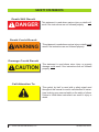
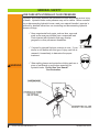
Versi Pro 07 (GVP 07)
SAFETY & OPERATOR’S MANUAL
CONTACT INFORMATION
World Headquarters
Genesis Attachments
Europe/Africa/Middle East
Genesis GmbH
1000 Genesis Drive
Superior, WI 54880 USA
Alpenstrasse 71
D-87700 Memmingen, Germany
Toll Free: 888-SHEAR-IT
(888-743-2748)
Phone: +49 83 31 9 25 98 0
Fax: +49 83 31 9 25 98 80
genesis-europe.com
Phone: 715.395.5252
Fax: 715.395.5255
E-mail:
[email protected]
E-mail:
[email protected]
Asia Pacific Representative Office
24 Upper Serangoon View #12-28
Singapore 534205
Phone: +65 9673 9730
E-mail:
[email protected]
Central & South America, The Caribbean
Cra 13A #89-38 / Ofi 613
Bogota, Colombia
Phone: (57-1) 610-8160 / 795-8747
E-mail:
[email protected]
Brazil
Rua José Alves dos Santos, 281 - Sala - 413
São José dos Campos / SP - Brazil
Phone: +55 (12) 3905-3405
E-mail:
[email protected]
View and download all manuals at genesisattachments.com/manuals.asp
2
© 2015 Genesis Attachments, LLC
Genesis Versi Pro 07
PREFACE
To ensure years of safe, dependable service, only trained and authorized persons should operate
and service your Genesis attachment. It is the responsibility of the operator to read, fully understand and follow all operational and safety-related instructions in this manual. Do not operate the
attachment until you have read and fully understand these instructions. Always use good safety
practices to protect yourself and those around you.
REGISTRATION FORM
The Warranty Registration Form must be filled out by the dealer or customer and returned to Genesis
indicating the date the machine went into service.
IMPORTANT
This operator’s manual must remain with the attachment at all times.
MANUAL REPLACEMENT
Should this manual become damaged or lost, immediately contact any authorized Genesis dealer or
the Genesis Service Department at 888-743-2748 or 715-395-5252 for a replacement.
POSSIBLE VARIATIONS
Genesis has made every effort to provide information as complete and accurate as possible for its
attachments. However, because of owner requirements, equipment and control, variations may
exist. In addition, due to Genesis’ policy of continually striving to improve its products, occasional
discrepancies may exist between individual attachments and the descriptions and information
contained herein.
PUBLIC NOTICE
Genesis reserves the right to make changes and improvements to its products at any time without
public notice or obligation. Genesis also reserves the right to discontinue manufacturing any product
at its discretion at any time.
WARRANTY
All work or repairs to be considered for warranty reimbursement must be pre-authorized by the
Genesis Service Department. Any alterations, modifications or repairs performed before authorization by the Genesis Service Department will render all warranty reimbursement consideration null
and void without exception. See page 48 for Warranty Claim Procedures.
A lack of, or improperly performed, maintenance and procedures as set forth in this manual as well
as operator abuse may render warranty consideration null and void.
© 2015 Genesis Attachments, LLC
Genesis Versi Pro 07
3
4
© 2015 Genesis Attachments, LLC
Genesis Versi Pro 07
TABLE OF CONTENTS
SAFETY STATEMENTS
GENERAL SAFETY
Read Manual Before Installation
Read and Understand All Safety Statements
Know Your Equipment
Lower or Support Raised Equipment
Do Not Modify Machine or Attachment
Protect Against Flying Debris
GENERAL SAFETY
Use Care with Hydraulic Fluid Pressure
GENERAL SAFETY
Safely Maintain and Repair Equipment
Maintaining the Attachment
GENERAL SAFETY
Safely Operate Equipment
GENERAL SAFETY
Safely Operate Equipment
Know Where Utilities Are
Operator Qualifications
Unsafe Conditions
Emergency Situations
GENERAL SAFETY
Personal Safety
Before Operating
Know the Work Area
GENERAL SAFETY
Machine Stability
Check the Equipment
Position the Attachment
GENERAL SAFETY
Operation Safety
Know the Rules
Lighting
Lockout / Tagout
Process Material Safely
Hydraulic Settings
© 2015 Genesis Attachments, LLC
10
11
12
13
14
15
16
17
18
Genesis Versi Pro 07
5
TABLE OF CONTENTS
GENERAL SAFETY
Fire Hazards
Stability
Place the Load Safely
Fastener Identification
Starting Procedure
To Start
To Shut Down
GENERAL SAFETY
High Voltage Lines May Arc
Power Lines
Working Overhead
Prioritized Oil Flow
MAINTENANCE SAFETY
Trained and Authorized
Repairs
Authorized Parts
Schedules
Torque Specs
Welding
Maintenance
Equipment Conditions
MAINTENANCE SAFETY
Pressurized System
Medical Assistance
Burns
Ventilate the Area
Sanding / Grinding
Prevent Fires
Proper Bolts
MAINTENANCE SAFETY
Performing Maintenance
Unsafe Condition
Equipment Condition
Maintenance Schedule
Eight Hour Checklist
Inspect
Grease
Long-Term Maintenance
6
© 2015 Genesis Attachments, LLC
19
20
21
22
23
Genesis Versi Pro 07
TABLE OF CONTENTS
MAINTENANCE
Bolt Torque Specifications
HYDRAULIC / ROTATION MAINTENANCE
Mounting Bolts
Bolt Torque
Grease Slewing Ring
Rotate After Greasing
Yoke Greasing
Grease Temperatures
MAINTENANCE - GREASE
ATTACHMENT MARKINGS
INSTALLATION
Attachment Installation
Electric Installation
Versi-Pro Standard Eight-Pin Connection
Hydraulic Installation
INSTALLATION
Hydraulic Start-Up
Start-Up Procedure
OPERATION
General Operation Instructions
Start Up
Efficient and Productive Operation
OPERATION
Common Operational Concerns
OPERATION
Jaw Set Change-Over
Jaw Removal
Jaw Installation
JAW SET MAINTENANCE
Pivot Group Adjustment GVP07 Rev A
SHEAR JAW SET MAINTENANCE
Piercing Tip
Piercing Tip Replacement
SHEAR JAW SET MAINTENANCE
Wear Plate Replacement
SHEAR JAW SET MAINTENANCE
Guide Blades
Guide Blade Shimming
© 2015 Genesis Attachments, LLC
24
25
26
27
28
29
30
31
32
33
34
35
36
Genesis Versi Pro 07
7
TABLE OF CONTENTS
SHEAR JAW SET MAINTENANCE
Guide Blade Rotation
Guide Blade Replacement
Cutting Edges
Blade Removal
Blade Bolts
SHEAR JAW SET MAINTENANCE
Blade Rotation
CONCRETE CRACKER JAW SET MAINTENANCE
Tooth Replacement Procedure
WIRE CUTTER JAW SET MAINTENANCE
Wire Cutter Jaw Removal
Wire Cutter Jaw Installation
GRAPPLE JAW SET MAINTENANCE
Tip Replacement Procedure
WELDING MAINTENANCE
General Welding Guidelines
Welding Ground Clamp
Welding Rules
Before you begin
During welding
After welding maintenance is complete
WELDING MAINTENANCE
Build-Up
WELDING MAINTENANCE
Hard-surfacing
WELDING MAINTENANCE
Hard-surfacing Patterns
HYDRAULIC / ROTATION MAINTENANCE
Hydraulic Requirements
Electrical Requirements
TROUBLE-SHOOTING GUIDE
Jaw Set Trouble-Shooting
TROUBLE-SHOOTING GUIDE
Rotator Trouble-Shooting
WARRANTY CLAIM PROCEDURE
PARTS ORDER POLICY AND PROCEDURE
PARTS ORDER FORM
GLOSSARY
INDEX
8
© 2015 Genesis Attachments, LLC
37
38
39
40-45
46
47
48
49
50
51
52
53
54
55
56
57-58
59-61
Genesis Versi Pro 07
NOTES
© 2015 Genesis Attachments, LLC
Genesis Versi Pro 07
9
SAFETY STATEMENTS
Death Will Result
! DANGER
This statement is used where serious injury or death will
result if the instructions are not followed properly.
Death Could Result
! WARNING
Damage Could Result
! CAUTION
This statement is used where serious injury or death could
result if the instructions are not followed properly.
This statement is used where minor injury or property
damage could result if the instructions are not followed
properly.
Call Attention To
This symbol by itself or used with a safety signal word
throughout this manual is used to call attention to instructions involving your personal safety or the safety of others.
Failure to follow these instructions can result in injury or
death.
10 © 2015 Genesis Attachments, LLC
Genesis Versi Pro 07
GENERAL SAFETY
READ MANUAL BEFORE INSTALLATION
Read this manual before attempting to operate the attachment.
This operator’s manual should be regarded as part of the attachment. For proper installation, operation or maintenance, operators and maintenance personnel should read this manual along
with the manuals of the material handler or serious injury or
death could result.
READ AND UNDERSTAND ALL SAFETY STATEMENTS
Read all safety statements in this manual prior to operating or working on this
attachment. Know and obey all OSHA regulations, local laws and other professional guidelines for your operation. Know and follow good work practices
when assembling, maintaining, repairing, mounting, removing or operating this
attachment.
KNOW YOUR EQUIPMENT
Know your attachment’s capabilities, dimensions and
operations before operating. Visually inspect your
attachment before you start and never operate an
attachment that is not in proper working order with
all safety devices in place. Remove and replace any
damaged or excessively worn parts.
LOWER OR SUPPORT RAISED EQUIPMENT
Do not work under raised booms without supporting them. Do not use support
material made of concrete blocks, logs, buckets, barrels, or any other material
that could suddenly collapse or shift positions. Make sure support material is
solid, not decayed, warped, twisted or tapered. Lower boom and attachment to
the ground before leaving the cab or operator’s station.
DO NOT MODIFY MACHINE OR ATTACHMENT
Modifications may weaken an attachment’s integrity and impair its function, life
and performance. When making repairs, use only the manufacturer’s genuine
parts, following authorized instructions. Other parts may be substandard in fit
and quality. Never modify any ROPS (Roll Over Protection Structure) or FOPS
(Falling Object Protective Structure) equipment or device. Any modifications
must be authorized in writing by the manufacturer.
PROTECT AGAINST FLYING DEBRIS
Always wear proper safety glasses or a face shield
when driving pins in or out, or when an operation causes dust,
flying debris or any other hazardous material.
© 2015 Genesis Attachments, LLC
Genesis Versi Pro 07
11
GENERAL SAFETY
USE CARE WITH HYDRAULIC FLUID PRESSURE
Hydraulic fluid under pressure can penetrate the skin and cause serious injury
or death. Hydraulic leaks under pressure may not be visible. Before connecting or disconnecting hydraulic hoses, read your material handler’s operator’s
manual for detailed instructions on connecting and disconnecting hydraulic
hoses or fittings.
!
P Keep unprotected body parts, such as face, eyes and
P If injured by injected fluid see a doctor at once. If your
arms as far away as possible from a suspected leak.
Flesh injected with hydraulic fluid may develop
gangrene or other permanent disabilities.
doctor is not familiar with this type of injury, ask him to
research it immediately to determine the proper
treatment.
P Wear safety glasses and protective clothing and use a
piece of cardboard or wood when searching for
WARNING hydraulic leaks. Do Not Use Your Hands!
See Illustration.
12 © 2015 Genesis Attachments, LLC
Genesis Versi Pro 07
GENERAL SAFETY
SAFELY MAINTAIN AND REPAIR EQUIPMENT
P Do not wear loose clothing or any accessories that
can catch in moving parts. If you have long hair, cover
or secure it so it does not become entangled in the
equipment.
P Work on a level surface in a well lit area.
P Use properly grounded electrical outlets and tools.
P Use the correct tool for the job. Make sure
P Wear protective equipment specified by the tool
it is in good condition for the task required.
manufacturer.
MAINTAINING THE ATTACHMENT
P Before performing maintenance, lower the attachment
P Never perform any work on the attachment unless you
P Never make hydraulic repairs while the system is under
to the ground, turn off the engine, remove the key and
apply the brakes. Perform appropriate Lockout / Tagout
procedures.
are authorized and qualified to do so. Always read the
operator’s service manuals before making any repair.
After completing maintenance or repair, check for
correct functioning of the attachment. If not functioning
properly, always tag “DO NOT OPERATE” until all
problems are corrected.
pressure. Serious personal injury or death could result.
© 2015 Genesis Attachments, LLC
Genesis Versi Pro 07
13
GENERAL SAFETY
SAFELY OPERATE EQUIPMENT
Do not operate equipment until you are completely trained by a qualified operator in how to use the controls and know its capabilities, dimensions and all
safety requirements.
See your machine’s manual for these instructions.
P Operate only from the operator’s seat. Check the seat belt
P An operator must not be under the influence of drugs or
P Never leave equipment unattended with the engine running or with
daily and replace if frayed or damaged.
alcohol, which can change their alertness or
coordination. An operator taking prescription or
over-the-counter drugs should seek medical advice on
whether or not they can safely operate equipment.
the attachment in a raised position.
P Before exiting the prime mover, lower the attachment to the ground,
turn off the prime mover’s engine, remove the key and apply the
brakes.
P Do not exceed the lifting capacity of your prime mover.
P When operating on slopes, drive up and down, not
P Reduce speed when driving over rough terrain or on a
across. Avoid steep hillside operation, which could
cause the prime mover to overturn.
slope, or when turning, to avoid overturning the vehicle.
P Never heap-load heavy material where the combined weight of the
bucket and material could exceed the rated lifting capacity of the
loader.
P Never use the attachment for a work platform or personnel carrier.
P Keep all step plates, grab bars, pedals and controls free of dirt,
P Never allow anyone to be around the equipment when it is operating.
grease, debris and oil.
P Do not allow riders on the attachment or the prime
mover.
14 © 2015 Genesis Attachments, LLC
Genesis Versi Pro 07
GENERAL SAFETY
SAFELY OPERATE EQUIPMENT
P Do not alter or remove any safety feature from the
prime mover or this attachment.
P Know your work site safety rules as well as traffic rules
P A heavy load can cause instability of the prime mover.
and flow. When in doubt on any safety issue, contact
your supervisor or safety coordinator for an explanation.
Use extreme care during travel. Slow down on turns
and watch out for bumps. The prime mover may need
additional counter-weights to counter-balance the
weight of the attachment.
KNOW WHERE UTILITIES ARE
Observe overhead electrical and other utility lines. Be sure equipment will clear
them. When digging, call your local utilities for the location of buried utility lines,
gas, water and sewer lines, as well as any other hazards.
OPERATOR QUALIFICATIONS
Only trained and authorized persons should operate this machine
and attachment. To be qualified, you must understand the written
instructions in this manual and know all safety rules and
regulations of the job site.
Do not operate the machine until you fully understand the function
of all controls, indicators and instruments.
UNSAFE CONDITIONS
Do not operate if an unsafe condition exists. Stop operation immediately, shut
down the machine and report the unsafe condition to the proper authority.
Equipment operation and maintenance practices directly affect your safety and
the safety of those around you. Always use common sense while operating and
be alert to unsafe conditions.
EMERGENCY SITUATIONS
Always know where to get assistance in case of an emergency.
Know where to locate and how to use safety equipment such as a
first aid kit and fire extinguisher.
Report all injuries to your supervisor or as directed.
© 2015 Genesis Attachments, LLC
Genesis Versi Pro 07
15
GENERAL SAFETY
PERSONAL SAFETY
Use all protective clothing and safety devices dictated by the working conditions.
These may include but are not limited to:
P Hard hat
P Safety glasses, goggles or face shield
P Hearing protection
P Safety shoes
P Heavy gloves
P Reflective clothing
P Respirator or filter mask
BEFORE OPERATING
Warn all others in the area that you are about to start operation.
Perform the “Check the Equipment” (Page 17) steps outlined in this manual.
Check underneath and around the machine. Make sure all personnel and equipment are clear from the area of operation and equipment movement. Check
clearances in all directions, including overhead.
Be properly seated in the operator’s seat.
Do not attempt to operate the controls until you have read and fully understand
the safety statements in this manual and the OEM manual for your carrier (skid
steer or mini-excavator). Determine the control for each function before operating the carrier.
Familiarize yourself with the carrier and attachment before attempting to process
material. Have the carrier moved to a wide open area. The area should be solid,
level and free of obstacles such as people, equipment, buildings and power lines.
With the carrier engine running at a reduced speed, operate one control at a
time. Continue this practice until you have learned and become comfortable with
the function of each control.
KNOW THE WORK AREA
Check clearances in the work area. Keep all bystanders at a safe distance. Do
not work under obstacles within the working range of your Genesis attachment.
Check the location for overhead and buried power lines or other utilities before
operation.
Check ground conditions. Be aware of and avoid unstable or slippery areas.
16 © 2015 Genesis Attachments, LLC
Genesis Versi Pro 07
GENERAL SAFETY
MACHINE STABILITY
Your Genesis attachment is sized for carrier stability when properly operated.
However, improper operation, faulty maintenance or unauthorized modifications
may cause instability.
P Know the working ranges and capacities of the
carrier to avoid tipping.
P Use the recommended carrier counter weight.
The following conditions affect stability:
P Ground conditions
P Grade
P Weight of attachment
P Contents of attachment
P Operator judgement
CHECK THE EQUIPMENT
Before beginning each shift, take the time to check the equipment and have all
systems in good operating condition.
Check the following:
P Warning decals, special instructions and owner’s manual. Make sure they are legible and in the proper location.
P Grease fittings. Pump grease at all fitting locations. (See Page 26)
P Hydraulic fluid level. Add hydraulic fluid as required.
P Hydraulic hoses and hose connections for wear or leaks. Repair or replace any damaged hoses or connections.
P All control levers for proper operation.
P Rotation bearing. Visually check for loose or
damaged bolts. If repair is required, refer to
qualified personnel.
GOOD
P Grease rotation bearing and pinion gear.
CONDITION
P Check for loose or missing pin retaining bolts.
P
POSITION THE ATTACHMENT
Position the carrier on firm level ground. Do not operate on slippery ground
conditions.
If level ground is not possible, position the carrier to use the attachment to the
front or back of the carrier. Avoid working over the side of the carrier.
To reduce the risk of tipping and slipping, never park on a grade exceeding 10%
(one-foot rise over the span of a ten-foot run).
© 2015 Genesis Attachments, LLC
Genesis Versi Pro 07
17
GENERAL SAFETY
OPERATION SAFETY
Safe operation is the responsibility of the operator. Improper use of the machine
can lead to dangerous situations for yourself, those around you, the machine
and the work area. Practice safe working habits and be aware of hazardous
conditions.
KNOW THE RULES
Most employers have rules governing proper operation and maintenance of
equipment. Before starting work at a new location, ask your supervisor or safety
coordinator about rules you are expected to obey.
LIGHTING
Do not operate without lights if conditions require them. If lights are required
and your machine is not so equipped, contact your carrier dealer for a lighting
package.
LOCKOUT / TAGOUT
Rotation systems are designed to position the
attachment during operation, not as a locking or
supporting system during maintenance. Always
use proper blocking procedures during maintenance for operator safety. Always practice
lockout/tagout procedures before performing
maintenance.
PROCESS MATERIAL SAFELY
Using your Genesis Versi Pro in unauthorized applications may create an unsafe
situation and will void the warranty.
Do not pull down structures with your Genesis Versi Pro. Doing so may cause
falling debris, or material may break free and exceed the capacities of the carrier,
causing a tipping hazard.
The rotator should only be used for positioning your Genesis attachment. Do not
use the rotator to pry or break loose material.
HYDRAULIC SETTINGS
The hydraulic system has been preset and tested by your dealer.
Do not alter hydraulic settings without consulting an authorized
Genesis dealer or Genesis’ Service Department. Doing so will
void the warranty and may cause structural damage, accidents
or tipping.
18 © 2015 Genesis Attachments, LLC
Genesis Versi Pro 07
GENERAL SAFETY
FIRE HAZARDS
Avoid fire hazards. Keep the area clean. Remove all flammable
materials from the area during any welding or heating process.
Have a fire extinguisher nearby and know how to use it.
STABILITY
For greater stability, knuckle the attachment to bring the load closer to the center
of rotation (center of gravity) while lifting. Use extra caution during reaching to
avoid tipping.
PLACE THE LOAD SAFELY
Do not move the attachment, or anything held in the jaws, over people, equipment
or buildings. Do not throw or drop the contents. Operate the controls smoothly
and gradually. Jerky controls are hazardous and may damage the carrier.
FASTENER IDENTIFICATION
Never substitute pins or bolts. Use factory supplied pins. Replace
all bolts with the same size and grade. Failure to do so may cause
serious injury or death.
STARTING PROCEDURE
Before operating, walk completely around the equipment to make certain no one
is under, on or close to it. Keep all bystanders at least 75 feet away from the area
of operation and equipment movement. Let all other workers and bystanders
know you are preparing to start. DO NOT operate until everyone is clear.
Always be properly seated in the operator’s seat before operating any carrier
controls.
To start:
P Make sure all controls are in the center (neutral) position.
P Be properly seated.
P Slowly operate all functions to check for proper operation
and to bleed air from the hydraulic system.
To shut down:
P Return your Genesis attachment to a rest position on the ground.
P Shut off the carrier engine.
P Work controls in all directions to relieve hydraulic pressure.
© 2015 Genesis Attachments, LLC
Genesis Versi Pro 07
19
GENERAL SAFETY
HIGH VOLTAGE LINES MAY ARC
Current in high voltage lines may arc some distance from the
wire to a nearby ground. Keep all parts of the machine at least
50 feet (16m) away from power lines.
POWER LINES
! DANGER
Do not operate the machine near energized power lines. All
local, state/provincial and federal regulations must be met before
approaching power lines, overhead or underground cables, or
power sources with any part of the excavator or skid steer. Always
contact the electrical power company when operating near power
lines. The lines should be moved, insulated, disconnected or
de-energized and grounded before operating in the area.
IF LOOSE BOLTS ARE FOUND, DO NOT OPERATE THE ATTACHMENT.
CONTACT THE FACTORY.
STAND CLEAR WHEN THE ATTACHMENT IS BEING ROTATED. ALWAYS
STAY IN CLEAR VIEW OF THE OPERATOR.
WORKING OVERHEAD
! WARNING
Avoid handling material overhead whenever possible. Safety
glass and wire mesh cab guarding must be installed to protect the
operator from flying debris that may be created during handling.
Falling Object Protection Structures, or FOPS, are necessary for
any application where material is to be handled overhead.
PRIORITIZED OIL FLOW
Material handlers in overhead operations or high reach conditions must have
prioritized oil flow to their main valves.
20 © 2015 Genesis Attachments, LLC
Genesis Versi Pro 07
MAINTENANCE SAFETY
TRAINED AND AUTHORIZED
Only trained and authorized persons should perform maintenance on the Versi
Pro. To be qualified, you must understand the instructions in this manual, have
training, and know the safety rules and regulations of the job site.
REPAIRS
Do not attempt repairs you do not understand. If any questions arise regarding a safety or maintenance procedure,
contact Genesis or your Genesis dealer.
AUTHORIZED PARTS
Use factory authorized parts. The use of unauthorized parts may compromise
safety, performance and durability of the attachment and may void the warranty.
SCHEDULES
Follow the daily checklist and maintenance schedules in this manual. Extreme
conditions may dictate shorter maintenance intervals.
TORQUE SPECS
Do not exceed bolt torque specifications. (See Page 24)
WELDING
Do not weld on structural components without consulting Genesis. Doing so may
cause structural failure and void the warranty.
MAINTENANCE
Do not work on the attachment before ensuring it will not move. Completely lower
the boom to the ground or in a rest position and relieve hydraulic pressure.
EQUIPMENT CONDITION
Never operate poorly maintained equipment. When maintenance is required,
repair or replace parts immediately.
© 2015 Genesis Attachments, LLC
Genesis Versi Pro 07
21
MAINTENANCE SAFETY
PRESSURIZED SYSTEM
Do not work on any hydraulic lines or components while they are pressurized.
Escaping hydraulic fluid can penetrate the skin, causing serious injury or death.
Relieve pressure before performing maintenance. Keep hands and body parts
away from pin holes and nozzles, which eject fluids under high pressure. Use a
piece of cardboard to search for leaks.
MEDICAL ASSISTANCE
If fluid is injected into the skin, seek medical assistance immediately from a doctor
familiar with this type of injury.
BURNS
Hydraulic oil becomes hot during operation. Do not let hydraulic oil or components contact skin, as it could cause severe burns. Allow hydraulic components
to cool before working on them. Use protective clothing and safety equipment.
If burned, seek immediate medical attention.
VENTILATE THE AREA
! WARNING
Remove paint before welding or heating. Hazardous fumes/dust can be generated when paint is heated by welding, soldering or using a torch. Do all work
outside or in a well ventilated area and dispose of paint and solvent properly.
SANDING / GRINDING
When sanding or grinding paint, avoid breathing the dust. Wear an approved respirator. If you use solvent or paint stripper, remove stripper with soap and water
before welding. Remove solvent or paint stripper containers and other flammable
materials from area. Allow fumes to disperse at least 15 minutes before welding
or heating.
PREVENT FIRES
Avoid fire hazards. Keep the area clean. Remove all flammable materials from
the area during any welding or heating process. Have a fire extinguisher nearby
and know how to use it.
PROPER BOLTS
Never substitute pins or bolts. Use factory supplied pins. Replace all bolts with
the same size and grade. Failure to do so may cause serious injury or death.
22 © 2015 Genesis Attachments, LLC
Genesis Versi Pro 07
MAINTENANCE SAFETY
PERFORMING MAINTENANCE
If maintenance or service is to be performed on your Genesis attachment, make
sure it is properly blocked to prevent accidental rotation of the attachment onto
the operator or mechanic. Do not rely on the rotation motor or other rotation components to inhibit movement of the attachment during maintenance or servicing.
Always perform appropriate Lockout / Tagout procedures.
UNSAFE CONDITION
Do not operate under unsafe conditions. If an unsafe condition arises during
operation, immediately shut down the equipment and report the situation to the
proper authority.
EQUIPMENT CONDITION
Do not operate poorly maintained or otherwise faulty equipment. Inform the
proper authority and DO NOT resume operation until the problem has been fixed.
! WARNING
MAINTENANCE SCHEDULE
Performing scheduled maintenance will promote safe, reliable operation of your
Versi-Pro. Use maintenance procedures described in this manual. If you are
not able to safely and competently perform these procedures, have a Genesis
dealer perform them.
Extreme operating conditions may require shortened maintenance intervals.
INSPECT
q
q
q
q
Eight-Hour Checklist
Bolts - Check for loose bolts, replace if damaged
Fittings and hoses for damage or leaks
Cylinders for damage or leaks
Hydraulic swivel for damage or leaks
GREASE
q
q
q
Slewing Ring and Drive Gear
Long-Term Maintenance
Check all bolts for loose washers, including slewing ring bolts, after
the first 80 hours of operation
Reseal cylinder every 2000 hours
© 2015 Genesis Attachments, LLC
Genesis Versi Pro 07
23
MAINTENANCE
BOLT TORQUE SPECIFICATIONS
P Genesis typically uses dry torque measurements.
P Prior to using the chart below, clean all bolt holes, bolts and nuts to remove
dirt, grease and oil. See the Visual Reference below or Parts Manual to
identify bolt type.
P Never re-torque bolts that use Loctite. If a bolt becomes loose or damaged,
after the initial use when Loctie was applied and the bolt was torqued,
the bolt must be replaced.
P Never break tightened bolts loose with a torque wrench. Doing so may break
the torque wrench or take it out of calibration.
P Torque wrenches should be calibrated on an annual basis.
P When using a torque multiplier with a torque wrench, incorrect settings will be
multiplied by the ratio of the torque wrench.
P Never use an air wrench on a torque multiplier.
Dry Torque Values
Fastener Grade
CL 10.9
8
Size x Pitch
Wet Torque Values
Nm
Ft-lb
M8 x 1.25
36.5
27
M10 x 1.50
72
53
M12 x 1.75
125
M14 x 1.50
Fastener Grade
Size x Pitch
Nm
Ft-lb
M20 x 2.50
458
338
M27 x 3.00
1157
850
92
M30 x 3.50
1572
1160
210
154
3/4-10
383
282
M14 x 2.00
200
148
7/8-9
617
455
M16 x 2.00
313
230
1.00-8
916
675
M20 x 1.50
640
472
1.25-7
1847
1362
M20 x 2.50
610
450
1.50-12
4067
3000
M24 x 3.00
1055
778
M27 x 3.00
1543
1138
M30 x 3.50
2095
1545
1/2-13
145
107
1/2-20
163
120
5/8-11
286
211
3/4-10
510
376
7/8-9
822
606
1.00-8
1220
900
1.00-14
1345
992
1.50-6
4280
3160
L9
1.00-8
1152
850
9
1.25-7
2464
1817
24 © 2015 Genesis Attachments, LLC
CL 10.9
8
9
Apply grease or anti-seize on threads and under bolt heads
Visual Reference
Genesis Versi Pro 07
HYDRAULIC / ROTATION MAINTENANCE
MOUNTING BOLTS
Visually check slewing ring (rotation bearing) bolts every eight hours of operation
and replace every 2000 hours. Do not reuse or re-torque these bolts. Immediately
replace a loose or broken bolt, and replace the bolts on either side of it. Apply
Loctite to the bolt threads and under the bolt head per Loctite instructions.
BOLT TORQUE
The bolts that secure the slewing ring are critical to safe operation of the attachment. Improper bolt torques may cause the bolts to fail and allow the attachment
to break free. This may result in serious personal injury and damage to equipment. Improper torques will also cause uneven wear on the slewing ring. See
Page 24 for proper bolt torque specifications.
GREASE DAILY
Rotating components must be greased daily. The rotation bearing features a
remote grease fitting at the top of the quick-attach plate. The gear teeth should
also be greased and can be accessed by removing the bearing shroud.
STAND CLEAR
Stand clear when the Versi Pro is being rotated. Always stay in clear view of the
operator.
ROTATE AFTER GREASING
Grease each slewing ring grease fitting with several strokes and rotate the
attachment two full rotations after greasing each fitting.
GREASE TEMPERATURES
For normal conditions above 32˚F (0˚C), use a lithium-based, premium
grade 2 extreme pressure grease. For temperatures below 32˚F, a grade 0
grease is recommended.
© 2015 Genesis Attachments, LLC
Genesis Versi Pro 07
25
MAINTENANCE
GREASE
! DANGER
SHUT OFF EXCAVATOR OR SKID STEER AND DISABLE HYDRAULICS
PER OEM INSTRUCTIONS BEFORE GREASING.
Use a lithium-based premium EP #2 in normal conditions above 32° F (0° C). Use Grade 0 in
temperatures below freezing.
Grease all fittings every eight hours of operation. Grease until extrusion is visible. Grease at the
end of the shift, when the attachment is warm.
After greasing the rotation bearing, rotate the Versi Pro through two full rotations.
Grease locations:
1. Front cylinder pin
2. Rear cylinder pin
3. Pivot group
4. Remote grease fitting for rotation bearing
5. Gear teeth inside bearing shroud
2
1
4
5
3
26 © 2015 Genesis Attachments, LLC
Genesis Versi Pro 07
ATTACHMENT MARKINGS
Decals are necessary for safe operation and maintenance. To reorder, contact your Genesis
dealer or call 715-395-5252.
Versi Pro 07 Markings
Model Number
Serial Number
(weld-on)
Logo
Viewing Distance
© 2015 Genesis Attachments, LLC
Genesis Versi Pro 07
27
INSTALLATION
ATTACHMENT INSTALLATION
Install the Versi Pro according to your carrier (skid steer or mini-excavator) OEM’s standard bucket/
attachment installation instructions.
ELECTRIC INSTALLATION
(For Electric Over Hydraulic Option)
Electric Over Hydraulic Option
OEM electrical
connector
The Versi Pro 07 requires an electrical connection to the
carrier (skid steer or mini-excavator). Carrier OEMs often
provide an electrical connector near the hydraulic quickcouplers. Genesis provides a wiring harness to connect
the Versi Pro to the carrier.
Genesis
wiring
harness
OR:
In the absence of an OEM-provided electrical connection,
Genesis provides a complete control system including joystick handles available for purchase.
Control system
(Joystick with buttons)
Versi Pro standard
eight-pin electrical
connector
Versi Pro Standard Eight-Pin Connection
A
B
C
D
E
F
G
H
Jaw open
Jaw close
Rotate clockwise
Rotate counter-clockwise
Regen override
Keyed power
Unloader
Ground
HYDRAULIC INSTALLATION
(For Fully Hydraulic Option)
Fully Hydraulic Option
OEM auxiliary
lines
The Versi Pro 07 is equipped with bulkhead connector
fittings to enable the installation of hydraulic lines to supply
hydraulic fluid to the shear jaw and rotation circuits.
Note: This option will require that the machine is equipped
with two (2) bi-directional flow hydraulic circuits equipped
with port reliefs and anti-cavitation valves.
28 © 2015 Genesis Attachments, LLC
Hydraulic
connections
Control system
inside cab
No electrical
connection
Genesis Versi Pro 07
INSTALLATION
HYDRAULIC START-UP
The Genesis Versi Pro 07 Processor is designed to operate up to 3650 PSI. Due to these high
pressures, it is important that air is bled from the attachment cylinder after installation. Failure to
follow these procedures could result in cylinder seal damage and/or base machine hydraulic system
damage.
START-UP PROCEDURE:
P Check the base machine hydraulic reservoir for proper fluid level.
P Prior to hooking up the attachment, the base machine hydraulic oil should be warmed up
P Do not operate the attachment circuit during the warm-up period.
P After the base machine has reached normal operating temperature, set the engine to
P Attachment must be vertical to bleed air from the cylinder.
P Slowly fill the bore end of the attachment cylinder to partially close the jaws. Do not allow P Slowly fill the rod end of the attachment cylinder to open the jaws. Note: Do not fully P Stop and check the base machine hydraulic fluid level again to be sure there is still
P Cycle the jaws five or six strokes before increasing to full operating pressure.
per the OEM procedures for starting and warm-up in cold weather.
idle speed.
the tank to run low - have someone watch the oil level gauge.
extend or retract attachment cylinder with the first cycles. Use partial strokes
extending and retracting, slowly working to full strokes.
sufficient fluid. Fill the reservoir as needed. Note: Hydraulic fluid level should be checked
with the shear jaw open (cylinder retracted).
© 2015 Genesis Attachments, LLC
Genesis Versi Pro 07
29
OPERATION
GENERAL OPERATION INSTRUCTIONS
Follow all rules and procedures outlined in the Operation Safety
section under General Safety in this manual.
Use the attachment only as intended; in approved applications as set forth in this manual.
Do not allow attachment, exposed cylinder rod, or hoses to come into contact with any obstacles,
buildings or the excavator.
The attachment is not intended to crush or break objects or structures by swinging or dropping the
attachment.
START UP
INITIAL OPERATION & RESTART AFTER MAINTENANCE
During initial operation and any time jaw maintenance has been performed, process thin and lighter
material first to “work harden” wear areas, developing a harder, more durable edge. This is also the
most effective time to process materials such as sheet metal or wire. The new or repaired edges
will cut more efficiently and be less likely to get material jammed between the blades.
When operating in temperatures below freezing, it is also important to process light materials first.
This allows the jaw set’s structural material to “warm up,” preventing thermal cracking.
EFFICIENT AND PRODUCTIVE OPERATION
Operators should become accustomed to performing work in the most proficient manner possible.
PROBLEMS WITH DIRT
When cutting, build up and cut out of small piles, keeping the surfaces of the chin plate and upper
jaw out of the dirt as much as possible. Dirt is much more abrasive than steel and needlessly
increases build-up and hard-surfacing time and intervals.
ORGANIZE WORK AREA
It also helps to give yourself enough room to keep out of the way of other personnel and machines.
Material should be picked from a pile, swung to the side and cut in a new area. This prevents
redundant cutting of the same pieces and allows for the newly prepared material to be loaded out
with another material handling machine.
MATERIAL PROCESSING AREAS
Material processing areas should be as close as safely possible to the location for loading materials
for transportation. Less time spent processing, loading and transporting materials greatly affects
operational costs and productivity and dramatically reduces man hours, fuel costs and equipment
wear.
ASSESSING MATERIALS
Operators should develop the habit of assessing materials to be processed and visualizing a starting
and finishing point to use the fewest cuts possible. Excessive moving, positioning and handling cost
time and money. Bringing the jaws to full open, when only partial jaw open is needed for a cut,
wastes time and fuel, slows other excavator functions as well as causes needless wear to hydraulic
components, hoses and O-rings. More efficient processing will extend the attachment life.
30 © 2015 Genesis Attachments, LLC
Genesis Versi Pro 07
OPERATION
COMMON OPERATIONAL CONCERNS
SHEAR JAW STALLS
When cutting larger materials and the shear jaw stalls just before cutting, suspend the material
on the prepared pile, open the jaw and position the material as close to the throat as possible.
Without pushing down on the material with excavator or skid steer force, rapidly close the jaw on the
material. Using the speed of regeneration can improve performance when cutting larger materials.
CHATTER WHILE CUTTING - PIERCING TIPS & GUIDE BLADES
If the attachment starts to chatter while cutting, back out of the cut and reposition at a different spot.
Chattering is an indication that material is jamming between the piercing tips and guide blades
or between upper and lower cutting blades. This indicates that blade maintenance needs to be
performed immediately. Worn blades and improper blade gaps are usually the cause.
CHATTER WHILE CUTTING - THERMAL EXPANSION
Insufficient piercing tip gaps will also cause this, as the blades and parent material of the jaws are
subject to thermal expansion from cutting friction. The tighter the blades run, the hotter they get and
the more they expand. Piercing tips and guide blades are the most susceptible to this and will show
blue streaking on their corresponding faces. In some cases, they will get so hot that surface cracks
and spidering occur. As this happens, it will spread the lower jaw and increase gaps between the
primary and secondary blades, causing thin material to jam between them.
CHATTER WHILE CUTTING - WEDGED MATERIAL
Another key area to watch is the opening between the guide blades. Be aware of material that may
get into this opening before the piercing tip moves into this space, as it will be wedged between the
piercing tip and guide blades.
JAMMING CONDITIONS
Most jamming conditions can be prevented if the operator pays attention to the sound and vibration
that is associated with a jam. Remember that because of the rod-to-bore ratios of displacement on
the attachment’s hydraulic cylinder piston, the shear has half the force on jaw open compared to
jaw close. Therefore, it will not have enough cylinder force to open if material gets jammed into the
cutting blade area. Please contact the Genesis Service Department for advice on removing jammed
material.
© 2015 Genesis Attachments, LLC
Genesis Versi Pro 07
31
OPERATION
JAW SET CHANGE-OVER
Pin Head
Retaining Bolts
Front Cylinder
Pin
JAW REMOVAL
It is safer, easier and quicker to change the jaw sets with two
people; one person to remove the attaching pins and the other to
operate the machine.
Position the Versi Pro with the lower side of the stick toward the
ground. Set the tool firmly onto flat, level ground.
Fully close the attachment jaw. Remove the pin head retaining bolts
from both the front cylinder pin and the jaw connection pin. (Fig. 1)
Remove the front cylinder pin. Slowly retract the cylinder rod (jaw
open function). If the upper jaw moves, stop and pry the cylinder
clevis away from the upper jaw.
Jaw Connection Pin
Fig. 1
CLOSE JAWS BEFORE ROTATING
! WARNING
Close the jaws before rotating the Versi Pro back to the vertical position. Failure to do so
will allow the jaw to slam shut which may cause serious injury or damage to the machine.
Remove the jaw connection pin. This can also be done by raising
the attachment and carefully rotating the stick so the jaw connection
pin head is facing downward, then tapping the pin out.
With the pins removed and the attachment stick returned to a position with the lower side of the stick facing the ground, raise the stick
up and tilt the jaw toward the ground until the lower jaw attachment
pins clear the stick body attachment hooks; the stick will be tilted
about 30° or more when the jaws disconnect from the stick. (Fig. 2)
JAW INSTALLATION
Lower Jaw
Attachment Pins
The jaw set to be installed should be placed on firm level ground
with the cylinder connection facing upward.
Attaching
Hooks
Tilt the shear stick into a 30° position to connect the stick body
attachment hooks onto the lower jaw attachment pins. Once they
are connected, tilt the shear stick back into a horizontal position
making sure the attaching pins are firmly inside the attaching hooks.
(Fig. 2)
Install the jaw connection pin and its retaining bolt. If the jaw had
been rotated to install the pin from the top, rotate it back so the
lower side of the stick is again facing the ground. (Fig. 1)
Extend the cylinder rod (jaw close function) until the cylinder connection aligns itself to the jaw connection. Install the front cylinder
pin and its retaining bolt. Slowly open and close the jaw, checking
for any interference.
Fig. 2
32 © 2015 Genesis Attachments, LLC
Genesis Versi Pro 07
JAW SET MAINTENANCE
PIVOT GROUP ADJUSTMENT GVP 07 REV A
Maintain proper pivot group adjustment to optimize cutting performance and maximize the life of the
jaw set. Use the following procedure, along with the accompanying drawing, for initial set-up and to
make adjustments as the bearings wear.
1. Loosely assemble pivot group without end caps.
2. Set blade gap by pushing upper jaw blades against lower jaw blades with a .010” shim between
them.
3. Ensure sleeve 1 is pressed tightly against upper jaw flange bearing 1. Measure the dimension D1
and install shims to eliminate this gap. Fasten end cap 1 to the shaft on this side.
4. Measure the dimension D2 and install appropriate shims.
5. Ensure end cap 1 is pressed tightly against the lower jaw and measure dimension D3. Subtract
D3 from .255” to determine the shim thickness required under the end cap. Use a 3/8” dowel pin
or a light film of grease to hold shims in place.
6. Tighten end cap 2. Verify a .005” clearance in the pivot group with a feeler gage between the
sleeve and the flange bearing on either side of the upper jaw.
7. Grease pivot group as described in this manual.
End cap 2
D2
Sleeve 2
↓
↑
Flange
bearing 2
Flange
bearing 1
Sleeve 1
D3
↓
↑
Upper jaw
↓
↑
Set blade gap at .010”
D1
Lower jaw
End cap 1
© 2015 Genesis Attachments, LLC
Genesis Versi Pro 07
33
SHEAR JAW SET MAINTENANCE
DAILY MAINTENANCE CHECKS
Perform the following daily maintenance checks to keep
the equipment in good operating condition.
Wear Plate
P Ensure proper pivot group adjustment.
P Check blades, guide block and piercing tip for excess wear. Rotate or replace as needed.
P Inspect jaw for wear, including the chin where the
piercing tip meets the lower jaw. Perform build-up
and hardsurfacing as needed.
Piercing
Tip
PIERCING TIP
Proper maintenance of the piercing tip boosts
productivity and prevents material jams. Inspect the
piercing tip daily for wear and perform maintenance
every 20-40 hours, depending on the application.
Slowly cycle the shear until the piercing tip is flush with
the top edge of the chin.
Check the gap with a tape measure. Acceptable gap is
1/4” – 3/8” (6 - 9.5 mm)
Check the condition of the piercing tip with a straight
edge or square. Check the profile along the blades.
If the piercing tip is only slightly worn, it can be built up
following the build-up and hard-surfacing procedure in
this manual. When the tip is severely worn, it must be
replaced.
PIERCING TIP REPLACEMENT
Important: Remove the upper secondary blade and
upper wear plate during this procedure to prevent
damage.
Preheat the tip area to 350° F (177° C), six to eight
inches around the tip. Maintain this temperature
throughout the procedure. Do not exceed 400° F
interpass temperature.
Air arc to remove the piercing tip. Clean the pocket and
chamfer the perimeter at ½” x 45° angles.
Check
gap
Position and tack the new piercing tip in place, square
with the blades and new wear plate.
34 © 2015 Genesis Attachments, LLC
Genesis Versi Pro 07
SHEAR JAW SET MAINTENANCE
Weld with AWS E7018 electrode. Begin with the
sides, filling in the chamfered area with single passes,
alternating sides and peening each pass. Weld the back
and front following the same method.
When welding is complete, grind the welds flush on each
side.
Cycle the jaw slowly to check for interference.
Cover with heat blanket and allow to cool slowly.
DO NOT put unit into operation until cool.
WEAR PLATE REPLACEMENT
Important: Remove the upper secondary blade during
this procedure to prevent interpass temperature.
Position and tack the new wear plate in place.
Weld with AWS E7018 electrode. Begin with the area
between the wear plate and piercing tip.
Fill in the area with single passes, peening each pass.
Weld the back and front following the same method.
When welding is complete, grind the welds flush with the
wear plate and piercing tip.
Cycle the jaw slowly to check for interference.
Cover with heat blanket and allow to cool slowly.
DO NOT put unit into operation until cool.
© 2015 Genesis Attachments, LLC
Genesis Versi Pro 07
35
SHEAR JAW SET MAINTENANCE
GUIDE BLADES
After performing piercing tip maintenance, check guide
blade tolerances. When necessary, shim the guide blade
to keep the gap within 0.005” - 0.010”.
Rotate the guide blades when worn to a 1/8” (3 mm)
radius. Replace the guide blade when more than .075”
(2 mm) of shims are required to keep the blade gap within
the tolerances.
Gap =.005”-.010”
Guide Blade Shimming
Slowly close the jaw so the upper piercing tip begins to
bypass the guide blades. Stop the jaw and check the gap
between the guide blades and piercing tip. Cycle the jaws
slowly, stopping at several points along the piercing tip to
check the gap each time.
Shim the guide blades as needed to keep the gap within a
0.005” - 0.010” tolerance.
To install shims, loosen blade bolts and slide shims
between the guide blade and guide blade seat. Re-torque
bolts and recheck the gap.
Guide Blade Seat
Guide Blade
36 © 2015 Genesis Attachments, LLC
Shims
Genesis Versi Pro 07
SHEAR JAW SET MAINTENANCE
GUIDE BLADE ROTATION
Remove the blade bolts, guide blade and shims. Rotate the blade end-for-end or side-to-side; reinstall and torque bolts. Check gap; shim if required.
If guide blade faces are worn excessively, the blades cannot be rotated to place the uneven surfaces against the mating surface of the guide blade seats. Uneven surfaces will not be supported
and will break, possibly resulting in damage to the guide blade seat.
Guide Blade Replacement
Remove guide blade and shims. Install new guide blade with no shims. Check blade gap and shim
as needed.
CUTTING EDGES
Proper maintenance of the cutting edges is required for optimal performance. Blade rotation extends
blade life. Dull blades make the carrier hydraulic system work harder and may cause structural
damage to the Versi Pro.
Rotate blades to use all four cutting edges. Always use Genesis-approved blades. Blades that do
not meet Genesis specifications can cause major problems, and using them may void the warranty.
Before performing any blade maintenance, read, fully understand and follow these safety rules.
Wear personal safety equipment including gloves, safety glasses, safety boots and proper clothing.
Never strike a blade with a hardened steel tool. The blade may fragment, creating sharp flying
objects.
BLADE REMOVAL
Loosen the bolts enough to loosen the blades, one blade at a time.
Carefully remove bolts and blades.
BLADE BOLTS
Visually check for loose or broken bolts daily. Re- torque loose bolts to the specifications listed in
the torque chart in this manual. Replace broken bolts immediately.
© 2015 Genesis Attachments, LLC
Genesis Versi Pro 07
37
SHEAR JAW SET MAINTENANCE
BLADE ROTATION
Inspect blades every eight hours of operation. Re-torque
loose bolts and replace broken bolts. Rotate blades when
the cutting edges are worn to a 1/8” (3 mm) radius.
Recommended rotation intervals are approximately 20-80
hours, depending on the material being processed. Thin
materials may require shorter rotation intervals. Blades
must be replaced when all four edges are worn to an 1/8”
(3 mm) radius.
The following chart may be copied and used to track blade
rotation.
40-80 Hours
Date
Hour Meter
Original Blade Configuration
First Rotation
Rotate both blades end-for-end
Performed By
Installed
Rotation 1
Second Rotation
Rotate both blades front-to-back and
exchange seat positions
Rotation 2
Rotation 3
BLADE GAP ADJUSTMENT & SHIMMING
After each blade rotation, shim the lower blades to keep the
gap within .005 to .010. Do not shim the upper blades. Use
only Genesis shim kits.
Third Rotation
Rotate both blades end-for-end
Slowly close jaws until blades begin to bypass. Stop the
jaw and check the gap with a feeler gauge.
Cycle the jaws slowly and continue checking the gap at
several points along the entire length of the blades.
If the blade gap exceeds the maximum listed on the table above, shim the lower blades. Blades
must be replaced when shims exceed 0.060”.
P Loosen blade bolts.
P Install shims between the blades and blade seat as needed to bring into tolerance.
P Torque bolts to spec and recheck the tolerances.
38 © 2015 Genesis Attachments, LLC
Genesis Versi Pro 07
CONCRETE CRACKER JAW SET MAINTENANCE
Replace teeth when points are worn down and can no
longer process concrete efficiently. Weld new teeth in
place using the following procedure.
If desired, points may also be rebuilt and hard-surfaced
when 1/2” has worn away, as shown in the illustration.
However, rebuilt points on the teeth will wear down faster
than the original teeth.
↓
↑
1/2”
TOOTH REPLACEMENT PROCEDURE
Follow all welding safety precautions found in this manual.
Preheat the jaws surrounding the teeth to 350º F
(177º C), being cautious to stay away from the pivot group.
Maintain this temperature throughout the procedure. Do
not exceed 400º F interpass temperature.
Air arc to remove worn teeth using a template available
from the Genesis Parts Department. Grind jaw surfaces
smooth to accept new teeth.
Position and tack the new teeth in place as shown.
Weld with AWS E7018 electrode or equivalent. Begin with
the sides, filling in the chamfered area with single passes,
alternating sides and peening each pass. Weld the back
and front of each piece following the same method.
When welding is complete, grind the welds flush on the
sides of the upper jaw. Failure to grind these surfaces flat
may prevent the teeth from bypassing the lower teeth.
Cycle the jaw slowly to check for interference.
Cover with heat blanket or insulation and allow to cool
slowly.
DO NOT put unit into operation until cool, approximately
eight hours.
© 2015 Genesis Attachments, LLC
Genesis Versi Pro 07
39
WIRE CUTTER JAW SET MAINTENANCE
! CAUTION
The wire cutting jaw set is solely designed to process
single or multi-strand wires made of non-ferrous metals
such as aluminum or copper.
High strength alloys of these metals may not be processed with this jaw set. Single strand
wires processed with this jaw set may not be larger than 200mm (7-7/8 inches) in diameter
including the insulation. Furthermore, the wires may not be coated with materials having
higher tensile strength or hardness than copper or
aluminum. (e.g. steel) Processing of such materials will damage the blades and the entire jaw set.
When cutting multiple wires at once, the
circumference of all the wires must be inside
the jaw during the entire cutting cycle.
Fig. 1
Please contact Genesis or your local Genesis Dealer before usingthe wire cutting
jaw set in an application not described above.
! WARNING
Always fully extend the cylinder before removing the
Front Cylinder Pin (PN 3500352), otherwise the upper
jaw may suddenly and unexpectedly close.
! CAUTION
When changing jaw sets be sure the jaws are securely
positioned even when uncoupled from the stick.
! CAUTION
Never activate the rotation function of the shear without
having the jaw set in properly engaged.
! CAUTION
Do not operate the GVP attachment until the jaw set is
properly installed and the Front Cylinder Pin is inserted
and secured.
40 © 2015 Genesis Attachments, LLC
Genesis Versi Pro 07
WIRE CUTTER JAW SET MAINTENANCE
WIRE CUTTER JAW REMOVAL
To properly cut the material for which it’s designed, the wire cutter is very narrow, so a special
Wire Cutter Jaw Stand has been developed to facilitate the jaw changing process.
Fully extend
the cylinder
Remove Front Cylinder Pin
(PN 3500352)
Set the GVP shear down
in a secure position.
Fig. 2
Retract the
cylinder
Fig. 3
Remove Lower pin
(PN 3500352)
© 2015 Genesis Attachments, LLC
Genesis Versi Pro 07
41
WIRE CUTTER JAW SET MAINTENANCE
Make sure the M16 x 2.00 bolts are tightened
only to the extent the stands have a secure fit
but can still swing freely.
Fig. 4
Mount the Wire Cutter Jaw
Stand (PN 3501533) on both
sides of the jaw set.
Raise the stick as
illustrated and then
move it out of the
Wire Cutter Jaw
Stand.
Fig. 5
42 © 2015 Genesis Attachments, LLC
Genesis Versi Pro 07
WIRE CUTTER JAW SET MAINTENANCE
WIRE CUTTER JAW INSTALLATION
Position the stick as
illustrated and hook the
jaw set.
Fig. 6
Rotate the stick until the
stick and lower jaw bores
align and install Lower
Pin.
Fig. 7
Lower Pin (PN 3501023)
© 2015 Genesis Attachments, LLC
Genesis Versi Pro 07
43
WIRE CUTTER JAW SET MAINTENANCE
Extend the
cylinder.
After the Lower Pin has
been installed the Wire
Cutter Jaw Stand can be
safely removed.
Fig. 8
Lower Pin (PN 3501023)
Extend the cylinder until the bores of the cylinder rod end and
the upper jaw align and install the Cylinder Rod End Pin.
Install Cylinder Rod End
Pin (PN 3500352)
Fig. 9
44 © 2015 Genesis Attachments, LLC
Genesis Versi Pro 07
WIRE CUTTER JAW SET MAINTENANCE
The blade gap as well as the pre-load of the
Blades are set through the Castle Nut with
Spring Washer. The Spring Washer preserves the tension of the Blades until they are
worn in significantly. As the Blades wear in,
adjust the Castle Nut to restore tension.
Blades (PN 20000704)
Castle Nut (PN GN-F4052003)
Spring Pin (PN GN-F4108090)
Spring Washer (PN 20000715)
Fig. 10
! CAUTION
To add tension to the Blades remove
Spring Pin, tighten the Castle Nut, then
replace the Spring Pin.
The cutting edges can be very sharp, even after use.
Always wear suitable protective gear and gloves.
To change the Blades remove the Bolts (F0620040), then remove the Blades and replace
with new or resharpened Blades. Re-install the bolts and tighten to 450 Ft/Lbs or 610 Nm.
Check blade gap and pre-tension.
Fig. 11
Cross-section view
Shear/Breaker
Wire Cutter
To resharpen the blades they must be
removed from the shear and reground
45º
at a 45 degree angle. While grinding,
the temperature of the cutting edges must not exceed 200ºC or 392ºF to preserve the material
properties. The blades must be replaced when they do not overlap in the fully closed position.
NOTE:
Before using of the wire cutter, the ball valve
located on the side of the shear must be set in wire
cutter position.
Fig. 12
© 2015 Genesis Attachments, LLC
Genesis Versi Pro 07
45
GRAPPLE JAW SET MAINTENANCE
Check grapple tine tips for wear and replace as needed, following the procedure below. Do not
allow tips to wear down to the parent material.
Build-up and hardsurfacing of grapple jaws is optional to prevent excessive wear. Depending on
the application, it may or may not be necessary. Use your discretion to determine whether it is warranted by the severity of the application.
TIP REPLACEMENT PROCEDURE
Follow all welding safety precautions found in this manual.
Preheat the area to 350º F (177º C), six to eight inches around the tip. Maintain this temperature
throughout the procedure. Do not exceed 400º F interpass temperature.
Air arc to remove the tip. Clean the pocket and chamfer the perimeter at 5/8” x 45º angles.
Position and tack the new tip in place.
Weld with AWS E7018 electrode. Begin with the sides, filling in the chamfered area with single
passes, alternating sides and peening each pass. Weld the back and front following the same
method.
When welding is complete, grind the welds flush on each side.
Cover with heat blanket or insulation and allow to cool slowly.
DO NOT put unit into operation until cool, approximately eight hours.
46 © 2015 Genesis Attachments, LLC
Genesis Versi Pro 07
WELDING MAINTENANCE
GENERAL WELDING GUIDELINES
Build-up and hard-surfacing are welding procedures that protect the parent material of the jaws
and keep the blades in good adjustment. Build-up is the welding procedure that restores the jaws
to their original shape. Building up the jaws helps protect the blades and increases the life of the
attachment. Hard-surfacing is the welding material added over the parent material (or build-up
material) to create a wear-resistant surface.
Welding should not be performed until the jaws are work-hardened. Work-hardening can take
up to 80 hours. However, jaws must not wear lower than the height of a new blade. If either jaw
wears down lower than blade height, immediately stop operating the shear and perform build-up
and hard-surfacing as described in the following pages of this manual.
WELDING GROUND CLAMP
Disconnect all battery ground cables or shut off master battery switch, if equipped. Failure to
do so may cause carrier electrical problems, including permanent damage to onboard computer
systems.
Connect ground clamp as close as possible to the area being welded without allowing current to
pass through the pivot group, cylinder pin, cylinder, swivel, motor, gearbox or slewing ring.
If you are welding on the lower jaw, connect weld clamp to the lower. If you are welding on the
upper jaw, connect to the upper but not to the cylinder clevis. If needed, weld a piece of steel to
the area for the grounding clamp and cut the piece off when welding is completed.
WELDING RULES
Before you begin:
P Remove adjacent blades, as preheating and welding may cause blade damage.
P Wearing an approved respirator, grind the area to clean it, removing all existing
hard-surfacing.
P Preheat area to 350˚ F (177˚ C). Maintain this temperature throughout the procedure. Do not exceed 450˚ F interpass temperature.
During welding:
P Always grind and weld with the grain of the material.
P Peen each weld pass to relieve stress and harden the welds.
P Do not undercut the ends of the welds.
P Do not start or stop welds directly above a bolt hole or in the apex of the jaw.
After welding maintenance is complete:
P Cover the area with a heat blanket and allow it to cool slowly, approximately eight hours.
P Do not put the jaw set into operation until the welds have been allowed to cool.
© 2015 Genesis Attachments, LLC
Genesis Versi Pro 07
47
WELDING MAINTENANCE
BUILD-UP
Procedure:
Follow the General Welding Guidelines and Rules.
P Determine the area to build up, using a straight-edge or square. Jaws must not wear
P Build-up the jaw to slightly higher than the original parent material profile with E7018.
P Protection strips, or raised areas under or around blade seats, must be built up and
P These areas should be maintained between blade height and .010” lower than blade
P Denting, deformation or build-up higher than blades in these areas may cause upper jaw
P After build-up is complete, grind material to be flush with a new blade.
lower than the height of a new blade. Use a new blade to help determine build-up height
for the jaw.
Apply single passes in each line with the grain of the steel, peening after each pass.
maintained during build-up procedure using E7018 or equivalent.
height. These areas protect the bottom unused edges of the blades as well as reduce the
chance for material to catch on the bottom of the blade during jaw open functions, which
cause blades to move in their seats.
deflection, excessive blade gaps, wear to blade faces and undue stress to upper and
lower jaws.
Note: Closely monitor areas above guide blade bolt countersinks and below front two upper blade
bolt countersinks. These are high-wear areas. If allowed to wear too far, parent material starts to
fold into the countersinks, and it becomes time-consuming to clean out this area when access is
needed for blade rotation and replacement.
48 © 2015 Genesis Attachments, LLC
Genesis Versi Pro 07
WELDING MAINTENANCE
HARD-SURFACING
Do not apply hard-surfacing directly to the parent material
as this could cause toe cracking, and the hard-surfacing will
break away.
Procedure:
Follow these general welding guidelines and rules.
P Apply a single pass stringer bead pattern, with the
P Do not apply a stringer directly on the edge. Start
P Stagger the ends of the stringer welds so they do
P Cap each stringer bead with one pass of GenWire or
P Grind the ends of all stringer welds with the grain to
grain, using E7018 electrode. Peen each pass.
the first pass 1/4” from the edge.
Taper ends Hard-surface
bead
Stringer
bead
not end in a straight line.
GenRod to hard-surface. Do not apply more than
two layers of hard-surfacing. Peen each pass.
taper 1” to 1-1/2” (31-38 mm) to the parent material.
Grain
Grind
with
grain
Stagger ends
1/4” from edge
See the following page for hard-surfacing illustrations
and instructions specific to each area of the tines.
© 2015 Genesis Attachments, LLC
Genesis Versi Pro 07
49
WELDING MAINTENANCE
HARD-SURFACING PATTERNS
Where parallel lines are shown, apply single passes approximately 3/4” apart. Where crosshatch
is shown, apply stringer beads at 45˚ angles to form 3/4” squares.
Hard-surfacing patterns are indicated by red lines in the drawings.
Do not crosshatch the curved areas of the jaws near the pivot. Use only straight stringers on
these areas.
Follow hard-surfacing instructions on Page 43.
Staggered stringers
Grain
Grain
Staggered stringers
Grain
GVP 07 Shear Jaw Set
GVP 07 Cracker Jaw Set
50 © 2015 Genesis Attachments, LLC
Genesis Versi Pro 07
HYDRAULIC/ROTATION MAINTENANCE
HYDRAULIC REQUIREMENTS
Jaw Circuit
Flow
Pressure
GVP 07
15-25 GPM (57-95 LPM)
2500-3650 PSI (172-252 BAR)
Rotate Circuit
Flow
Pressure
! DANGER
GVP 07
3-6 GPM (11-22 LPM)
1700 PS (117 BAR)
OPERATING ABOVE RECOMMENDED FLOW AND/OR
PRESSURE MAY CAUSE DAMAGE AND/OR CREATE
A DANGEROUS SITUATION.
ELECTRICAL REQUIREMENTS
P 12 VDC keyed power @ 10 amps
P OEM quick disconnect on boom for joystick button
signals
P 2-rocker-type switches in joystick handles for open/
close, rotate
P 1-momentary toggle switch for regen override
(optional)
© 2015 Genesis Attachments, LLC
Genesis Versi Pro 07
51
TROUBLE-SHOOTING GUIDE
JAW SET TROUBLE-SHOOTING
Symptom
Lacks power
Possible Cause
Possible Solution
Circuit not getting full pressure from
excavator
Check hydraulic pressure at port block
Shear cylinder or swivel bypass
Check for bypass and replace seals if
needed
GenFlow valve has faulty cartridge or
seal bypass
Contact Genesis Service Department
Check valve seals, replace as needed
Material size is beyond shear appetite range
Consult the factory
Poor cutting
Worn blades
Refer to Jaw and Blade Maintenance in
this manual
Excess blade gap
Poor piercing
Piercing tip or chin is worn
Refer to Jaw and Blade Maintenance in
this manual
Excess blade gap
Material jamming
Worn blades
Refer to Jaw and Blade Maintenance in
this manual
Worn piercing tip, chin or guide block
Slow jaw cycle in
open direction
Jaw drifts closed or can
be pushed closed
Excess back pressure on return side of
cylinder
Check excavator main control valve or
hydraulic line size
Excavator control valve
Check excavator main control valve
Processor cylinder or swivel bypass
Check for bypass and replace seals if
needed
GenFlow valve seal bypass
Replace seal as necessary
52 © 2015 Genesis Attachments, LLC
Genesis Versi Pro 07
TROUBLE-SHOOTING GUIDE
ROTATOR TROUBLE-SHOOTING
Symptom
Possible Cause
Possible Solution
Blown fuse
Replace fuse
Electrical problem
Test for proper voltage at plugs on
directional valve while depressing foot
switch
Incorrect pressure settings
Set pressures
Faulty components
Contact Genesis to replace valve
No electrical power to one side
Test for 12V at plugs on directional valve
while operating controller
Faulty directional control valve
Check if directional control valve shifts
both ways while actuating foot switch in
both directions
Faulty cartridge
Contact Genesis to replace valve
Electrical short
Check on VOM meter
Power to both rotation solenoids at the
same time
Test for 12V at plugs on directional valve
while operating controller
Flow control out of adjustment
Set flow control
Does not rotate
Does not rotate in one
direction
Rotator chatters
Rotates too fast or too slow
© 2015 Genesis Attachments, LLC
Genesis Versi Pro 07
53
WARRANTY CLAIM PROCEDURE
Notify the Genesis Service Department of the potential warranty claim prior to making the repair.
Digital pictures are very helpful for diagnosing problems and recommending repairs.
Contact the Genesis Service Department before making alterations, changes or repairs to any
component that is going to be considered for warranty. Not doing so will void all Genesis warranty
consideration.
The Genesis Service Department will issue an authorization number to track the repair costs, outgoing parts, and/or defective parts returning to the factory.
Replacement parts must be ordered using a purchase order number. Shipping is standard ground.
Overnight shipping is available by request, and Genesis will not cover the shipping charge.
When the repair is complete, submit an invoice to the Genesis Service Department within 30 days.
Include itemized internal labor reporting, parts lists and invoices for outside contractors. Reference
the authorization number on all invoices.
When returning parts for warranty consideration, include a copy of any related Genesis paperwork
along with any other necessary documentation to ensure proper processing and credit. The
Genesis Service Department will provide the necessary forms.
Your account will be credited when the warranty claim is accepted.
Please direct any questions to the Genesis Service Department: 715-395-5252
54 © 2015 Genesis Attachments, LLC
Genesis Versi Pro 07
PARTS ORDER POLICY AND PROCEDURE
ORDER PLACEMENT
PARTS ORDERS SHOULD INCLUDE THE FOLLOWING:
q
q
q
q
q
Purchase order number
Model and serial number of attachment
Part number and quantity needed
Shipping and billing address
Method of shipment or required delivery date
PLACING ORDERS
Orders may be placed by phone, e-mail or fax. To fax an order, use the form on the following page.
Contact information is located at the front of this manual.
PART NUMBERS
Part numbers are listed in the Parts Manual. Contact the Genesis Parts Department with questions
regarding part numbers, availability and pricing.
SHIPPING
PARTS POLICY
All orders will be shipped best way surface unless an alternate shipping method is requested.
Shipping charges are not included in the purchase price of parts.
INVOICES
All invoices are due upon receipt. Any accounts with invoices open beyond 60 days are subject to
review and may be placed on C.O.D. status without further notice.
RETURNS
Unused Genesis parts may be returned with proper documentation. Return shipping is the responsibility of the purchasing party. Credit will be issued upon return, less a 20% restocking fee.
Documentation is required for credit of returned parts. Contact the Genesis Parts Department at
715-395-5252 for a RGA (Return Goods Authorization) number and form.
RETURN GOODS AUTHORIZATION
All parts returned to Genesis for warranty consideration must be returned with a completed RGA
(Return Goods Authorization) provided by the Genesis Parts Department. The form needs to be
completed in its entirety; including any additional information requested by the Parts or Service
Department. Return freight is the responsibility of the shipper and will be credited upon claim
approval. A determination to accept or deny the claim will be made based on the information available to Genesis. Warranty on purchased parts other than wear components is 6 months. There is
no warranty period on wear parts or components.
© 2015 Genesis Attachments, LLC
Genesis Versi Pro 07
55
PARTS ORDER FORM
Date:
Customer:
Contact:
Phone:
Fax:
Shipping Address:
Billing Address:
Purchase Order:
Shipping Method:
Model:
Serial Number:
Quantity
Part Number
Description
Price
Fax to the Genesis Parts Department at 715-395-3411
For assistance, call 715-395-5252 or e-mail [email protected]
56 © 2015 Genesis Attachments, LLC
Genesis Versi Pro 07
GLOSSARY
TERMS USED IN THIS MANUAL
Anti-seize - A material used to prevent cohesion of parts moving relative to each other.
Attachment - Shear, Grapple, Cracker or Wire Cutter
Authorized Employee - An employee who can lockout or tagout machines or equipment in
order to perform servicing or maintenance on that machine or equipment. An affected employee
becomes an authorized employee when that employee’s duties include performing servicing or
maintenance.
Dry Torque - Any bolt that is not lubricated or coated with an anti-seize compound.
Energized - Connected to any source of stored or live energy of electrical, mechanical,
hydraulic, pneumatic, chemical or thermal natures.
FOPS - Falling Object Protective Structure
Good Work Practices (Examples)
P
P
P
P
P
P
P
P
P
Practicing good housekeeping;
Wearing personal protective equipment;
Applying first-aid procedures (if trained);
Using good ergonomic principles;
Wearing respiratory protection;
Using and following lockout/tagout procedures;
Using and following confined-space entry;
Using hazard communication;
Avoiding blood-borne pathogens, if applicable.
Lithium-based Grease - Heat-stable, water-resistant lubricating grease with lithium salts
of higher fatty acids (or lithium soaps of fatty glycerides) as a base; used for low-temperature
service.
Loctite - A brand of, among others, bonding adhesives, thread lockers and thread sealants.
Lockout - Lock the only means to re-energize equipment prior to servicing or maintenance.
Material Handler - Vehicle on which the Versi Pro is mounted.
OEM - Original Equipment Manufacturer
© 2015 Genesis Attachments, LLC
Genesis Versi Pro 07
57
OSHA - Occupational Safety and Health Administration (OSHA) An agency of the United States
Department of Labor. Its mission is to prevent work-related injuries, illnesses and occupational
fatalities by issuing and enforcing standards for workplace safety and health.
Prime Mover - Vehicle on which the Versi Pro is mounted.
RGA - Return Goods Authorization
ROPS - Roll Over Protection Structure
SAE Flat Face O-Ring Adaptor Fitting - For optimal leakage control in medium and high
pressure hydraulic systems. The male fitting has a straight thread and O-ring. The female port has
a straight thread, a machined surface (minimum spot face) and a chamfer to accept the O-ring.
The seal takes place by compressing the O-ring in the chamfer. The threads hold the connection
mechanically.
Slewing Ring - or Slewing Bearing or Rotation Bearing. A rotational rolling element bearing that
typically supports a heavy but slow turning load.
Tagout - Remove the lock so the equipment can be re-energized.
Torque Multiplier - Enables small amounts of input torque (pulling) to produce large amounts
of output torque (turning), efficiently and safely.
Wet Torque - Any bolt that is lubricated or coated with an anti-seize compound.
58 © 2015 Genesis Attachments, LLC
Genesis Versi Pro 07
INDEX
Assessing Materials30
Attachment Installation28
Attachment Markings27
Authorized Parts21
Blade Bolts37
Blade Removal37
Blade Rotation38
Bolt Torque Specs24
Chatter While Cutting31
Check List, Eight-Hour23
Connection, Eight-Pin28
Cracker Jaw Maintenance39
Cutting Edges37
Daily Maintenance Checks34
Dirt, Problems with30
Efficient Operation
30
Eight-Hour Check List23
Eight-Pin Connection28
Electric Installation28
Electrical Requirements51
Fastener Identification
19
General Operation Instructions
30
General Safety11
General Welding Guidelines
47
Glossary57
Grapple Jaw Maintenance46
Grease Locations26
Grease Temperatures25
Ground Clamp - Welding
47
Guide Blade Replacement37
Guide Blade Rotation37
Guide Blade Shimming36
Guide Blades36
Guidelines - General Welding
47
Hard-surfacing49
Hard-surfacing Patterns50
Hydraulic / Rotation Maintenance
25
Hydraulic / Rotation Maintenance
51
© 2015 Genesis Attachments, LLC
Genesis Versi Pro 07
59
INDEX
Hydraulic Installation28
Hydraulic Requirements51
Hydraulic Settings18
Hydraulic Start-Up29
Initial Operation30
Installation, Attachment28
Invoices55
Jamming Conditions31
Jaw Installation32
Jaw Removal32
Jaw Set Maintenance33
Jaw Set Trouble-Shooting52
Lighting18
Lockout / Tag out18
Long Term Maintenance23
Maintenance Checks - Daily
34
Maintenance Safety21
Maintenance Schedule23
Manual Replacement3
Markings27
Material Processing Areas30
Mounting Bolts25
Operation30
Operational Concerns31
Order Placement55
Organize Work Area30
Parts Order Form50
Parts Order Policy55
Parts Order Procedure55
Piercing Tip Maintenance34
Piercing Tip Replacement34
Pivot Group Adjustment33
Placing Orders55
Possible Variations3
Power Lines20
Preheating Before Welding46
Prioritized Oil Flow20
Productive Operation30
60 © 2015 Genesis Attachments, LLC
Genesis Versi Pro 07
INDEX
Proper Bolts22
Public Notice3
Registration Form3
Restart After Maintenance30
Returns55
Returns Goods Authorization55
RGA45
Rotator Trouble-Shooting53
Safety Statements10
Sanding / Grinding22
Schedule, Maintenance23
Settings, Hydraulic18
Shear Jaw Stalls31
Shimming - Guide Blades
36
Shipping55
Standard Eight-Pin Connection
28
Start-Up30
Starting Procedure19
Start-Up Procedure29
Start-Up, Hydraulic29
Thermal Expansion31
Tip Replacement Procedure
40
Tooth Replacement39
Torque Specs24
Trouble-Shooting - Jaw Set
52
Trouble-Shooting - Rotator53
Warranty3
Warranty Claim Procedure54
Wear Plate Replacement35
Wedged Material31
Weld Build Up48
Welding Ground Clamp47
Welding Guidelines47
Welding Maintenance47
Welding Rules47
Wire Cutter Jaw Set Maintenance
40
Wire Cutter Jaw Installation
43
Wire Cutter Jaw Removal
41
Working Overhead20
© 2015 Genesis Attachments, LLC
Genesis Versi Pro 07
61
LOCATIONS
World Headquarters
Genesis Attachments
Europe/Africa/Middle East
Genesis GmbH
1000 Genesis Drive
Superior, WI 54880 USA
Alpenstrasse 71
D-87700 Memmingen, Germany
Toll Free: 888-SHEAR-IT
(888-743-2748)
Phone: +49 83 31 9 25 98 0
Fax: +49 83 31 9 25 98 80
genesis-europe.com
Phone: 715.395.5252
Fax: 715.395.5255
E-mail:
[email protected]
E-mail:
[email protected]
Asia Pacific Representative Office
24 Upper Serangoon View #12-28
Singapore 534205
Phone: +65 9673 9730
E-mail:
[email protected]
Central & South America, The Caribbean
Cra 13A #89-38 / Ofi 613
Bogota, Colombia
Phone: (57-1) 610-8160 / 795-8747
E-mail:
[email protected]
Brazil
Rua José Alves dos Santos, 281 - Sala - 413
São José dos Campos / SP - Brazil
Phone: +55 (12) 3905-3405
E-mail:
[email protected]
View and download all manuals at genesisattachments.com/manuals.asp
Rev. E - 1-20-15