1
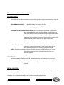
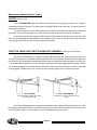
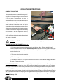
MECHANICAL
EARTH DRILLS
OPERATORS MANUAL
WITH
MAINTENANCE AND
PARTS INFORMATION
1-800-227-7515
0199
P.O. BOX 840
LIVINGSTON, TEXAS 77351
PHONE 936/327-3121
FAX 936/327-4025
Web: www.littlebeaver.com
E-Mail: [email protected]
MFG. BY: LITTLE BEAVER, INC. - LIVINGSTON, TEXAS USA
CUSTOMER SERVICE
Ph: 800/227-7515 or 936/327-3121 or Fax 936/327-4025
ORDERS...
Place your orders by telephone, fax, or mail. When calling, please have your parts
manual handy for reference. Our hours are 8:00 am - 4:30 pm central time, Monday thru
Friday. When ordering by mail or fax, include a description and LITTLE BEAVER part
number for the items you are ordering, your return address, and payment or your
authorization for COD shipment.
All orders are shipped UPS where possible. Freight charges will be added to your invoice.
Some items are oversize, resulting in a higher shipping cost. Power units and larger
augers are shipped via motor freight due to their weight.
PAYMENT TERMS...
COD, Cash in Advance, Visa, Mastercard or NET 30 with approved credit. COD limit for
new accounts is $500.00. Personal or company checks on new accounts will be held until
they clear the bank. To eliminate this delay, you may pay by wire transfer or send a
certified or cashiers check. For a NET 30 open account, please call or write for a credit
application.
SERVICE AND REPAIR...
Your LITTLE BEAVER Earth Drill has been designed for user repair with ordinary hand
tools. No special tools are required. Consult the appropriate section of the parts manual
for instructions.
Service or technical consulation is available, free of charge, from the factory in
Livingston, Texas. We will be pleased to help you with any problems or questions. Just
write, fax, or call. Our hours are 8:00am - 4:30pm central time, Monday thru Friday.
Factory repair is available. If you return a part to the factory, please include the following
information: Your name and return address, a description of the problem and payment
or authorization to return the repaired item COD for the repair and shipping charges.
RETURNS...
Please call the factory for a return authorization. This will help to ensure that your parts
are handled properly. Include your name and address, customer account #, invoice #
under which the returned parts were ordered, and a brief description of the problem with
the parts or the reason for returning them. Parts to be considered for warranty must be
returned to the factory for inspection within 10 days after receipt of replacement parts.
Be sure to prepay the shipping charges, we will not accept collect or COD packages.
Our mailing address...
LITTLE BEAVER, Inc.
2009 South Houston
P. O. Box 840
Livingston, Texas 77351
Page O-2
R
0196
SAFETY ALERT SYMBOL
The symbol shown above is used to call your attention to instructions concerning your personal safety.
WATCH THIS SYMBOL — It points out important safety precautions.
It means — ATTENTION! BECOME ALERT! YOUR PERSONAL SAFETY IS INVOLVED!
Read the message that follows and be alert to the possibility of Personal Injury or Death!
WARNING: The Engine Exhaust from this product contains chemicals
known to the State of California to cause cancer, birth defects or other
reproductive harm.
llllllllllllllllllllllllllllllllllllllllllllllllllllllllllllllllllllllllllllllllllllllllllllllllllllllllllllllllllllllllllllllllllllll
1 YEAR LIMITED WARRANTY
For 1 year from purchase, LITTLE BEAVER, INC. will replace for the original purchaser,
free of charge, any part or parts, found upon examination by any factory authorized service
center, or by the factory at Livingston, Texas, to be defective in material or workmanship or
both. If your equipment cannot be repaired, it will be replaced. All transportation charges on
parts submitted for replacement under this warranty must be borne by purchaser.
There is no other express warranty.
Implied warranties, including those of merchantability and fitness for a particular purpose,
are limited to 1 year from purchase and to the extent permitted by law. Any and all
implied warranties are excluded. This is the exclusive remedy and liability for
consequential damages under any and all warranties are excluded to the extent
exclusion is permitted by law.
*Notice: Engines are warrantied by the manufacturer of the engine. See separate engine
warranty enclosed.
llllllllllllllllllllllllllllllllllllllllllllllllllllllllllllllllllllllllllllllllllllllllllllllllllllllllllllllllllllllllllllllllllllll
MACHINE SERIAL NUMBER
The machine serial number for your mechanical Earth Drill is located on the carrier. For your convenience, when
requiring service or parts information, refer to this number and your model number. Record the model number,
engine make, machine serial number and date of purchase in the space provided below:
MODEL NUMBER
MACHINE SERIAL NUMBER
1004
ENGINEMAKE
DATE OF PURCHASE
Page O-3
R
TABLE OF CONTENTS
OPERATORS MANUAL
Page #
O-2
O-3
O-4
O-5
O-6
O-7
O-8
O-9
O-10 & 11 & 12
O-13
Service Information
Safety Alert, Warranty and Machine Information
Table of Contents
Safety Instructions
Maintenance and Lubrication, Transmission
Maintenance and Lubrication, Flexible Shaft
Maintenance and Lubrication, Clutch and Throttle Bracket
Troubleshooting
Operating Instructions
Decal Location
PARTS MANUAL
Page #
P-1
P-2 & 3
P-4 & 5
P-6 & 7
P-8
P-9
P-10 & 11
P-12 & 13
P-14
P-15 & 16
P-17
P-18
P-19 & 20
Inside Back Cover
Mechanical Parts Manual, Notes
5HP Engine Assembly
7-8HP Engine Assembly
Handle Torque Tube and Wires
Flexible Shaft
Flexible Shaft Dis-assembly & Assembly Instructions
Transmission
Transmission Dis-assembly & Assembly Instructions
Clutch
Auger Information
Extensions & Adaptors
Notes
Prices for Mechanical Parts and Augers
Torque Information and Conversion Chart
Page O-4
R
0196
SAFETY INSTRUCTIONS
DANGER: Failure to observe safety instructions and reasonable safety practices can
cause Property Damage, Serious Bodily Injury and/or Death. BE CAREFUL!! WATCH OUT FOR
BYSTANDERS!!
DANGER: NEVER drill holes where there is a possibility of underground power cables or other haz
ards. The exact location of underground services must be determined prior to drilling. Inadvertent
severing of telephone, fiber optic or CATV transmission cable, or damage to sewer pipe is costly;
RUPTURING OF GAS OR WATER LINES CAN CAUSE SERIOUS BODILY INJURY AND/OR DEATH.
COMING INTO CONTACT WITH BURIED POWER LINES CAN CAUSE SERIOUS BODILY INJURY,
SEVERE BURNS, AND/OR ELECTROCUTION. Call local utility companies or your local "One-Call"
number at least 48 hours before digging and have underground utilites marked.
DANGER: NEVER run engine inside building or enclosed area. Exhaust gases contain carbon
monoxide, an odorless and deadly poison.
WARNING: Augers are not to be used as anchoring devices.
CAUTION:
1. READ and understand this operator’s manual and the operator’s manual
for the engine.
2. NEVER Operate drill without correctly installing torque tube.
3. NEVER Remove auger from hole while auger is turning.
4. NEVER Operate auger at less than full throttle.
5. NEVER Operate drill with damaged auger or other damaged or missing parts.
6. KEEP Hands, Feet and Clothing away from moving parts while engine is running.
7. KEEP All safety shields and devices in place.
8. MAKE Certain everyone is clear before operating the machine.
9. KEEP leg pad against leg while drilling to maintain safe control.
10. WEAR SAFETY GLASSES.
11. KEEP Bystanders at least 10 feet away from work area.
12. SHUT OFF Engine to adjust, service or clean the machine.
NOTICE
It is the responsibility of the contractor, owner and user to maintain and operate the Earth Drill in compliance with
operating instructions provided. Observe all listed safety instructions and other reasonable safety practices. LITTLE
BEAVER, INC. accepts no responsibility for damages to this machine, and other property damage and/or bodily
injury due to careless or improper operations.
LITTLE BEAVER, INC. does not recommend or condone use of replacement engines greater than eight (8)
horsepower.
LITTLE BEAVER, INC. does not recommend or condone any unauthorized modifications to the earth drill, especially
those which would eliminate or reduce the effectiveness of the torque tube.
LITTLE BEAVER, INC. reserves the right to make changes in design and changes for improvements upon its product
without imposing any obligation upon itself to install the same upon its products theretofore manufactured.
Your operators manual offers recommendations for prolonged and satisfactory service.
0798
Page O-5
R
MAINTENANCE AND LUBRICATION
Engines are shipped without oil or gasoline. Refer to MANUFACTURER'S INSTRUCTIONS for proper
procedures and recommended fluids.
The TRANSMISSION and FLEXIBLE SHAFT are shipped fully oiled/greased and READY FOR USE. Refer
below for proper maintenance and lubrication instructions. Refer to the associated repair parts section for
proper disassembly and assembly instructions.
SHUT OFF ENGINE to adjust, service or clean the machine.
All nuts, fasteners and fittings must be kept properly torqued.
TRANSMISSION:
The transmission oil should be checked each day prior to operation, and during the day as conditions warrant.
RECOMMENDED OIL: Amalie Tri-Vis Plus Oil 80/85/140
Available in quart bottles, individually or
in case of 12. ORDER PART #10280.
If this oil is not available, it is very important that you use a high
quality gear oil.
LUBRICATING INSTRUCTIONS:
When adding oil to the transmission, hold
the transmission so that the top is level,
then remove the pipe plug (Item A, see
figure 1) and squeeze oil into transmission
until oil just comes out of the hole. Replace
pipe plug and tighten to10 ft lbs.
A
FIGURE 1
WARNING: Failure to securely replace pipe plug (A) may allow it to back out of the hole during
operation. This could result in serious bodily injury to the operator or bystanders.
Page O-6
R
604
Maintenance and lubrication...(cont.)
FLEXIBLE SHAFT:
The flexible shaft should be examined every 50 hours of operation and greased if necessary, using the
recommended grease.
RECOMMENDED GREASE:
Lubriplate Portable Tool Grease - GR-132
Available in 10 ounce Tubes, individually or in case of 12.
ORDER PART # 9070-L.
CLEANING AND GREASING INSTRUCTIONS: Follow the instructions provided for proper flexible
shaft dis-assembly (See page P-9 of Parts Manual and follow steps 1, 2,
4 & 5). After the flexible shaft core has been removed, wipe off the old grease
with a cloth. Clean the inside of the flexible shaft housing by pulling a clean
rag through with a long piece of wire. It may be necessary to make several
passes before all grease is removed. Then apply a light coat of
recommended grease to the core
and re-assemble. DO NOT overlubricate, as this will cause excessive heat to build up in the shaft.
INSPECTION: HOUSING - Check for tears or breaks in the rubber casing. Small tears may be
repaired by covering with duct tape or shrink tubing. If deep cuts are
found and the wire braid is torn, the housing should be replaced.
CORE - Check for broken wires and kinks. The core should be replaced if a broken wire is found.
Small kinks or twists are OK but if a sharp kink is found, the core
should be replaced.
IMPORTANT: Excessive amounts of grease inside the flexible shaft assembly will cause the shaft to produce
excessive heat and reduce the shaft's life. If the shaft becomes over-heated (too hot to touch), it
must be cleaned, inspected (see above) and re-greased. It is also important to follow the proper
procedure when greasing the transmission so that excess grease is not forced into the flexible shaft
assembly.
DECAL LOCATION:
The decals which are provided with your machine are shown at the rear of this manual. The decals are
important and should be maintained in good condition in the locations as described. If any of the decals are missing
or illegible, order replacement kit #9020-O and install before operating the machine.
0396
Page O-7
R
Maintenance and lubrication...(cont.)
CLUTCH: (See pg. P-13)
Your LITTLE BEAVER Earth Drill utilizes a centrifugal clutch to engage the auger as the engine is
accelerated from idle to full speed. The clutch begins to engage at about 2100 to 2200 rpm, so engine idle should
be kept below 1900 rpm.
The clutch requires no routine maintenance, but should be inspected when the flexible shaft is lubricated
(see above). If excessive slippage occurs, check the shoes and drum and clean or replace if necessary.
If the auger turns when the engine is at idle, first check the engine for proper idle speed (1900 rpm). Also
check the throttle linkage as indicated below. If the problem persists, check for stretched, discolored or broken
clutch springs and/or broken clutch shoes and replace if necessary.
THROTTLE CABLE AND THROTTLE BRACKET ASSEMBLY: (See pg. P-2/3 OR P-4/5)
ADJUST WITH ENGINE OFF. Inspect the throttle cable and throttle bracket assembly before each use
or if abnormal operation is noticed while operating the earth drill. The throttle lever should pull smoothly and freely
with no binding. The throttle wire should be adjusted so that there is minimal slack at the idle position (no more than
1" movement at the end of the lever). Then check that the throttle bracket is fully engaged before the lever "bottoms
out" against the handle bar. Also check that the clip moves smoothly over the rivet head (see "A") when the throttle
is fully engaged. If binding does occur, remove the clip and twist it slightly, then re-install and re-check.
A
IDLE POSITION
Rivet pulls tightly against clip, forcing
governer arm to idle.
FULL ENGAGEMENT
Clip slides over rivet as governor arm is
moved.
Note: The 5HP Briggs & Stratton models (standard black engine or Industrial/Commercial only) do not use
the sliding clip. With these models, check that the moving arm on the bracket pulls away from the governor arm
in the full throttle position. In the idle position it should push against the governor arm.
Page O-8
R
1298
TROUBLESHOOTING
TROUBLE
CAUSE
Engine will not start.
1.) Toggle Kill Switch on handle is off.
2.) Torque tube is not connected at engine end.
3.) “Oil Guard” protected engines must be filled with oil
to full mark on dipstick or to point of overflowing.
4.) If the light inside the engine on/off switch flashes (Briggs & Stratton
only), this is an indication that the oil level is low.
5.) Fuel level is too low in gas tank.
6.) Spark Plug is fouled.
Cannot Connect or Disconnect
Auger.
1.) Foreign Matter clogging adaptor.
2.) Spring and button in top of auger is bent or broken.
3.) Adaptor is bent.
Auger turns too slowly and will
not dig.
1.) Too much downward pressure or binding on side of
hole. Hold back, if necessary, to allow auger to turn
at full speed.
Auger turns but will not dig.
1.) Foreign matter collected around point.
2.) Point or blade is dull.
3.) Use carbide blade for hard pan soil.
Auger with extension will not dig.
1.) Auger or extensions bent or running out of line.
Transmission over-heats.
1.) It is normal for the transmission to run hot to the
touch. If it is very hot, check for proper oil and
free turning.
Auger turns when engine idles.
1.) Engine idle is set too high.
2.) Sliding wire clip on throttle bracket stuck. (should
move freely when throttle lever is closed.)
3.) Clutch Spring broken.
Page O-9
1298
R
OPERATING INSTRUCTIONS
CONNECT TORQUE TUBE
FIGURE 2
The torque tube consists of a steel tube approx. 66"
long with a 1-1/2" square fitting on one end. Part #2
is 29" long with a pivot hole on one end. To
assemble, slide the other end of the tube onto the
torque arm rod extending from the transmission as
shown in figure 2. Attach the square end of the
torque tube to the engine bracket as shown in figure
3. Make sure that the safety kill switch is pushed in
and that the snap button is aligned with the mating
hole provided so that the snap button securely
snaps into place.. Attach the other end to the
handle using the nylon bushings, shoulder bolt and
lock washer, (included).
WARNING:
FIGURE 3
NEVER use the Earth Drill unless the torque tube is properly connected.
BEFORE STARTING THE ENGINE,_Be sure that:
1.) Engine is properly prepared to Manufacturer’s specifications. Note: Engines with “Oil Guard”
protection must be filled with oil to the full mark on dipstick or to point of overflowing to allow the engine
to start. If the light inside the engine on/off switch flashes (Briggs & Stratton only), this is an indication
that the oil level is low.
2.) The torque tube is properly attached.
3.) There is no auger connected to the handle.
4.) The safety kill switch is in “ON” position on the handle and the Torque Tube has engaged the safety
kill switch at the engine bracket.
TO START THE ENGINE: Set the choke lever to the “ON” position and pull the starter rope. The engine should
start after 2 or 3 pulls. Set the choke lever to the “OFF” position and allow the engine to warm-up for 2 or 3 minutes.
If the engine does not start, re-check all safety kill switches, then refer to the engine manufacturers operator manual.
NOTE: If it is necessary to 'gas' or 'rev up' the engine while starting, push slightly with your thumb against
the bell crank on the throttle bracket. (The bell crank is the pivoting triangular plate to which the throttle wire, spring
and clip are attached.) This will release spring tension against the governer and allow the carburetor to open slightly.
DO NOT push directly against or try to move the carburetor butterfly or idle screw. Doing so will bend the
governer linkage rod.
Page O-10
R
0604
AFTER THE ENGINE HAS WARMED UP, Insert
the auger into the drive adaptor on the bottom of the
handle. Make sure the snap button and hole provided in the adaptor are aligned and the button
snaps securely into place. Hold the handle so your
left index finger can operate the throttle. Grasp the
right handle bar with your right hand. Stand so the
auger is straight up-and-down and is properly positioned to dig your hole (see figure 4). Note the
safety instructions in this manual and on the machine’s decals.
NEVER Drill holes where there is a possibility
of underground power cables or other hazards.
FIGURE 4
MAKE certain everyone is clear before operating the machine.
KEEP hands, feet and clothing away from moving parts while engine is running.
START THE AUGER TURNING By pulling the throttle lever in completely. Always allow the auger to turn at full
speed and let it cut its way into the soil.
IMPORTANT: When digging in soft soil, hold up slightly on auger. In hard pan, apply pressure, but not enough to
stall the auger or slow it down significantly. The auger works best when it turns at full speed.
IF THE AUGER STALLS repeatedly or slows down significantly; stop the auger by releasing throttle lever, slightly
lift up on auger, start auger by pulling throttle lever, and allow the auger to turn at full speed while slowly lowering
it to bottom of hole. When the desired depth is reached, stop the auger by releasing the throttle lever. Then pull the
auger completely out of the hole.
NEVER Remove auger from hole while auger is turning.
IMPORTANT: Keep the back as vertical as possible by bending the legs, as required, during the operation and lifting
procedure.
AUGER EXTENSIONS
If greater hole depths are required, extensions may
be used with the auger. After the auger has reached
its maximum depth, stop the auger and disconnect
the drive adaptor from the auger which remains in
the hole. Connect the extension to the auger as
shown in figure 5. Connect the drive adaptor to the
extension and continue to dig the hole.
When the desired depth is reached, stop the auger
and disconnect the drive adaptor from the extension. Then remove the extension (s) and auger
from the hole.
FIGURE 5
Page O-11
0604
R
NOTE: If the auger becomes lodged in roots, rocks, or other underground obstructions, and cannot be pulled
free; disconnect the handle from the auger and turn the auger counter-clockwise. It may be necessary to use a pipe
wrench to turn the auger. If the auger cannot be dislodged by turning counter-clockwise, it may be necessary to
manually dig the auger free.
WHEN WORKING WITH CUTTING BLADE, Point and Auger Flighting, be careful not to be cut by
sharp edges.
STANDARD CUTTING BLADE & POINT
A
Check the cutting blade (item A, Figure 6) on the
auger frequently. If it becomes dull, it may be
reversed to use the other cutting edge. If the
outside of the blade wears even with the auger
flighting, replace the blade or rebuild it with a
hardsurfacing rod. This is very important to reduce
auger flighting wear and damage. The point (Item
B, Figure 6) should be replaced when it loses its
cutting shape.
B
FIGURE 6
OPTIONAL CARBIDE BLADE:
An optional carbide blade is available for auger
sizes 1-1/2" thru 12". It is designed for use in
smooth hard-pan soils, asphalt or frost. It is not
recommended for use in rocky soils. The 4"
thru 12" carbide blade bolts on to the auger in
place of the standard point. The standard blade
is not used.
(4-12")
Mount the blade to the auger using the
included 3/8" x 1-1/4" bolts and nylon locknuts. Use a framing square to carefully align the
blade at 90 degrees to the auger. Tighten the
nuts slowly until snug, then re-check alignment
and adjust if necessary. Torque the bolts to 45
ft. lbs.
`
CAUTION: If the blade is not installed properly, mis-alignmant may cause the auger to vibrate
and "walk" in use.
ATTACHMENTS:
Several attachments are available for your LITTLE BEAVER Earth Drill; including both wet and dry type
horizontal boring kits and a drill chuck adaptor which allows you to use a wood bit. Refer to the specific
operating instructions supplied with the attachment. If these become lost or misplaced, replacements may
be obtained from the factory.
Page O-12
R
0196
DECAL LOCATION
D
E
H
F
G
Handle Decal
F
D
G
E
FOR DECAL SET,
ORDER KIT #9020-O for machines with Oil Bath Transmission
ORDER KIT #9020-D for machines with Grease lubricated Transmission
which also includes the Decals for the Handle.
Page O-13
1110
R
5 HP ENGINE ASSEMBLY
1
4-A--
7
/
8 ---
4--29 --5
11 ---
15---
10 ---
1A
---17
7---
---16
9----- 8
11 --20 --19 --18 ---
6
--- 14
12
/
2
---8
---19
---23
21---
2X
/
7
---37
/
9
---19
/
38
---22
3
---11
---13
7---
24--9 --28 -----25
---8
11-----14
26 ---
---27
---26
30 --/
32
10" Pneumatic
wheel, 3/4" Axle
Page P-2
R
---25
/
33
/
34
/
35
--36
0104
5 HP ENGINE ASSEMBLY
ITEM
1
1A
2
2X
3
4
4A
5
6
7
8
9
10
11
12
13
14
15
16
17
18
19
20
21
22
23
24
25
26
27
28
29
30
31
32
33
34
35
36
37
38
0104
PART #
DESCRIPTION
3085-A
3082-A
3082-V
3084-A
---------
Throttle Bracket Assy. 5HP B&S & B&S I/C (Industrial/Commercial)
Throttle Bracket Assy. 5 HP B&S Industrial Plus
Throttle Bracket Assy. 5.5 HP B&S Vanguard Engine
Throttle Bracket Assy. 5.5 HP B&S INTEK Pro Engine
Obsolete, order #TCO-5H Throttle Bracket Change-over Kit
Includes Spring Anchor Assy.(2X), Throttle Wire, Housing, and Loom
Spring Anchor Assy. 5HP Honda Direct Throttle Hook-up
Throttle Bracket Assy. 5 HP Wisconsin W1-185
Handle - Motor Carrier, 5HP B&S & B&S I/C ONLY
Handle - Motor Carrier, 5 & 8HP B&S Intek Pro ONLY
Handle - Motor Carrier, 5 & 8HP Honda ONLY
Torque Tube Bracket Assy. - Engine End
Clutch Bracket Assy. Model 5
Spring
Screw, 10-32 x 1/4"
S-Hook
Clip, 5HP B&S Industrial Plus Engine
Clip, 5.5HP Vanguard
Clip, 5HP B&S Intek Pro Engine
Nut 5/16-18 (Nut w/Lockwasher)
Clip, 5HP Honda GX140/GX160
Clip, 5HP Wisc. W1-185
Screw 5/16" x 3/4" G5, Hex NC
Kill Switch, Torque Tube
Spring & Button
Spacer
Clamp (incl. 2 ea #9027-10, 3002-C & #30318)
Lock Washer, 5/16"
Nut, 5/16"-18, w/Nylon Insert Lock
Screw 5/16"-18 x 1-1/4"
Screw 5/16" x 7/8", Hex SAE
Screw 5/16" x 1 1/4" GR5, Hex SAE
Motor Carrier
Screw 5/16" x 1-1/2" NC
Wheel, 8" (incl. #3006-1)
Cap-Axle Snap (incl. w/#3004)
Flat Washer
Governer Control, 5HP B&S
Carrier ONLY, Medium Clearance for 5.5HP Vanguard Engine
Spacer, 1-5/8"
Axle
Spacer, 3-1/8"
Wheel, 10" Pneumatic
Flat Washer 3/4"
Cotter Key, Wheel, 1/8" x 1"
Screw, 10-32 x 3/8 Machine
Spring, Throttle 5Honda Direct Hook-Up and Throttle Lever
3092-A
3050-A
3000-C
3000-CD
3000-CDH
9084-G
3011-MA
4041-2H
3010-8
3010-7
3010-5B
3010-2
3010-5I
3002-KEP
3010-H
3010-4
3012-1T
3007-9
9058
9084-1
4018-2H
3002-C
30318
9027-10
3012-1
9084-2
3000-B
3002
3004
3006-1
3004-A
3087
3000-EV
3031-A
3030
3031-B
30258
30164
30163
5079
4041-2
QTY
1
1
1
1
1
1
1
1
1
1
1
1
1
1
1
1
1
1
4
1
1
2
1
1
1
1
6
2
2
2
2
1
4
4
4
4
1
1
2
2
2
4
4
4
1
1
Page P-3
R
7 & 8 HP ENGINE ASSEMBLY
1
1A
11 12
/ /
10---
---6
/
9
/
8
7
/
2
/
6
8
25 \
\
10
/
6---
---13
12--11---
---10
12---
26---
11--3
37-A-
37---
4
---6
12---
17---
---10
11--10---
23
14
---16
---15
3X
3A
20--8--18---
5
---6
12---
11--26 ---
---10
--- 13
---19
3B
---22A
21---
/
6
---19
---22
---10
12---
---26
--8
11---
13---
24--31
/
8" Wheel
1/2" Axle
---26
---25
30 --/
28
/
32
/
27
/
29
10" Pneumatic
wheel, 3/4" Axle
---25
/
33
/
34
/
35
--36
Page P-4
R
903
7 & 8 HP ENGINE ASSEMBLY
ITEM
1
1A
2
3
3A
3B
3X
4
5
6
7
8
9
10
11
12
13
14
15
16
17
18
19
20
21
22
22A
23
24
25
26
27
28
29
30
31
32
33
34
35
36
37
37A
1009
PART #
DESCRIPTION
3010-D
3065-A
3095-A
---------
Throttle Bracket Assy. 7 HP B&S Engine
Throttle Bracket Assy. 8 HP B&S Industrial Plus Engine
Throttle Bracket Assy. 7 HP Wisconsin Engine
Obsolete, order #TCO-8H Throttle Bracket Change-over Kit
includes New Guide (3X), Throttle Wire, Housing, Loom and spring
Throttle Bracket Assy. 7.5 HP B&S Vanguard Engine
Throttle Bracket Assy. 8 HP B&S INTEK Pro Engine
Cable Guide Assy. 8HP Honda Direct Throttle Hook-up
Torque Tube Bracket Assy. - Engine End
Clutch Bracket Assy. Model 7
Clip
Clip, 8 HP Intek (and 5HP Honda)
Clip, 8HP Honda
Clip, 8HP B&S Industrial Plus Engine
Clip, 7.5 HP B&S Vanguard Engine
Spacer
Lock Washer 5/16"
Screw 5/16" x 2" NC Grade 2
Screw, 10-32 x 1/4"
S-Hook
Spring
Spring, 7.5 Vanguard
Screw 5/16" x 3/4" Grade 2
Spring, Throttle 8 HP Honda Direct Hook-Up and Throttle Lever
Spring & Button
Spacer
Kill Switch, Torque Tube
Clamp (incl. 2 ea #9027-10, 3002-C & #30318)
Lock Washer, 3/8"
Nut 5/16"-18 Nylon Insert Lock
Screw 5/16"-18 x 1-1/4"
Screw 3/8" x 1" NC (Bottom)
Screw 3/8" x 1 1/4" Hex NC GR5 (Top)
Screw, 10-32 x 3/8 Machine
Carrier (incl. 4 #3004-A)
Cap Screw 5/16" x 1-3/4" NC
Nut 5/16-18 (Nut w/Lockwasher)
Wheel, 8" (incl. 3006-1)
Flat Washer
Cap-Axle Snap (incl. w/#3004)
Carrier ONLY, Medium Clearance
Carrier ONLY, 8 HP B&S INTEK
Spacer, 1-5/8"
Axle
Spacer, 3-1/8"
Wheel, 10" Pneumatic
Flat Washer 3/4"
Cotter Key, Wheel, 1/8" x 1"
Handle, Motor Carrier, 7HP B&S Engine ONLY
Handle, Motor Carrier, with Decal, 5 & 8 HP B&S Intek Pro ONLY
Handle, Motor Carrier, with Decal, 5 & 8 HP Honda ONLY
3088-A
3055-A
3063-A
9084-G
3011-HMA
3010-4
3010-H
3010-4H
3010-5B
3010-2
3010-10
3002-C
3010-9
3010-8
3010-7
4041-2H
3096
3012-1T
4041-2
9058
9084-1
3007-9
4018-2H
3012-3
30318
9027-10
3012-2
9027-8
5079
3000-B
3002-A
3002-KEP
3004
3004-A
3006-1
3000-E
3000-G
3031-A
3030
3031-B
30258
30164
30163
3000-C7
3000-CD
3000-CDH
QTY
1
1
1
1
1
1
1
1
1
1
1
1
1
1
1
4
1
1
1
1
1
2
1
1
1
1
1
4
2
2
2
2
1
1
4
6
4
4
4
1
1
2
2
2
4
4
4
1
1
1
Page P-5
R
HANDLE, TORQUE TUBE AND WIRES
1
---4
5*-11
6--
---9*
---8
/
30
---2
3---
---10
12
13
/
14
/
---19
---18
---4
---15
---17
---16
* Note: All bolts to the transmission housing
should be tightened to 24 ft lbs torque
23
/
24
/
22
\
24
/
25
/
26
/
---27
---28
21
\
---35
20
\
---31
---32
33
Page P-6
R
050803
ITEM
HANDLE, TORQUE TUBE AND WIRES
PART #
DESCRIPTION
QTY
1
10428-A
Handle, Loop includes Switch and Throttle Lever
1
If your machine is not equipped with this handle, but is the Oil Bath Transmission, you can upgrade
by ordering part # HCO-M# which would include the handle assembly and the new transmission lid.
2
10429
Clamp, Bushing, Right
1
3
10460
Leg Pad
1
4
10440
Handle Grip, Left & Right
2
5
10306
Socket Head Cap Screw, 5/16 -18 x 3/4
1
6
3002-C
Washer, 5/16 Split Lock, Heavy Plated
4
7
10305
Washer, 5/16 Flat
4
8
3010-8
Screw, 10-32 x 1/4"
1
9
3002-A
Screw, 5/16 x 1-3/4 Hex Head Cap Screw
1
10
30318
Nut, Nylon Lock, 5/16"
1
11
10470
Kill Switch Assembly
1
12
4031-1
Throttle Lever Assembly
1
13
4041-2
Spring, Return, Throttle Lever
1
14
4033
Rivet
1
15
4033-1
Flat Washer, #10
1
16
4034-A
Screw, 10-32 X 5/8"
1
17
4034-1
Flat Washer, 3/16", 1/4" Standard
11
18
4034-2
Lock Washer, #10, External
1
19
4034-3
Nut, 10-32 Hex
1
20
9058-1
Button Shield
1
21
10340
Torque Tube, Female, 69" long
1
22
10350
Torque Arm, Male end
1
23
10360-R
Bushing Repair Kit (incl. 2 Bushings, Washer & Shoulder Bolt)
1
24
10360
Bushing, Torque Arm
2
25
10380
Internal Star Washer, 5/8"
1
26
10370
Shoulder Bolt, 5/8" x 1 3/4"
1
27
3007-6
Kill Switch Wire-Long
1
3007-6B
Kill Switch Wire-Long-5HP B&S ONLY
1
3007-6H*
Kill Switch Wire-Long 5 & 8HP Honda Direct Throttle
1
3007-8W
Kill Switch Wire-Long 5,7&8HP Wisc./Honda/B&S Ind Plus,
1
8HP Intek & 5.5 Vang.
28
3007-8
Kill Switch Wire-Short
1
30
10520
Washer, Belleville
1
31
3007-6P
Wire Loom, Briggs & Stratton
1
3007-H*
Wire Loom, Honda and 7.5 Vanguard
1
32
3007-5
Plastic Tie
5
33
9090-W
Wire Splicer, Wisc., Honda & B&S Industrial Plus Only
1
34
10302
Screw, 5/16 x 1-1/4 Socket Head
4
35
3089
Throttle Control Assembly (inc. 3008 & 3009) 109" OAL
1
3089-5H
Throttle Control Assembly 115" OAL 5HP Honda Direct Throttle 1
3089-8H*
Throttle Control Assembly 119" OAL 8HP Honda Direct Throttle 1
* For 7.5 HP Vanugard Engine (138432-0035-A1)
Page P-7
1009
R
FLEXIBLE SHAFT
2
/
ITEM
4
/
3
/
6
/
5
/
7
/
6
/
5
/
8
/
9
/
10
PART #
DESCRIPTION
QTY
3224
Flexible Drive Shaft Assembly, Complete
1
2
3124-1
Housing, Flexible Drive Shaft
1
3
3224-2
Core, Flexible Drive Shaft (inc. #4019, #3024-16 & #3124-19)
1
3224-2EA
Core with End Assembly
4
4019
Key (inc. w/#3124-2)
1
5
3024-16
Lock Ring-Inner, End Assembly (inc. w/#3124-2)
2
6
3024-13
Bearing
2
7
3124-19
Spacer (inc. w/#3124-2)
2
8
3024-15
Lock Ring-Outer, End Assembly
2
9
3024-17
Knurled Housing, End Assembly
1
10
3124-4
End Assembly Kit
1
RECOMMENDED GREASE:
Lubriplate Portable Tool Grease (GR-132)
Available in 10 oz. tube form, also in case of 12.
ORDER PART #9070-L
IMPORTANT: Shafts should be examined every 50 to 100 hours of use and greased if
necessary, using recommended grease.
GREASING INSTRUCTIONS: Follow steps 1, 2, 4 & 5 of the Flexible Drive Shaft DisAssembly instructions on the following page.
Page P-8
R
0706
FLEXIBLE SHAFT DIS-ASSEMBLY
1. REMOVE KILL SWITCH WIRE & THROTTLE WIRE
A. Disconnect at throttle lever.
B. Loosen anchor bolt on handle.
C. Pull kill switch wire from kill switch.
D. Un-wrap wires from flexible shaft and lay aside.
B
A
B
2. DETACH SHAFT FROM TRANSMISSION
A. Loosen two bolts on clamp #4018-2H (Item A in
step 3) so that end assembly can turn.
B. Using a pipe wrench, hold #10150 (silver)
retainer in place. NOTE: Do not unscrew the
10150 retainer from the transmission housing. If
it does unscrew, use caution in re-inserting it. The
aluminum threads are easily damaged or crossthreaded.
C. With a second pipe wrench, turn the (black)
flexible shaft COUNTER-CLOCKWISE to loosen
and remove.
C
3. TO DISCONNECT COMPLETE SHAFT ASSEMBLY
A. Remove clamp #4018-2H from clutch bracket.
B. Pry clutch drum loose, freeing clutch drum and
complete shaft assembly from power unit.
C. To detach clutch drum from shaft, loosen two
allen screws on clutch drum and pry loose
from shaft.
A
C
C
B
4. TO REMOVE FLEXIBLE SHAFT CORE AND
HOUSING ONLY
A. Complete steps 1 and 2 above.
B. Hold flexible shaft end piece in place with pipe
wrench.
C. Using a second pipe wrench, turn flexible shaft
housing COUNTER-CLOCKWISE freeing it from
the end assembly.
D. To remove core from end assembly, complete
step 3. Remove key and outer snap ring, slide
knurled housing down, remove outer bearing and
spacer. Remove lock ring bearing and lock ring.
5. RE-ASSEMBLY
A. BEFORE re-assembling core and housing of
flexible shaft, remove all old grease.
B. Re-grease by applying grease to core while
inserting into flexible shaft housing.
(Recommended grease-Lubriplate Portable Tool
Grease - Order Part #9070-L)
C. After greasing, re-assemble by reversing disassembly procedures.
Page P-9
0798
R
37
TRANSMISSION
OIL BATH
2--3---
30--27--28---
4---
27--28--29--25--2728-
27--28--29---
6-----26
5---
---6
30-----27
---28
---29
1---
7---
---22
8---
27---
---18
28--29---
---28
---29
---20
---19
9---
1---
9---
---38
11-----36
12
\
13
\
14
\
17
\
A
---21
31--35---
32--33--28--34--Page P-10
R
1006
TRANSMISSION, OIL BATH
ITEM
PART #
1
2
3
4
5
6
7
8
9
11
12
13
14
17
18
19
20
21
22
25
26
27
28
29
30
31
32
33
34
35
36
37
38
DESCRIPTION
QTY
10010
Transmission Assy.10:1 w/Adaptor, less Handle and Torque Arm
10020
Transmission Assy.20:1 w/Adaptor, less Handle and Torque Arm
10030
Transmission Assy.13.33:1 w/Adaptor, less Handle and Torque Arm
Transmissions for Loop handle following (see page P-6 of this manual for Loop Handle)
10010-L
Transmission Assy.10:1 w/Adaptor, less Loop Handle and Torque Arm
10020-L
Transmission Assy.20:1 w/Adaptor, less Loop Handle and Torque Arm
10030-L
Transmission Assy.13.33:1 w/Adaptor, less Loop Handle and Torque Arm
10040
Cover Plate
10041
Cover Plate for Loop Handle
10050
Bearing, Upper Main Shaft, #6205
10060
Spacer, Main Shaft
10070
Bronze Gear, 10:1 Ratio, 1-1/4" Bore, Double Keyed
10072
Bronze Gear, 20:1 Ratio, 1-1/4" Bore, Double Keyed
10075
Bronze Gear, 13:1 Ratio, 1-1/4" Bore, Double Keyed
10080
Main Shaft, includes 2 #10115 Seals
10090
Key Main Shaft - #806 Woodruff
10100
Bearing, Lower Main Shaft #6206
10130
Body, Casting
10115
Seal, Main Shaft #471736 (for new style main shaft of 1/95).
10140
Snap Ring, 1-3/4" External Housing Ring
10150
Coupling, Pinion Shaft, includes 10170 seal
10170
Seal, Pinion Shaft inc. w/10150 coupling
10180
Bearing, Front Pinion Shaft, #6905
10191
Pinion Gear Shaft, 10:1
10193
Pinion Gear Shaft, 20:1
10196
Pinion Gear Shaft, 13.33:1
KT4-1040
Screw, Socket Hd. 5/16 x 1-1/2
10210
Bearing, Rear Pinion Shaft #6302-RSR
10260
Pipe Plug
9021
Allen Screw 1/4"-20 x 1/4"
10230
O-Ring, Cover Seal (All-In-One)
10310
Vent Plug, Oil
10320
Deflector, Vent Plug
10300
Screw, Socket Head, 5/16" x 1" (If for Loop Handle, 2 must
be 1-1/4" Long, #10302 and 2 must be 1-1/2" long, #KT4-1040)
3002-C
Washer, 5/16" Split Lock
10305
Washer, 5/16" Flat SAE
10330
Dowel Pin, 1/4" x 1"
30272
Adaptor, Keyed Shaft to Auger, mounting hardware incl.
10520
Washer, Williams, 3/8"
10305
Washer, 5/16 Standard Flat
10490
Cap Screw, Socket Head, 5/16"-18 x 1" w/Locking Plug
9058-1
Button Shield, Only
4081
Key, Adaptor
10425
Handle Brace for 2 piece handle
30171
Set Screw, 5/16 x 5/16
1
1
1
1
1
1
1
1
1
1
1
1
1
1
2
1
1
2
1
1
1
1
1
1
1
2
1
1
1
1
1
1
10
10
7
2
1
1
1
1
1
1
1
1
WHEN ORDERING TRANSMISSION PARTS BE SURE TO INCLUDE SERIAL NUMBER OF
TRANSMISSION, LOCATED ON BOTTOM OF HOUSING
IMPORTANT: LUBRICATING INSTRUCTIONS Can be found on page P-13
Page P-11
0104
R
OIL BATH TRANSMISSION
INSTRUCTIONS FOR DIS-ASSEMBLING AND ASSEMBLING
(Refer to key #'s on Page P-6 & P-10)
TO DIS-ASSEMBLE:
1.Uncouple throttle wire and throttle wire housing. Remove kill switch wire.
2.Remove shoulder bolt #26, torque arm #22 and torque arm bushing #24 from transmission (see page 6).
Note: You may have to remove right handle clamp screw #5 before torque arm and bushings will come out.
3.Uncouple flexible drive shaft from retainer and coupling #12 by holding retainer with a pipe wrench and unscrewing drive shaft housing with a second pipe wrench. NOTE: the flexible drive shaft housing is black.
The retainer is unpainted. Break loose where these items join. (right hand thread)
4.Remove pipe plug #20 and drain oil from transmission.
5.Remove 8 bolts #9 and nuts #10 from handle clamps and cover plate #1. Remove right and left handles.
6.Remove 10 screws #27, flat washers #29 and lock washers #28 from transmission. Note the location
and orientation of the vent plug cover #26.
7.Tap the underside of the cover plate to remove it. Note the location of the O-rings for proper reassembly.
There are 8 #24 O-rings, 2 #23 O-rings and 1 #22 O-ring. Do not lose the O-Rings.
8.Remove vent plug #25 from the cover plate if it needs to be replaced.
9.Remove set screw #21, holding retainer #12. Unscrew retainer using a pipe wrench. (right hand thread)
10.Remove seal #13 from retainer #12 by pressing out from threaded end.
11.Loosen set screw #36 and remove screw #35, flat washer #33 and lock washer #34 from the adaptor #31.
Using a ball joint wrench, remove the adaptor from the main shaft #5 by tapping the wrench between the
housing and the adaptor. Try not to burr the housing if possible. Note screw #35 has a nylon insert, replace
it with the same type.
12.Using a small punch, tap on pinion gear/shaft #15 at shoulder A to remove it from the housing. Press
bearing #14 off of shaft.
13.Remove spacer #3 from main shaft.
14.Turn housing upside down and tap main shaft #5 out of housing.
15.Remove bearing #7 from housing by tapping or pressing out of housing.
16.Remove seal retainer ring #11 from housing, using snap-ring pliers.
17.Turn housing over and tap seals #9 out of housing.
18.Tap bronze gear #4 off of main shaft. Keys #6 will be free.
19.Using pilot bearing puller, remove bearing #19 if it needs to be replaced.
TO ASSEMBLE:
1.Press 2 seals #9 into transmission housing #8 (old style main shaft uses seal #472475 and #471733, new
style main shaft effective 1/95 uses 2 #471736 seals). Install seal retainer ring #11 into housing.
2.Press bearing #7 into housing.
3.Turn housing on the side and press bearing #19 into housing. Note: Be sure that Bearing #19 goes in
straight, since the housing is cast at an angle.
4. Screw pipe plug #20 into housing.
Page P-12
R
0904
Transmission Assembly Continued...
5.Press bearing #2 into cover plate #1.
6.Screw vent plug #25 into cover plate. Use teflon thread sealant tape on vent plug.
7.Tap keys #6 into main shaft #5, then press bronze gear #4 on main shaft.
8.Push main shaft, with gear, through bearing #7 and the seals.
9.Place spacer #3 on the main shaft, resting on the top of the bronze gear.
10.Press seal #13 onto coupling #12.
11.Hold housing secure and push pinion gear/shaft into the housing.
12.Place loctite on the threads of the housing and screw retainer #12 into housing and tighten with a pipe
wrench. This retainer is easy to crossthread, so line the threads up carefully. Replace and tighten set
screw #21 to secure retainer
13.Holding housing level, place 2 O-rings #23 over dowel pin holes and 8 O-rings #24 over bolt holes and
1 O-ring #22 in groove around top of housing.
14.Holding housing level, pour recommended oil (see page O-6) in housing. Oil level should come up to
the top of spacer #3.
15.Place cover plate #1 on the top of the housing. Tap lightly so bearing will go on main shaft. Be sure that
all O-rings stay in their proper places and do not fall into bottom of housing. Be sure they are fitting in their
groove.
16.Align dowel pin holes and push dowel pins #30 all the way into the housing.
17.Place vent plug cover #26 over vent plug and screw 2 screws #27 with lock washers #28 and flat washers
#29 on top of vent cover. Tighten to 24 ft. lbs.
18.Screw 8 screws #27 with lockwashers #28 and flat washers #29 into remaining holes. Tighten to 24 ft. lbs.
19.Tap key #37 onto main shaft. Then tap adaptor #31 on the main shaft . Insert Screw #35 with nylon insert,
lock washer #34 and flat washer #33 through adaptor into bottom of main shaft and tighten to 10 ft. lbs. Tighten
set screw #36 to secure key and adaptor.
20.Install torque arm #22 with 2 bushings #24 on both sides of torque arm into housing. Insert shoulder bolt
#26 with star washer #25 into housing and through holes in bushings and torque arm. Tighten to 100 ft. lbs.
21.Place left and right handles on cover plate. Using bolts #9 and nylon stop nuts #10 secure clamps and
handles to cover plate. Tighten to 10 ft. lbs.
22. Add recommended oil every day or as needed. Check oil level each day before use..
LUBRICATING INSTRUCTIONS: When adding oil to transmission, hold the transmission so that the top is
level, then remove the pipe plug (item #20) and squeeze oil into the transmission until oil just comes out of
the hole. Replace the pipe plug and tighten to 10ft.lbs. The transmission oil should be checked each day
prior to operation, and during the day as conditions warrant. The oil should be changed after the initial
25 hours of use and every 100 hours thereafter. *OIL CAPACITY: 1 US PINT*
RECOMMENDED OIL Amalie Tri-Vis Plus+ SAE 80W-85W-140 or Penzoil Multi
Purpose Gear Oil or equivalent. Available in quart size, also in case of 12.
ORDER PART #10280 OR #10280-A for Case
NOTICE: DO NOT CROSSTHREAD ITEM #12 COUPLING.
DOING SO WILL CAUSE THE END PIECE OF CORE TO BREAK!
Page P-13
0904
R
HEAVY DUTY CLUTCH
3
/
1
/
7
/
6
/
2
4
/
5
/
/
6
ITEM
1
1
2
3
4
5
6
7
7
PART #
DESCRIPTION
4375-F
4376-F
4179-F
4382
4383-F
4021-2F
4320
4080
4081
Rotor Assy. Model 5 - 3/4" Bore (incl. shoes, springs & set screws)
Rotor Assy. Model 7 or 8 - 1" Bore (incl. shoes, springs set screws)
Clutch Drum (incl. pilot bearing and set screws)
Clutch Spring
Clutch Shoe
Pilot Bearing
Set Screw (Rotor & Drum)
Key - Rotor Model 5
Key - Rotor Model 7 or 8
QTY
1
1
1
3
3
1
4
1
1
4383-KF
Repair Kit (incl. 3 Shoes and 3 Springs)
1
WARNING: DO NOT START ENGINE unless the clutch drum (Item #2) and flexible
shaft have been reassembled and clamped into the clutch bracket (See page 11).
Starting the engine without the drum in place will cause the clutch shoes to fly off,damaging
the machine and possibly causing severe personal injury.
NOTE: Rotor should be shoved all the way on the crankshaft. Put Loctite on #6 set screws and tighten securely. At full throttle, engine speed should not be less than 3600 RPM. Adjust engine idle to
release clutch when throttle lever is released. (Approximately 1900 RPM.)
NOTE: To remove rotor from crankshaft, use a ball joint tool. For 7 or 8 HP Models, use a backing plate be
tween the clutch bracket with the ball joint tool.
NOTE: When replacing engine, note that 7 & 8HP engine crankshafts are too long. Cut 1-1/4" off of crank
shaft.
Page P-14
R
0609
AUGERS & ACCESSORIES
ITEM
STANDARD AUGER
1
1
1.5X42-SSS
2.5X42B
2.5X42SP
2X36-SSS
2X42-SSS
3X36-SSS
3X42-SSS
4X36-SSS
4X42-SSS
5X36-SSS
5X42-SSS
6X36-SSS
6X42-SSS
7X36-SSS
7X42-SSS
8X36-SSS
8X42-SSS
9X36-SSS
9X42-SSS
10X36-SSS
10X42-SSS
12X36-SSS
12X42-SSS
14X36-SSS
14X42-SSS
16X36-SSS
16X36-SSSF
16X42-SSSF
1-1/2" X 42" Auger, Snap-on with Screw-on Point
2-1/2" X 42" Bucket Auger, Snap-on
2-1/2" x 42" Spiral Barrel Auger (Soil Sampling)
2" X 36" Auger, Snap-on with Screw-on Point
2" X 42" Auger, Snap-on with Screw-on Point
3" X 36" Auger, Snap-on with Screw-on Point
3" X 42" Auger, Snap-on with Screw-on Point
4" X 36" Auger, Snap-on
4" X 42" Auger, Snap-on
5" X 36" Auger, Snap-on
5" X 42" Auger, Snap-on
6" X 36" Auger, Snap-on
6" X 42" Auger, Snap-on
7" X 36" Auger, Snap-on
7" X 42" Auger, Snap-on
8" X 36" Auger, Snap-on
8" X 42" Auger, Snap-on
9" X 36" Auger, Snap-on
9" X 42" Auger, Snap-on
10" X 36" Auger, Snap-on
10" X 42" Auger, Snap-on
12" X 36" Auger, Snap-on
12" X 42" Auger, Snap-on
14" X 36" Auger, Snap-on
14" X 42" Auger, Snap-on
16" X 36" Auger, Snap-on
16" X 36" Auger, Snap-on, Full Flighted
16" X 42" Auger, Snap-on, Full Flighted
2
9023-4
9023-6
9023-8
9023-9
9023-10
9023-12
9023-14
9023-16
Blade for 4" & 5" Augers
Blade for 6" & 7" Augers
Blade for 8" Augers
Blade for 9" Augers
Blade for 10" Augers
Blade for 12" Augers
Blade for 14" Augers
Blade for 16" Augers
3
9027
9027-16
Point, Standard, Fits 4" thru 12" Augers
Point, Standard, Fits 14" and 16" Augers
4
9058
Spring & Button
5
9023-S4
9023-S9
9023-S12
9023-S16
Cap Screw & Nut w/Lockwasher, 4" - 8" Blades
Cap Screw & Nut w/Lockwasher, 9" - 10" Blades
Cap Screw & Nut w/Lockwasher, 12" Blades
Cap Screw & Nut w/Lockwasher, 14" - 16" Blades
6
9027-7
Cap Screw & Nut w/Lockwasher, Standard Points
--12
--2
5
6
1203
PART# DESCRIPTION
--3
Page P-15
R
ITEM
STANDARD AUGER
WITH CARBIDE POINT
7
9023-C1.5
9023-C2
9023-C3
9023-C4
9023-C5
9023-C6
9023-C7
9023-C8
9023-C9
9023-C10
9023-C12
Blade, Screw-on, w/Carbide for 1-1/2"Augers
Blade, Screw-on, w/Carbide for 2: Augers
Blade w/Carbide for 3" Auger, Inc. Mtng. Bolts/Nuts
Blade w/Carbide for 4" Auger, " " "
Blade w/Carbide for 5" Auger, " " "
Blade w/Carbide for 6" Auger, " " "
Blade w/Carbide for 7" Auger, " " "
Blade w/Carbide for 8" Auger, " " "
Blade w/Carbide for 9" Auger, " " "
Blade w/Carbide for 10" Auger, " " "
Blade w/Carbide for 12" Auger, " " "
8
9027-8S
Cap Screw & Lock Nut for Carbides (2 ea.)
9
6X36-SSP
6X42-SSP
7X36-SSP
7X42-SSP
8X36-SSP
8X42-SSP
9X36-SSP
9X42-SSP
10X36-SSP
10X42-SSP
12X36-SSP
12X42-SSP
6" x 36" Snap-on Auger w/Pengo Point & Blade
6" x 42" Snap-on Auger w/Pengo Point & Blade
7" x 36" Snap-on Auger w/Pengo Point & Blade
7" x 42" Snap-on Auger w/Pengo Point & Blade
8" x 36" Snap-on Auger w/Pengo Point & Blade
8" x 42" Snap-on Auger w/Pengo Point & Blade
9" x 36" Snap-on Auger w/Pengo Point & Blade
9" x 42" Snap-on Auger w/Pengo Point & Blade
10" x 36" Snap-on Auger w/Pengo Point & Blade
10" x 42" Snap-on Auger w/Pengo Point & Blade
12" x 36" Snap-on Auger w/Pengo Point & Blade
12" x 42" Snap-on Auger w/Pengo Point & Blade
10
9023-P35
9023-P35HS
9023-P1336
9023-P35CT
9023-5T30
9023-5T30C
Blade, Pengo #35 (1 per 6" & 7" Auger, 2 per 8"-12")
Blade, Pengo #35HFF Hardsurfaced (Both sides)
Blade, Pengo #1336 w/Carbide
Blade, Pengo w/Carbide
Blade, Pengo, Chisel Point
Blade, Pengo, Chisel Carbide Point
11
9027-P
9027-PC
Point, Pengo #SB25
Point, Pengo #SB-25C w/Carbide
12
FS-3
FS-4
FS-5
FS-6
FS-7
FS-8
FS-9
FS-10
FS-12
FS-14
FS-16
Flighting, replacement 3" x 37" or 60" Section
Flighting, 4" x 30" or 37" Section
Flighting, 5" x 30" or 37" Section
Flighting, 6" x 30" or 37" Section
Flighting, 7" x 30" or 37" Section
Flighting, 8" x 30" or 37" Section
Flighting, 9" x 30" or 37" Section
Flighting, 10" x 30" or 37" Section
Flighting, 12" x 37" Section
Flighting, 14" x 37" Section
Flighting, 16" x 19" Section
13
9062
9062-H
Auger Top for 4" thru 10" Augers
Auger Top for 12" thru 16" Augers
14
9062-1
9062-2
Extension Bottom for 4" thru 10" Extensions
Extension Bottom for 12" thru 14" Extensions
--7
8
Optional Carbide
Blade
Specify -SSC when
ordering Auger
PENGO AUGERS
---4
13--
9
--12
--10
11-AUGER REPAIR PARTS
Must be welded.
PART# DESCRIPTION
Page P-16
R
1203
ITEM
EXTENSION
15
15
13--
---4
---14
HEX AUGER/EXTENSION
16
16
17
17
ADAPTORS
Auger to Transmission
PART#
DESCRIPTION
9054
36" Tube Type Snap-on Extension
9054-A
18" Tube Type Snap-on Extension
9054-S1.5X36
1-1/2" x 36" Screw-on Ext.(Must use Screw-on Agr)
9054-S2X36
2" x 36" Screw-on Ext.(Must use Screw-on Auger)
9054-S3X36
3" x 36" Screw-on Ext.(Must use Screw-on Auger)
9054-3X36
3" x 36" Snap-on Extension
9054-4X36
4" x 36" Snap-on Extension
9054-5X36
5" x 36" Snap-on Extension
9054-6X36
6" x 36" Snap-on Extension
9054-7X36
7" x 36" Snap-on Extension
9054-8X36
8" x 36" Snap-on Extension
9054-9X36
9" x 36" Snap-on Extension
9054-10X36
10" x 36" Snap-on Extension
9054-12X36
12" x 36" Snap-on Extension
9054-14X36
14" x 36" Snap-on Extension
1.5X36-HSL
1-1/2" x 36" Auger/Extension, Hex, Less Point
1.5X42-HSL
1-1/2" x 42" Auger/Extension, Hex, Less Point
2X36-HSL
2" x 36" Auger/Extension, Hex, Less Point
2X42-HSL
2" x 42" Auger/Extension, Hex, Less Point
3X36-HSL
3" x 36" Auger/Extension, Hex, Less Point
3X42-HSL
3" x 42" Auger/Extension, Hex, Less Point
9027-H1.5
Point, Hex, 1-1/2"
9027-H2
Point, Hex, 2"
9027-H3
Point, Hex, 3"
9041-2
Pin, Locking, 1-1/2" & 2" Hex Auger/Extensions
9041-3
Pin, Locking, 3" Hex Auger/Extensions
9040
Spring Ball Plunger, (replace as needed)
30272
Adaptor, Keyed, Heavy Duty
9051-GHLB
Adaptor, Ground Hog Drill to LB Auger
9051-GHAS
Adaptor, LB Drill to Ground Hog Auger
9051-GEN
Adaptor, 1-1/4" sq to 1" rd, General
9051-GENS
Adaptor, 1-1/4" sq to 1 3/8" hex, General
9061
Adaptor, Screw-on Auger to Keyed Adaptor
9061-H
Adaptor, 1-1/2" & 2" Hex Auger to Keyed Adaptor
9061-H3
Adaptor, 3" Hex Auger to Keyed Adaptor
9061-A
Adaptor, Drill Chuck to Keyed Adaptor
Page P-17
1203
R
NOTES:
TORQUE INFORMATION
HEX HEAD
TYPE
SOCKET
GRADE
8
GRADE
5
WRENCH SIZE
WRENCH SIZE
SIZE
ft. lb.
ft. lb.
inch
ft. lb.
No. 4
6 in lb
9 in lb
1/4"
12 in lb
3/32"
No. 6
12 in lb
17 in lb
5/16"
21 in lb
7/64"
No. 8
22 in lb
31 in lb
11/32"
42 in lb
9/64"
No.10
32 in lb
45 in lb
3/8"
60 in lb
5/32"
1/4"
6 ft lb
9 ft lb
7/16"
12 ft lb
3/16"
5/16"
13 ft lb
19 ft lb
1/2"
24 ft lb
1/4"
3/8"
23 ft lb
33 ft lb
9/16"
43 ft lb
5/16"
7/16"
37 ft lb
52 ft lb
5/8"
69 ft lb
3/8"
1/2"
56 ft lb
80 ft lb
3/4"
105 ft lb
3/8"
9/16"
82 ft lb
115 ft lb
13/16"
158 ft lb
-----
5/8"
112 ft lb
159 ft lb
15/16"
195 ft lb
1/2"
3/4"
200 ft lb
282 ft lb
1-1/8"
353 ft lb
5/8"
ENGLISH TO METRIC CONVERSION CHART
0196
1 ft lb
=
1.357 nm
1 nm
=
.737 ft lb
1 inch
1 ft
1 yard
=
=
=
25.4 mm
30.48 cm
.9144 meters
1 mm
1 cm
1m
1m
1m
=
=
=
=
=
.03937 inch
.3937 inch
39.37 inch
3.281 feet
1.094 yard
1 cubic in.
1 pint
1 quart
1 gallon
=
=
=
=
16.39 cc
.4732 liter
.9463 liter
3.785 liter
1 cc
1 liter
1 liter
1 liter
=
=
=
=
.061 cubic in.
2.113 pints
1.057 quart
.2642 gallon
1 ounce
1 pound
1 pound
=
=
=
28.349 grams
453.59 grams
.4536 kg
1 gram
=
.03527 ounces
1 kg
=
2.2046 lbs
R
THINK
SAFETY
FIRST!
P.O. BOX 840
LIVINGSTON, TEXAS 77351
PH# 800/227-7515 OR 936/327-3121
FAX# 936/327-4025
---11
1---
---2
8
\
3---
9
\
11-----2
---7
---10
6
\
3---
5--12--3---
RICK-SHA HANDLE AND CARRIER
ITEM
PART #
DESCRIPTION
QTY
1
6000
Pull Handle - Upper
1
2
3010-9
Screw - 5/16 x 2 Gr 2
2
3
3002-KEP
Nut - 5/16 KEP (Nut w/Lock Washer)
6
4
6001
Pull Handle - Lower
1
5
6002
Carrier - 5 HP
1
6002-7
Carrier - 7 & 8 HP
1
6
30164
Flat Washer - 3/4"
2
7
3002
Screw - 5/16 x 1-1/2 Gr 2
4
8
6003
Wheel, 20"
2
9
30163
Cotter Key - 1/8" x 1"
2
10
3002-B
Washer, Flat 5/16"
4
11
30194
Grip, Handle
2
12
9-36005
Axle, Rick Sha, 26"
1
Page P-8
R
1004