1
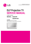
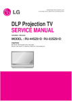
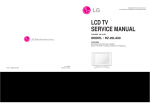
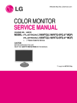
website:http://biz.LGservice.com
e-mail:http://www.LGEservice.com/techsup.html
DLP PROJECTOR
SERVICE MANUAL
CHASSIS : RE-048A
MODEL : RD-JT91
CAUTION
BEFORE SERVICING THE CHASSIS,
READ THE SAFETY PRECAUTIONS IN THIS MANUAL.
CONTENTS
CONTENTS .......................................................................................................................2
SAFETY PRECAUTIONS .................................................................................................3
SERVICING PRECAUTIONS............................................................................................4
CONTROL DESCRIPTIONS .............................................................................................6
REPLACING OF LAMP ..................................................................................................10
SPECIFICATIONS ...........................................................................................................11
ADJUSTMENT INSTRUCTION.......................................................................................13
PRINTED CIRCUIT BOARD ...........................................................................................18
BLOCK DIAGRAM..........................................................................................................21
EXPLODED VIEW...........................................................................................................22
EXPLODED VIEW PARTS LIST .....................................................................................23
REPLACEMENT PARTS LIST........................................................................................24
SVC. SHEET .......................................................................................................................
- 2 -
SAFETY PRECAUTIONS
IMPORTANT SAFETY NOTICE
Many electrical and mechanical parts in this chassis have special safety-related characteristics. These parts are identified by
in
the Schematic Diagram and Replacement Parts List.
It is essential that these special safety parts should be replaced with the same components as recommended in this manual to
prevent X-RADIATION, Shock, Fire, or other Hazards.
Do not modify the original design without permission of manufacturer.
General Guidance
Before returning the receiver to the customer,
An isolation Transformer should always be used during
the servicing of a receiver whose chassis is not isolated from
the AC power line. Use a transformer of adequate power rating
as this protects the technician from accidents resulting in
personal injury from electrical shocks.
always perform an AC leakage current check on the exposed
metallic parts of the cabinet, such as antennas, terminals, etc.,
to be sure the set is safe to operate without damage of
electrical shock.
Leakage Current Cold Check(Antenna Cold Check)
It will also protect the receiver and it's components from being
damaged by accidental shorts of the circuitry that may be
inadvertently introduced during the service operation.
If any fuse (or Fusible Resistor) in this TV receiver is blown,
replace it with the specified.
When replacing a high wattage resistor (Oxide Metal Film
Resistor, over 1W), keep the resistor 10mm away from PCB.
Keep wires away from high voltage or high temperature parts.
Due to high vacuum and large surface area of picture tube,
extreme care should be used in handling the Picture Tube.
Do not lift the Picture tube by it's Neck.
X-RAY Radiation
Warning:
The source of X-RAY RADIATION in this TV receiver is the
High Voltage Section and the Picture Tube.
For continued X-RAY RADIATION protection, the
replacement tube must be the same type tube as specified in
the Replacement Parts List.
To determine the presence of high voltage, use an accurate
high impedance HV meter.
With the instrument AC plug removed from AC source,
connect an electrical jumper across the two AC plug prongs.
Place the AC switch in the on position, connect one lead of
ohm-meter to the AC plug prongs tied together and touch other
ohm-meter lead in turn to each exposed metallic parts such as
antenna terminals, phone jacks, etc.
If the exposed metallic part has a return path to the chassis, the
measured resistance should be between 1MΩ and 5.2MΩ.
When the exposed metal has no return path to the chassis the
reading must be infinite.
An other abnormality exists that must be corrected before the
receiver is returned to the customer.
Leakage Current Hot Check (See below Figure)
Plug the AC cord directly into the AC outlet.
Do not use a line Isolation Transformer during this check.
Connect 1.5K/10watt resistor in parallel with a 0.15uF capacitor
between a known good earth ground (Water Pipe, Conduit, etc.)
and the exposed metallic parts.
Measure the AC voltage across the resistor using AC
voltmeter with 1000 ohms/volt or more sensitivity.
Reverse plug the AC cord into the AC outlet and repeat AC
voltage measurements for each exposed metallic part. Any
voltage measured must not exceed 0.75 volt RMS which is
corresponds to 0.5mA.
In case any measurement is out of the limits specified, there is
possibility of shock hazard and the set must be checked and
repaired before it is returned to the customer.
Leakage Current Hot Check circuit
Adjust brightness, color, contrast controls to minimum.
Measure the high voltage.
The meter reading should indicate
23.5 ¡ 1.5KV: 14-19 inch, 26 ¡ 1.5KV: 19-21 inch,
29.0 ¡ 1.5KV: 25-29 inch, 30.0 ¡ 1.5KV: 32 inch
If the meter indication is out of tolerance, immediate service
and correction is required to prevent the possibility of
premature component failure.
AC Volt-meter
To Instrument's
exposed
METALLIC PARTS
0.15uF
1.5 Kohm/10W
- 3 -
Good Earth Ground
such as WATER PIPE,
CONDUIT etc.
SERVICING PRECAUTIONS
CAUTION: Before servicing receivers covered by this service
manual and its supplements and addenda, read and follow the
SAFETY PRECAUTIONS on page 3 of this publication.
NOTE: If unforeseen circumstances create conflict between the
following servicing precautions and any of the safety
precautions on page 3 of this publication, always follow the
safety precautions. Remember: Safety First.
General Servicing Precautions
1. Always unplug the receiver AC power cord from the AC
power source before;
a. Removing or reinstalling any component, circuit board
module or any other receiver assembly.
b. Disconnecting or reconnecting any receiver electrical plug
or other electrical connection.
c. Connecting a test substitute in parallel with an electrolytic
capacitor in the receiver.
CAUTION: A wrong part substitution or incorrect
polarity installation of electrolytic capacitors may result
in an explosion hazard.
d. Discharging the picture tube anode.
2. Test high voltage only by measuring it with an appropriate
high voltage meter or other voltage measuring device (DVM,
FETVOM, etc) equipped with a suitable high voltage probe.
Do not test high voltage by "drawing an arc".
3. Discharge the picture tube anode only by (a) first connecting
one end of an insulated clip lead to the degaussing or kine
aquadag grounding system shield at the point where the
picture tube socket ground lead is connected, and then (b)
touch the other end of the insulated clip lead to the picture
tube anode button, using an insulating handle to avoid
personal contact with high voltage.
4. Do not spray chemicals on or near this receiver or any of its
assemblies.
5. Unless specified otherwise in this service manual, clean
electrical contacts only by applying the following mixture to
the contacts with a pipe cleaner, cotton-tipped stick or
comparable non-abrasive applicator; 10% (by volume)
Acetone and 90% (by volume) isopropyl alcohol (90%-99%
strength)
CAUTION: This is a flammable mixture.
Unless specified otherwise in this service manual, lubrication
of contacts in not required.
6. Do not defeat any plug/socket B+ voltage interlocks with
which receivers covered by this service manual might be
equipped.
7. Do not apply AC power to this instrument and/or any of its
electrical assemblies unless all solid-state device heat sinks
are correctly installed.
8. Always connect the test receiver ground lead to the
receiver chassis ground before connecting the test receiver
positive lead.
Always remove the test receiver ground lead last.
9. Use with this receiver only the test fixtures specified in this
service manual.
CAUTION: Do not connect the test fixture ground strap to
any heatsink in this receiver.
Electrostatically Sensitive (ES) Devices
Some semiconductor (solid state) devices can be damaged
easily by static electricity. Such components commonly are
called Electrostatically Sensitive (ES) Devices. Examples of
typical ES devices are integrated circuits and some field-effect
transistors and semiconductor "chip" components. The
following techniques should be used to help reduce the
incidence of component damage caused by static by static
electricity.
1. Immediately before handling any semiconductor component
or semiconductor-equipped assembly, drain off any
electrostatic charge on your body by touching a known earth
ground. Alternatively, obtain and wear a commercially
available discharging wrist strap device, which should be
removed to prevent potential shock reasons prior to
applying power to the unit under test.
2. After removing an electrical assembly equipped with ES
devices, place the assembly on a conductive surface such as
aluminum foil, to prevent electrostatic charge buildup or
exposure of the assembly.
3. Use only a grounded-tip soldering iron to solder or unsolder
ES devices.
4. Use only an anti-static type solder removal device. Some
solder removal devices not classified as "anti-static" can
generate electrical charges sufficient to damage ES devices.
5. Do not use freon-propelled chemicals. These can generate
electrical charges sufficient to damage ES devices.
6. Do not remove a replacement ES device from its protective
package until immediately before you are ready to install it.
(Most replacement ES devices are packaged with leads
electrically shorted together by conductive foam, aluminum
foil or comparable conductive material).
7. Immediately before removing the protective material from
the ieads of a replacement ES device, touch the protective
material to the chassis or circuit assembly into which the
device will be installed.
CAUTION:Be sure no power is applied to the chassis or
circuit, and observe all other safety precautions.
8. Minimize bodily motions when handling unpackaged
replacement ES devices. (Otherwise harmless motion such
as the brushing together of your clothes fabric or the lifting
of your foot from a carpeted floor can generate static
electricity sufficient to damage an ES device.)
General Soldering Guidelines
1. Use a grounded-tip, low-wattage soldering iron and
appropriate tip size and shape that will maintain tip
temperature within the range or 500¡£
F to 600¡£
F.
2. Use an appropriate gauge of RMA resin-core solder
composed of 60 parts tin/40 parts lead.
3. Keep the soldering iron tip clean and well tinned.
4. Throughly clean the surfaces to be soldered. Use a mall
wirebristle (0.5 inch, or 1.25cm) brush with a metal handle.
Do not use freon-propelled spray-on cleaners.
5. Use the following unsoldering technique
a. Allow the soldering iron tip to reach normal temperature.
(500¡£
F to 600¡£
F)
b. Heat the component lead until the solder melts.
c. Quickly draw the melted solder with an anti-static,
suction-type solder removal device or with solder braid.
CAUTION: Work quickly to avoid overheating the circuitboard printed foil.
6. Use the following soldering technique.
a. Allow the soldering iron tip to reach a normal
temperature (500¡£
F to 600¡£
F)
b. First, hold the soldering iron tip and solder the strand
against the component lead until the solder melts.
- 4 -
c. Quickly move the soldering iron tip to the junction of the
component lead and the printed circuit foil, and hold it
there only until the solder flows onto and around both the
component lead and the foil.
CAUTION: Work quickly to avoid overheating the circuit
board printed foil.
d. Closely inspect the solder area and remove any excess
or splashed solder with a small wire-bristle brush.
IC Remove/Replacement
Some chassis circuit boards have slotted holes (oblong) through
which the IC leads are inserted and then bent flat against the
circuit foil. When holes are the slotted type, the following
technique should be used to remove and replace the IC. When
working with boards using the familiar round hole, use the
standard technique as outlined in paragraphs 5 and 6 above.
Removal
1. Desolder and straighten each IC lead in one operation by
gently prying up on the lead with the soldering iron tip as the
solder melts.
2. Draw away the melted solder with an anti-static suctiontype solder removal device (or with solder braid) before
removing the IC.
Replacement
1. Carefully insert the replacement IC in the circuit board.
2. Carefully bend each IC lead against the circuit foil pad and
solder it.
3. Clean the soldered areas with a small wire-bristle brush.
(It is not necessary to reapply acrylic coating to the areas).
"Small-Signal" Discrete Transistor
Removal/Replacement
1. Remove the defective transistor by clipping its leads as
close as possible to the component body.
2. Bend into a "U" shape the end of each of three leads
remaining on the circuit board.
3. Bend into a "U" shape the replacement transistor leads.
4. Connect the replacement transistor leads to the
corresponding leads extending from the circuit board and
crimp the "U" with long nose pliers to insure metal to metal
contact then solder each connection.
Power Output, Transistor Device
Removal/Replacement
1. Heat and remove all solder from around the transistor leads.
2. Remove the heatsink mounting screw (if so equipped).
3. Carefully remove the transistor from the heat sink of the
circuit board.
4. Insert new transistor in the circuit board.
5. Solder each transistor lead, and clip off excess lead.
6. Replace heatsink.
Diode Removal/Replacement
1. Remove defective diode by clipping its leads as close as
possible to diode body.
2. Bend the two remaining leads perpendicular y to the circuit
board.
3. Observing diode polarity, wrap each lead of the new diode
around the corresponding lead on the circuit board.
4. Securely crimp each connection and solder it.
5. Inspect (on the circuit board copper side) the solder joints of
the two "original" leads. If they are not shiny, reheat them
and if necessary, apply additional solder.
Fuse and Conventional Resistor
Removal/Replacement
1. Clip each fuse or resistor lead at top of the circuit board
hollow stake.
2. Securely crimp the leads of replacement component around
notch at stake top.
3. Solder the connections.
CAUTION: Maintain original spacing between the replaced
component and adjacent components and the circuit board
to prevent excessive component temperatures.
Circuit Board Foil Repair
Excessive heat applied to the copper foil of any printed circuit
board will weaken the adhesive that bonds the foil to the circuit
board causing the foil to separate from or "lift-off" the board.
The following guidelines and procedures should be followed
whenever this condition is encountered.
At IC Connections
To repair a defective copper pattern at IC connections use the
following procedure to install a jumper wire on the copper
pattern side of the circuit board. (Use this technique only on IC
connections).
1. Carefully remove the damaged copper pattern with a sharp
knife. (Remove only as much copper as absolutely
necessary).
2. carefully scratch away the solder resist and acrylic coating
(if used) from the end of the remaining copper pattern.
3. Bend a small "U" in one end of a small gauge jumper wire and
carefully crimp it around the IC pin. Solder the IC connection.
4. Route the jumper wire along the path of the out-away
copper pattern and let it overlap the previously scraped end
of the good copper pattern. Solder the overlapped area and
clip off any excess jumper wire.
At Other Connections
Use the following technique to repair the defective copper
pattern at connections other than IC Pins. This technique
involves the installation of a jumper wire on the component
side of the circuit board.
1. Remove the defective copper pattern with a sharp knife.
Remove at least 1/4 inch of copper, to ensure that a
hazardous condition will not exist if the jumper wire opens.
2. Trace along the copper pattern from both sides of the
pattern break and locate the nearest component that is
directly connected to the affected copper pattern.
3. Connect insulated 20-gauge jumper wire from the lead of
the nearest component on one side of the pattern break to
the lead of the nearest component on the other side.
Carefully crimp and solder the connections.
CAUTION: Be sure the insulated jumper wire is dressed so
the it does not touch components or sharp edges.
- 5 -
CONTROL DESCRIPTIONS
Names of parts
Main Body
* The projector is manufactured using high-precision technology. You may, however, see on the Projector
screen tiny black points and/or bright points (red, blue, or green). This can be a normal result of the
manufacturing process and does not always indicate a malfunction.
Rear remote control sensor
Zoom ring
Control panel
Focus ring
Power button
Indicators
Foot adjusting button
PO
O
AUT
WE
R
VOL
MEN
OK
U
VOL
SOU
RCE
Front remote control sensor
Lens cover
* Push the lens cover into the inside after pulling it open into the
front. (If you mount on the ceiling, after pushing the cover, the lens
cover is installed. If not, the cover may overlap projecting lens.)
Foot adjusting button
Connecting Part
USB(Service)
DVI Input
Audio
S-Video
RGB Input
(PC/DTV)
*This jack is only used for service.
Video
AC IN
Kensington Security
System Connector
- 6 -
Control Panel
/
, KEYSTONE+/- Button
SOURCE
MENU
KEYSTONE
MENU Button
SOURCE Button
Selects or closes menus.
Switches to RGB, DVI, Video,S-Video mode.
VOL
VOL
VOLUME Button
Adjusts volume level and
functions of menus.
AUTO Button
AUTO
A
KEYSTONE
OK
POWER Button
POWER
- 7 -
OK Button
Checks present mode and
saves the change of functions.
Remote Control
POWER
POWER Button
MENU
KEYSTONE
SOURCE
SOURCE Button
MENU Button
VOL-/+,
F
/
GButton
VOL
VOL
AUTO Button
A
AUTO
KEYSTONE
OK Button
OK
ARC Button
BLANK Button
BLANK
ARC
MUTE
STILL
STILL Button
MUTE Button
*Switches the sound on or off.
KEYSTONE+/-,
- 8 -
D
/
EButton
Projector Status Indicators
* Lamp Indicator, operation indicator and temperature indicator at the top of the projector show the user the operating
status of the projector.
Lamp Indicator
Operation Indicator Temperature Indicator
PO
AU
VO
ME
WE
R
TO
L
OK
NU
VO
SO
UR
L
CE
Operation Indicator
Orange
Green(flashing)
Green
Orange(flashing)
Off
Red
Lamp Indicator
Red(flashing)
Green(flashing)
Orange
Temperature Indicator Red
Red (flashing)
Standby.
The fan is running while the lamp preheats.
The lamp is preheated and on.
Projector lamp is cooling as power out (2 minutes)
Power off.
Projector lamp is reaching the end of its life and needs
to be replaced with a new lamp. (over 2000 hours)
The projector has trouble in the lamp or around it at
power-on. Retry Power On again later. If lamp indicator
is red (flashing) again, contact the service center.
The lamp cover is not closed.
The projector is in a high temperature condition. Turn off
the power to the unit and check for proper ventilation.
The projector is turned off due to the unit overheating.
Power has turned off due to problem with the
internal cooling fan. The fan is not operating.
- 9 -
REPLACING OF LAMP
The projector lamp should lasts for about 2000 hours.You can
see the lamp hours time in the selecting function section.You
must replace the lamp when one or more of the following
apply.
4. After lifting the lamp cover off, remove the two retaining
screws on the lamp case with a screwdriver.
5. Lift up the fixed wire handle of the lamp.
The projected image gets darker or starts to become
distorted.
O The lamp indicator is red.(Red,flashing alternately)
O The message “ LAMP REPLACE” appears on the screen
when turning the projector lamp on.
O
1. Turn off the projector and unplug the power cable.
(allow the lamp to cool for more than 1 hour.)
6. Pull out the handle slowly and remove the lamp case.
7. Insert the new lamp gently into the correct position. Make
sure it is inserted correctly.
8. Tighten the screws you removed in step 4.
2. Stand the projector on its side as below so that you can
easily access the lamp cover.
3. Remove the two retaining screws on the lamp cover with a
screwdriver and then lift off the lamp cover.
9. Replace the lamp cover and tighten the cover screws.
(Make sure the lamp cover is securely fastened.
If the lamp cover is open, the lamp indicator flashes green
and the projector will not turn on.)
Bottom of the Projector
- 10 -
SPECIFICATIONS
NOTE : Specifications and others are subject to change without notice for improvement.
A
Scope
This standard can be applied to the LCD Projector related to RE-048A Chassis.
A
Test Condition
1) Temperature : 25°C¡ 5°C (Only CST is 40°C¡ 2°C )
2) Relative Humidity: 65¡ 10%
3) Power Voltage: Standard input voltage (AC 100 - 240V, 50/60Hz)
4) Use the parts only designated in B.O.M.,PARTS SPEC.,or drawings.
5) Follow each drawing or spec for spec and performance of parts,based upon P/N of B.O.M
6) Warm up TV set for more than 30min. before the measurement.
A
Test and Inspection Method
1) performance:Follow the Standard of LG TV test
2) RCA JACK performance: Follow the standard of LG
3) Standards of Etc requirement
SAFETY:CE (EN55020), Electric wave:CB (EN55013)
A
General Specification
Specification
No.
Item
Remark
Min
1
Video input applicable system
Typ
Max
Unit
NTSC M
3.579545 / 60Hz
NTSC 4.43
4.433618 / 60Hz
PAL
4.433618 / 50Hz
PAL M
3.575611 / 60Hz
PAL N
3.582056 / 50Hz
SECAM
4.286 / 50Hz
NTSC-PB
4.433618 / 60Hz
2
Power
SMPS
3
Input Voltage
AC 100(-10%) - 240(+6%)V,50/60Hz
4
Market
World wide
5
Screen size
4:3 / 16:9
6
Aspect ratio
4:3
7
Operating Temperature
0
8
Operating Humidity
9
Storage Temperature
10
Storage Humidity
-20
- 11 -
40
deg
85
%
60
deg
85
%
A
Feature and function
Specification
No.
Item
Remark
Min
Typ
Max
Unit
1
REMOCON
NEC Code
2
DVI Input
1
Digital RGB
DVI-D
3
RGB Input
1
Separate
D-Sub 15 pin
4
Component input
1
Y, PB, PR
D-Sub 15 pin
480i, 480p, 720p, 1080i, 576i,576p
5
Composite input
1
480i, 576i
RCA jack(Yellow)
6
S-video input
1
480i,576i
S-VIDEO jack
7
Audio input
1
PC-audio jack
8
USB Port
1
USB jack (only for download)
9
Local Key
Power, Menu, OK, Vol(+,-)
Source, keystone+/ keystone, auto
10
Picture, Gamma
Normal/ Film/ Sports
11
Picture, User Control
Contrast/ Brightness/ Color/ Tint/ Sharpness
12
ACC
Normal/ Warm/ Cool
13
Display mode
4:3 / 16:9
14
Sound
1W mono
15
OSD Language
Korean/ english/ Deutsch/ Italiano/ Espanol
/ Chinese/ Japanese/ france/ Swedish
- 12 -
ADJUSTMENT INSTRUCTION
1. Application Object
4. Folding Mirror Adjustment
This instruction is for the application to the DLP Projector
(CHASSIS : RE-048A).
4-1. Before adjusting, check the position of
Folding MIrror
2. Notes
Check the position of Folding Mirror in the base of up /
down / left / right surface. (Fig. 4-1)
(1) The power source insulation of this DLP Projector is not
charging type and you may not use the transformer for
insulation. It is advised to use an insulation transform
between the power supply cable and power input of the set
to protect the test equipment.
(2) The adjustment must be performed under the correct
sequence.
(3) The adjustment must be performed in the circumstance of
25!5cC of temperature and 65!10% of relative humidity.
(4) The input voltage of the receiver must keep AC 110V,
60Hz during adjustment.
(5) The set must be on for 5 minutes prior to any adjustment.
After receiving possible 100% white pattern, it is operated
preliminarily.
(1) Check the Lower Position
As shown <Fig. 4-1>, check the mirrors lower position in the
middle of the hole, located under the holder.
3. Accessing the Adjustment Mode
hole of the lower holder
(1) Pressing the instart key on the service remote will open or
close the service menu.
(2) As shown <Fig. 1>, use the (CH+ (D),CH- (E)), select to
item press the ENTER or VOLUME key to enter the item
you wish to adjust.
1. Test Pattern
G
2. Optic Check
G
<Fig.4-1> Check the Lower Position of Folding Mirror
(2) Check the Left / Right Position
After checking the lower position, as shown <Fig. 4-2>, fix the
sides so they are vertically aligned with the base surface.
3. Temperature
4. RGB Gain/Off Set
5. Component Gain/Off Set
6. White Balance
7. CWI
8. Lamp Time Reset
base surface
9. White Peaking
<Fig.4-2> Check the Left / Right Position of Folding Mirror
10. PWM
<Fig.3> OSD of Adjustment Mode
Top and bottom
adjustment screw A
(3) Press the Instart key to exit the service menu.
(4) Preparation for Adjustment
1) Power is connected in set to be power on.
2) Do heat run 5minutes.
Left and right
adjustment screw B
Left and right
adjustment screw C
<Fig.4-3> Illuminator Adjustment Part by Folding Mirror
- 13 -
(4) Final Adjustment
4-2. Illuminator Adjustment Sequence
Check the full white screen refer to (Fig 4-3) and make
adjustments in the following sequence.
(1) Up and Down Adjustment
1) Mark screw (A) in its original position. Turn screw (A) up /
down adjustment to the left and mark where the image is
aligned.
2) Mark screw (A) in its original position. Turn screw (A) up /
down adjustment to the right and mark where the image is
aligned.
3) Turn screw (A) up / down adjustment to the right / left and
mark where the image is aligned. Fix the adjustment screw
in position.
Step 1
Step 2
Step 3
<Fig.4-4> Illuminator up / down Adjustment Sequence
(2) Left and Right Adjustment 1
1) Mark screw (B) in its original position. Turn screw (B) Left /
Right adjustment to the right and mark where the image is
aligned.
2) Mark screw (B) in its original position. Turn screw (B) Left /
Right adjustment to the left and mark where the image is
aligned.
3) Turn screw (B) Left / Right adjustment to the right / left and
mark where the image is aligned. Fix the adjustment screw
in position.
Step 1
Step 2
Step 3
<Fig.4-5> Illuminator Left/Right Adjustment Sequence 1
(3) Left and Right Adjustment 2
1) Mark screw (C) in its original position. Turn screw (C) up /
down adjustment to the right and mark where the image is
aligned.
2) Mark screw (C) in its original position. Turn screw (C) up /
down adjustment to the left and mark where the image is
aligned.
3) Turn screw (C) up / down adjustment to the right / left and
mark where the image is aligned. Fix the adjustment screw
in position.
Step 1
Step 2
Step 3
<Fig.4-6> Illuminator Left/Right Adjustment Sequence 2
- 14 -
Repeat turn screw (C) up / down adjustment to the right / left
and mark where the image is aligned. Fix the adjustment
screw in position. 1), 2), 3) adjustment twice and find the
optimum position. Check the image with the naked eye for
optimum alignment.
4-3. Illuminator Phenomenon Adjustment
Illuminator goes down direction
Adjustmen
t part
Screw
direction
Illuminator goes down area
Screen state
Description
Initial state
State after adjusting
Right
(tighten
direction)
At first, upside illuminator goes down
and right illuminator also goes down in
detail.
Left
(loosen
direction)
At first, downside illuminator goes
down and left illuminator also goes
down.
Right
(tighten
direction)
At first, left illuminator goes down and
downside illuminator also goes down.
Left
(loosen
direction)
At first, right illuminator goes down and
upside illuminator also goes down.
Right
(tighten
direction)
At first, left illuminator goes down and
downside illuminator also goes down.
Left
(loosen
direction)
At first, right illuminator goes down and
upside illuminator also goes down.
Up/down
screw A
left/right
screw B
left/right
screw C
5-2. Caution for DMD Clean
5. Caution for DMD
(Digital Micro-mirror Device)
5-1. Caution for DMD ESD
(1) Connector the grounding to prevent a damage of ESD
(Electrostatic Discharge) when handing the DMD.
(2) Wear a wrist strap to connect the ESD grounding in flesh
necessarily.
(3) Connect the ESD ground to workstation and an electric
conductor.
(4) Save the DMD after getting rid of a static electricity. Keep
it at an exclusive case when moving it When grounding,
open the case.
(5) Put on gloves for preventing static electricity.
(6) All work is done at static free location. Attach the tape or
remove a dust on the DMD front or DMD back pin
- 15 -
(1) Follow the procedure and caution to prevent the screen
from being scratched.
(2) When DMD glass stains with dust, polish the front and
back DMD glass with soft cloth. Then, do it again after
rotating 180 degree the DMD. If necessary, keep under
observation.
(3) Don’t clean the DMD with the high pressure. The static
electricity and pressure will damage the DMD.
6. RGB Offset/Gain Adjustment
7. COMPONENT Offset/Gain Adjustment
(1) Select 75% color bar of <Fig. 7> for PC Pattern Generator
pattern. (Resolution 480p)
6-1. Required Test Equipment
(1) Pattern Generator 1EA (For analog RGB)
(2) Remote control 1EA
6-2. Setting of the device
Set the equipment as <Fig. 6-1>.
SCREEN
Projector
RGB
PC Pattern
Generator
<Fig.6-1> Device setting diagram for RGB offset/gain adjustment
<Fig. 7>
6-3. Preparation for Adjustment
(1) Connect the pattern generator as <Fig. 6-1>.
(2) Adjust pattern generator to SVGA 60Hz.
(3) Press the Input selection button to select the RGB input.
(2) Press the instart button on the remote control to select
component offset/gain set in the adjustment menu.
(3) Automatic Adjustment : Press the enter button in
component offset/gain set of Adjustment menu.
(Adjustment is operated by system Micom automatically)
6-4. Sequence of Adjustment
(1) Select the white/back pattern for pattern generator as
<Fig. 6-2>. (SVGA 60Hz)
[. CWI/White Balance Measurement
Condition
(1) CWI and White Balance is adjusted using a CL-200 or
equivalent.
(2) Adjust the screen size to a minimum of 40 inches.
(3) Place the CL-200 on the center of projection screen.
(4) Make the measurement condition under 1Lux for CL-200
to measure the correct color coordinate.
8. CWI Adjustment
<Fig.6-2> Window Pattern
(2) Press the instart button on the service remote control to
select RGB offset/gain set in Adjustment menu.
(3) Automatic Adjustment : Press the enter button in RGB
offset/gain set of Adjustment menu. (Adjustment is
operated by system Micom automatically)
8-1. Setting of the Device
Set the equipment as <Fig. 8-1>.
Illuminometer
Equipment to monitor Lx,X,Y data
Set
SCREEN
PC input
(Computer of Pattern)
Set fixing device
<Fig.8-1> Device setting diagram for CWI adjustment
8-2 Required Test Equipment
(1) Illuminometer (Model : CL-200) 1EA : Chromaticity
measurement from projection screen center.
(2) PC input equipment (Pattern Generator, PC)
(3) Set fixing device 1EA
(4) Remote control 1EA
- 16 -
8-3. Preparation for Adjustment
(1) Connect the power cord and turn the set on, then connect
it to a PC input.
(2) Enter the CWI menu by using the Instart key on the
service remote. (Default value : 268)
(3) When entering CWI, a full red screen will display. At this
time, see the Illuminometer color coordinates on the
center.
(4) Press the Instart key on the service remote control to
select White balance.
(5) Change X, Y as below seeing X and Y coordinate of
illuminometer data.
1) Standard color coordinate when adjusting Warm
(6500!200 degree) mode
: X=0.313!0.002, Y=0.329!0.002
- Adjust the white X,Y
(default : white X -> 9995, white Y -> 10992)
2) Standard color coordinate when adjusting Cool
(9300!200 degree) mode
: X=0.283!0.002, Y=0.297!0.002)
- Adjust the white Y
(default : white X -> 9995, white Y -> 10992)
[ It is unnecessary for normal mode adjustment.(The
remote control data does not become input)
(6) Press the Instart key on the service remote to select white
balance again and check the adjusted state of warm and
cool. Then, select normal and exit the service menu.
<Fig.8-2> TEST pattern (RED pattern)
8-4. Sequence of Adjustment
(1) Adjust CWI to the left/right value by using the volume
buttons at the first adjustment value is preset to 268.
(2) Illuminometer color coordinates change when pressing
volume button.
(3) X coordinates usually get maximum value at
X=0.630!0.02 and Y coordinates usually get minimum
value at Y=0.350!0.02. Adjust this value by pressing
volume button on the remote control. Adjustment range is
usually 258~278 and average value is 268.
(4) Check the red pattern whether it is entirely uniform. If it is
uniform then this setting is OK.
9. White Balance Adjustment
9-1. Required Test Equipment
(1) Illuminometer (Model : CL-200) 1EA : Chromaticity
measurement from projection screen center
(2) Pattern Generator (DVI input)
(3) Set fixing device 1EA
(4) Remote control 1EA
9-2. Equipment Composition
(1) Compose the equipment as <Fig. 9>.
Illuminometer
Equipment to monitor Lx,X,Y data
Set
SCREEN
Pattern generator
White 70% input
Set fixing device
<Fig.9> Equipment composition Diagram
(2) It may use a pattern other than 70% white. Use a white
pattern.
(3) Press the Instart key on the service remote to select white
peaking and check the RGB/DVI peaking data should be
set to 10.
- 17 -
PRINTED CIRCUIT BOARD
MAIN(TOP)
- 18 -
MAIN(BOTTOM)
- 19 -
DMD(TOP)
DMD(BOTTOM)
- 20 -
- 21 -
C o m p -In
AD 9 8 8 3
101 ~ 199
301 ~ 399
U SB
IR re m o t e
Ke y p a d
Y/ C
C VB S
D S UB
SI L 1 6 9
VPC3230
D VI
201 ~ 299
Y/ C- Out
CW
Driver
16
24
D RC G
501 ~ 599
16
16
CW Drive
CW Ind ex
8
64
RD R A M
401 ~ 499
D D P2 0 0 0
5 6 4 PB G A
21
F RO M /
S D RA M
D AD 1 0 0 0
/ Re s e t
16
D MD
IF
701 ~ 749
So u n d
D MD
IF
D MD
0. 55"
S VG A
750 ~ 799
TPA0 2 4 2
601 ~ 699
So u n d Pa r t
BLOCK DIAGRAM
EXPLODED VIEW
1
4
2
3
5
6
7
8
10
9
11
12
13
14
15
21
20
19
17
26
39
40
67
30
25
35
34
69
70
16
68
29
53
38
23
IC753
18
37
33
71
36
28
32
22
27
24
58
57
54
41
43
62
55
61
74
56
42
59
63
74
60
64
66
44
65
45
51
50
52
46
49
47
48
- 22 -
EXPLODED VIEW PARTS LIST
No.
Part No.
1
2
3
4
5
6
7
8
9
10
11
12
13
14
15
16
17
18
19
20
21
22
23
24
25
26
27
28
29
30
32
33
34
35
36
37
38
39
40
41
42
43
44
45
46
47
48
49
50
51
52
53
54
55
56
57
58
59
60
61
62
63
64
65
66
67
68
69
70
71
74
4850V00119A
4850V00118A
4930V00404B
3720V00264B
4810V01028A
3550V00465C
3520V00415A
3520V00435A
3550V00482A
5020V00941B
4810V01051A
4810V01032A
3790V00762A
3141VMNS56A
3581V00041A
4810V01054A
4810V01053A
6912B22008A
3550V00468A
4810V01039A
4810V01038A
4970V00065B
4930V00393A
4814V00469B
3550V00466B
3550V00467B
4810V01026A
3680V00129A
4814V00474B
4814V00472B
4814V00473B
6871VSMZ47A
3300V00354B
4970V00066B
4920V00145B
4930V00395B
5900V05005A
3550V00469A
3550V00470A
5900V08011A
4810V01044B
4972V00125B
4810V01049A
3550V00472B
3550V00505A
3580V00107B
4810V01040A
4778V00068C
3110V00404A
4778V00109A
3530V00153C
4930V00397A
6400TG0004B
4980V01096B
4972V00125A
4810V01052B
5900V08011B
4980V00B24A
6316000008A
3858V00070A
4980V01097D
3501V00196C
4980V01097C
3501V00196E
4980V01097E
5230V00023A
6871VSMZ48A
3141VSNF28A
4810V01031A
4970V00067B
6871VSMZ50C
Description
CUSHION, SPONGE 75*40*12.5 SPONGE RD-JT91
CUSHION, SPONGE 75*59*19.5 SPONGE RD-JT91
HOLDER, SPONGE SUS304 T0.3 RD-JT91
PANEL, CONTROL RD-JT92 ACRYL STS PLATING
BRACKET, TOP RD-JT91 RE03RA PC LENS
COVER, TOP RD-JT91 MG MASKING
INDICATOR, LED RD-JT91 PMMA 3 LIGHT
INDICATOR, PRE AMP RD-JT91 PMMA FRONT
COVER, RD-JT91 PC LENS
BUTTON, CONTROL RD-JT91 ABS, AF-303S 4KEY ASSY
BRACKET, DECO RD-JT91 RE03RA PC-ABS SIDE REAR
BRACKET, CASE RD-JT91 RE03RA PC-ABS SIDE REAR
WINDOW, PRE-AMP RD-JT91 PC REAR
CHASSIS ASSEMBLY, MAIN RE048A MAIN PCB
DOOR ASSEMBLY, ASSY RD-JT91 DOOR
BRACKET, RD-JT91 RE03RA LCP+GF30%
BRACKET, RD-JD91 RE03RA LCP+GF30%
LAMP,HIGH PRESSURE MECURY NSH200LGA USHIO 82V 2.4A 200W PROJECTOR
COVER, LAMP RD-JT91
BRACKET, COVER RD-JT91 PC-ABS BRACKET LOUVER INLET
BRACKET, COVER RD-JT91 PC-ABS LOUVER_EXIT
SPRING, PLATE SUS LAMP COVER
HOLDER, LAMP LCP+GF30 RD-JT91
SHIELD, PLATE RD-JT91 RE048A AL
COVER, TOP CASE COVER AL RD-JT91
COVER, TOP RD-JT91 AL C/W
BRACKET, FIXER OPTICAL CASE RD-JT91 RE048A MG
LENS, COSINA LENS RD-JT91 .
SHIELD, DMD BT RE048A AL RD-JT91
SHIELD, DMD UPPER RE048A AL RD-JT91
SHIELD, DMD LEFT RE048A AL RD-JT91
PWB(PCB) ASSEMBLY,SUB DMD RE048A DMD
PLATE, SHIELD AL RD-JT91
SPRING, PLATE STSC304 RD-JT91
HEAT SINK, EXTRUSION 65*68 RD-JT91
HOLDER, BLOWER SECC RD-JT91
FAN,DC A34860-58LG NIDEC 51MM*51MM*15MM 12V 3700RPM 7.0V - 13.8V RD-JT91 LAMP BULB COOLING FAN
COVER, FAN BLOWER RD-JT91 PC
COVER, DUCT RD-JT91 PEEK
FAN,DC 8412N/2GME PAPST 80*80*25.4MM 12V 2600RPM 8V - 15V RD-JT91 LAMP COOLING FAN
BRACKET, DUCT LAMP FAN RD-JT91 RE048A SECC(EGI)
FIXER, POLYURETHAN FANMOUNT RD-JT91 YELLOEW
BRACKET, DUCT RD-JT91 RE03RA PC-ABS BLOW DIR
COVER, LAMP RD-JT91 SECC(EGI) PRESS
COVER, FRONT RD-JT91 PC GF35% BK
DOOR, RD-JT92 PC LENS FRONT
BRACKET, COVER RD-JT91 PC-ABS DOOR BOX
LEG, ASSY RD-JT91 ABS, HF-380 FOR LEG”
CASE, BOTTOM RD-JT91 MG WAFFER
LEG, RUBBER RD-JT91 POLYURETHAN REAR
GRILLE, SHEET RD-JT91 EGI 2.8 HOLE PRESS
HOLDER, SENSOR BOARD MOUNT PC+GF30 RD-JT91
SPEAKER,TWEETER T028S01K1454 ESTEC 8OHM 1.0/1.5W 78DB OTHERS D28*5.6MM WIRE 300MM FROM 6400TG0004A
SUPPORTER, SPEAKER SUS RD-JT91
FIXER, POLYURETHAN FANMOUNT RD-JT91 BLUE
BRACKET, SHIELD RD-JT91 RE048A SUS .
FAN,DC 8412N/2GMLE PAPST 80*80*25.4MM 12V 2050RPM 8V - 15V RD-JT91 POWER BOARD COOLING FAN
SUPPORTER, PC-ABS BRACKET BALLASTER SUP
BALLAST, PHG161G7KM USHIO 200W PROJECTOR
SHEET (MECH), PVC MAIN . SHIELD
SUPPORTER, PCB MSWR RD-JT91
POWER SUPPLY ASSEMBLY, POWER RD-JT91 RE048A PV-JT91 POWER VALLEY SMPS BOARD 100_240V . POWERVALLEY .
SUPPORTER, PCB MSWR RD-JT91
POWER SUPPLY ASSEMBLY, POWER RD-JT91 RE048A POWER VALLEY PFC BOARD 100_240V . POWERVALLEY .
SUPPORTER, PCB MSWR NICKLE PLATING RD-JT91
FILTER(MECH), COLOR WHEEL RD-JT91 .
PWB(PCB) ASSEMBLY,SUB, CW-INDEX RE048A CW_INDEX
CHASSIS ASSEMBLY, SUB RE048A CW_INDEX
BRACKET, FIXER MOTOR BRACKET RD-JT91 RE048A MG
SOCKET(CIRC),IC PLATE 8614-002, C-SPRING, RD-JT91”
PWB(PCB) ASSEMBLY,SUB SENSOR RE048B SENSOR2..
- 23 -
REPLACEMENT PARTS LIST
LOCA. NO
PART NO
DESCRIPTION
LOCA. NO
PART NO
Q103
0TR387500AA
CHIP 2SC3875S(ALY) KEC
Q104
0TR222209AB
KTN2222AS NPN MMBT2222A TP KEC - -
IC
DESCRIPTION
D170
0IMCRSH003A
GP2S40 SHARP 4P DIP ST PHOTOINTERRUPTER
Q105
0TRKE80040A
KTN2907AS(ZH) KEC R/TP SOT23 -5V -600MA
IC101
0IMCRTI033A
TPS3307-25D TEXAS INSTRUMENT 8P/SOIC(D)
Q106
0TR222209AB
KTN2222AS NPN MMBT2222A TP KEC - -
IC102
0IMCRAL006A
AT24C16AN-10SI-2.7 ATMEL 8P SOIC R/TP EEPROM
Q107
0TRKE80040A
KTN2907AS(ZH) KEC R/TP SOT23 -5V -600MA
IC103
0IMCRSG007A
74VIT125CTR SGS-THOMSON 5P S0T323-5L
Q108
0TR222209AB
KTN2222AS NPN MMBT2222A TP KEC - -
IC104
0IMCRSG007A
74VIT125CTR SGS-THOMSON 5P S0T323-5L
Q109
0TRKE80040A
KTN2907AS(ZH) KEC R/TP SOT23 -5V -600MA
IC105
0IMCRSG007A
74VIT125CTR SGS-THOMSON 5P S0T323-5L
Q110
0TR387500AA
CHIP 2SC3875S(ALY) KEC
IC108
0IMCRTI034A
TMP101NA/3K TEXAS INSTRUMENT 6P/SOT23
Q111
0TR387500AA
CHIP 2SC3875S(ALY) KEC
IC1511
0IMCRTI020A
TLC7733ID TEXAS INSTRUMENT 8P SOP
Q112
0TR387500AA
CHIP 2SC3875S(ALY) KEC
IC181
0IMCRTI034A
TMP101NA/3K TEXAS INSTRUMENT 6P/SOT23
Q113
0TR387500AA
CHIP 2SC3875S(ALY) KEC
IC1901
0IFA741230A
DM74LS123MX 16SOP TP DUAL RETRIG. MONO
Q114
0TR387500AA
CHIP 2SC3875S(ALY) KEC
IC202
0IAL242110A
AT24C21-10SI-2.5 8P,SOP TP 1K EEPROM
Q115
0TR387500AA
CHIP 2SC3875S(ALY) KEC
IC203
0IMCRSG008A
74LX1G14CTR SGS-THOMSON 5P SOT323-5L
Q116
0TR387500AA
CHIP 2SC3875S(ALY) KEC
IC203
0IMCRSG007A
74VIT125CTR SGS-THOMSON 5P S0T323-5L
Q1901
0TR387500AA
CHIP 2SC3875S(ALY) KEC
IC204
0IMCRSG008A
74LX1G14CTR SGS-THOMSON 5P SOT323-5L
Q1902
0TR387500AA
CHIP 2SC3875S(ALY) KEC
IC204
0IMCRSG007A
74VIT125CTR SGS-THOMSON 5P S0T323-5L
Q1903
0TR387500AA
CHIP 2SC3875S(ALY) KEC
IC205
0IMCRAD002A
AD9883AKST-110 ANALOG DEVICE 80P TQFP
Q1904
0TR150400BA
CHIP 2SA1504S(ASY) KEC
IC206
0IMCRKE008A
KIA78D33F KEC 3P DPAK R/TP 3.3V LDO
Q1905
0TR387500AA
CHIP 2SC3875S(ALY) KEC
IC251
0IAL242110A
AT24C21-10SI-2.5 8P,SOP TP 1K EEPROM
Q1906
0TR102009AG
CHIP KRC102S KEC TP SOT-23 NA NA
IC252
0IMCRS5003A
SIL169CT100 SILICON IMAGE 100P LQFP
Q200
0TR387500AA
CHIP 2SC3875S(ALY) KEC
IC301
0IIT323000E
VPC3230D C5 80P QFP
Q201
0TR387500AA
CHIP 2SC3875S(ALY) KEC
IC401
0IMCRTI029A
DDP2000 564P PBGA TRAY DLP IMAGE PROCESSOR
Q202
0TR387500AA
CHIP 2SC3875S(ALY) KEC
IC402
0IPMGSG024A
L5973ADTR SGS-THOMSON 8P/HSOP
Q252
0TFRH80001A
RK7002T116 ROHM KOREA R/TP SOT23 60V 115MA
IC403
0IPMGSG023A
LD29150DT25R SGS-THOMSON 3P/D-PAK
Q253
0TFRH80001A
RK7002T116 ROHM KOREA R/TP SOT23 60V 115MA
IC404
0IPMGSG018D
LD1086DT18TR SGS-THOMSON 3P,DPAK
Q254
0TR102009AG
CHIP KRC102S KEC TP SOT-23 NA NA
IC405
0IPRPSH001A
PQ20WZ1U SHARP 5P SC63
Q301
0TR387500AA
CHIP 2SC3875S(ALY) KEC
IC406
0IMMRAL043A
AT49BV162A-70TI ATMEL 48P/TSOP
Q501
0TR150400BA
CHIP 2SA1504S(ASY) KEC
IC410
0IMCRTI014A
CDCR83 24P STOP
Q502
0TR387500AA
CHIP 2SC3875S(ALY) KEC
IC412
0IMCRSG008A
74LX1G14CTR SGS-THOMSON 5P SOT323-5L
Q502
0TR102009AG
CHIP KRC102S KEC TP SOT-23 NA NA
IC413
0ISJ111733A
EZ1117CST-3.3 3P,SOT-223 TP 3.3V CHIP
Q503
0TR102009AG
CHIP KRC102S KEC TP SOT-23 NA NA
IC502
0IMCRMI032A
M62392FP 24P SOP ST D/A CONVERTER
Q504
0TFRH80001A
RK7002T116 ROHM KOREA R/TP SOT23 60V 115MA
IC503
0IMCRMX001A
MAX708SCSA MAXIM 8P SOP R/TP RESET
Q505
0TFRH80001A
RK7002T116 ROHM KOREA R/TP SOT23 60V 115MA
IC512
0IMCRSG007A
74VIT125CTR SGS-THOMSON 5P S0T323-5L
Q653
0TR150400BA
CHIP 2SA1504S(ASY) KEC
IC601
0IMMRSS053B
K4R271669F-TCS8 54P UBGA TRAY RDRAM 128MBIT
IC651
0IPMGSG024A
L5973ADTR SGS-THOMSON 8P/HSOP
IC653
0IMCRTI007A
TPA0242PWP 24PIN R/TP STEREO AUDIO AMP
D101
0DRDI00028B
B350A DIODES R/TP SMA 35V 3A 100A NSEC 0.7MA
IC702
0IMCRTI012B
2503253-0003(DAD1000-3) 80P PQFP
D102
0DRDI00028B
B350A DIODES R/TP SMA 35V 3A 100A NSEC 0.7MA
IC753
0IMCRTI030A
8060-624C TEXAS INSTRUMENT 152P
D103
0DRDI00028B
B350A DIODES R/TP SMA 35V 3A 100A NSEC 0.7MA
IC801
0IMCRAG001A
A8904SLP 28P/HTSSOP
D110
0DL233309AC
LED, SAM2333 GREEN/RED GREEN:10MCD, RED:6MCD
IC802
0IMCRSG007A
74VIT125CTR SGS-THOMSON 5P S0T323-5L
D111
0DL233309AC
LED, SAM2333 GREEN/RED GREEN:10MCD, RED:6MCD
IC803
0ISH121100D
PQ12DZ1U 5 SMD
D112
0DL233309AC
LED, SAM2333 GREEN/RED GREEN:10MCD, RED:6MCD
IC804
0ISH121100D
PQ12DZ1U 5 SMD
D116
0DZRM00178A
ZENERSUDZS TE-17 5.1B ROHM
IC805
0IMCRFA003A
KA2903 FAIRCHILD 8SOP R/TP AMPLIFIER
D117
0DZRM00178A
ZENERSUDZS TE-17 5.1B ROHM
D118
0DZRM00178A
ZENERSUDZS TE-17 5.1B ROHM
D181
0DZRM00178A
ZENERSUDZS TE-17 5.1B ROHM
DIODE
TRANSISTOR
MOS101
0TFVI80005A
VISHAY SI4963DY R/TP SO-8 -20V 6.2A
D182
0DZRM00178A
ZENERSUDZS TE-17 5.1B ROHM
MOS102
0TFVI80005A
VISHAY SI4963DY R/TP SO-8 -20V 6.2A
D201
0DZRM00178A
ZENERSUDZS TE-17 5.1B ROHM
MOS104
0TFFC80046A
FDV301N FAIRCHILD R/TP SOT23 25V 0.22A
D202
0DZRM00178A
ZENERSUDZS TE-17 5.1B ROHM
MOS105
0TFFC80046A
FDV301N FAIRCHILD R/TP SOT23 25V 0.22A
D203
0DD226239AA
CHIP KDS226 SOT-23
MOS106
0TFFC80046A
FDV301N FAIRCHILD R/TP SOT23 25V 0.22A
D204
0DD226239AA
CHIP KDS226 SOT-23
Q101
0TR387500AA
CHIP 2SC3875S(ALY) KEC
D205
0DD226239AA
CHIP KDS226 SOT-23
Q102
0TR387500AA
CHIP 2SC3875S(ALY) KEC
D206
0DZRM00178A
ZENERSUDZS TE-17 5.1B ROHM
- 24 -
For Capacitor & Resistors,
the charactors at 2nd and 3rd
digit in the P/No. means as
follows;
LOCA. NO
PART NO
D207
0DZRM00178A
D208
0DZRM00178A
D209
DESCRIPTION
CC, CX, CK, CN : Ceramic
CQ : Polyestor
CE : Electrolytic
RD : Carbon Film
RS : Metal Oxide Film
RN : Metal Film
RF : Fusible
LOCA. NO
PART NO
ZENERSUDZS TE-17 5.1B ROHM
C121
0CC101CK41A
100PF 1608 50V 5% R/TP NP0
ZENERSUDZS TE-17 5.1B ROHM
C122
0CC101CK41A
100PF 1608 50V 5% R/TP NP0
0DZRM00178A
ZENERSUDZS TE-17 5.1B ROHM
C125
0CC101CK41A
100PF 1608 50V 5% R/TP NP0
D251
0DD184009AA
KDS184S CHIP 85V 300MA KEC TP
C126
0CC101CK41A
100PF 1608 50V 5% R/TP NP0
D252
0DL233309AC
LED,SAM2333 GREEN/RED GREEN:10MCD, RED:6MCD
C127
0CC101CK41A
100PF 1608 50V 5% R/TP NP0
D301
0DZRM00178A
ZENERSUDZS TE-17 5.1B ROHM
C128
0CK104CF56A
0.1UF 1608 16V 10% R/TP X7R
D302
0DZRM00178A
ZENERSUDZS TE-17 5.1B ROHM
C128
0CC101CK41A
100PF 1608 50V 5% R/TP NP0
D303
0DZRM00178A
ZENERSUDZS TE-17 5.1B ROHM
C1511
0CK104CF56A
0.1UF 1608 16V 10% R/TP X7R
D402
0DRDI00028B
B350A R/TP SMA 35V 3A 100A NSEC 0.7MA
C1512
0CK104CF56A
0.1UF 1608 16V 10% R/TP X7R
D403
0DL233309AC
LED,SAM2333 GREEN/RED GREEN:10MCD, RED:6MCD
C170
0CK104CF56A
0.1UF 1608 16V 10% R/TP X7R
D501
0DZRM00178A
ZENERSUDZS TE-17 5.1B ROHM
C181
0CK104CF56A
0.1UF 1608 16V 10% R/TP X7R
D502
0DZRM00178A
ZENERSUDZS TE-17 5.1B ROHM
C1902
0CK104CF56A
0.1UF 1608 16V 10% R/TP X7R
D651
0DRDI00028B
B350A DIODES R/TP SMA 35V 3A 100A NSEC 0.7MA
C1903
0CK332CK56A
3.3NF 1608 50V 10% R/TP X7R
D652
0DL243409AB
LED,SB2434-H TP KWANG BLUE 30MCD
C1904
0CE105SK6DC
1UF MVG 50V M SMD R/TP
D653
0DLOR0018AA
LED,LWQ183-Q1Q2-3-1 R/TP WHITE 71-112MCD
C1905
0CE226SF6DC
22UF MVG 16V 20% SMD R/TP
D654
0DLOR0018AA
LED,LWQ183-Q1Q2-3-1 R/TP WHITE 71-112MCD
C1906
0CK104CF56A
0.1UF 1608 16V 10% R/TP X7R
D655
0DLOR0018AA
LED,LWQ183-Q1Q2-3-1 R/TP WHITE 71-112MCD
C1907
0CK103CK56A
0.01UF 1608 50V 10% R/TP X7R
D656
0DLOR0018AA
LED,LWQ183-Q1Q2-3-1 R/TP WHITE 71-112MCD
C1908
0CE106SH6DC
10UF MVG 25V M SMD R/TP
D657
0DL243409AB
LED,SB2434-H TP KWANG BLUE 30MCD
C1909
0CK104CF56A
0.1UF 1608 16V 10% R/TP X7R
D658
0DL243409AB
LED,SB2434-H TP KWANG BLUE 30MCD
C1910
0CK103CK56A
0.01UF 1608 50V 10% R/TP X7R
D659
0DL243409AB
LED,SB2434-H TP KWANG BLUE 30MCD
C200
0CK104CF56A
0.1UF 1608 16V 10% R/TP X7R
D660
0DL243409AB
LED,SB2434-H TP KWANG BLUE 30MCD
C201
0CK104CF56A
0.1UF 1608 16V 10% R/TP X7R
D661
0DLOR0018AA
LED,LWQ183-Q1Q2-3-1 R/TP WHITE 71-112MCD
C203
0CK104CF56A
0.1UF 1608 16V 10% R/TP X7R
D662
0DLOR0018AA
LED,LWQ183-Q1Q2-3-1 R/TP WHITE 71-112MCD
C204
0CE226SF6DC
22UF MVG 16V 20% SMD R/TP
D701
0DRGS00328A
SS26 R/TP DO-214AC 60V 2A 75A .SEC 10MA
C205
0CE226SF6DC
22UF MVG 16V 20% SMD R/TP
D702
0DRGS00328A
SS26 R/TP DO-214AC 60V 2A 75A .SEC 10MA
C206
0CE226SF6DC
22UF MVG 16V 20% SMD R/TP
D751
0DZVH00118A
ZENERSGZF8V2C R/TP SMD 0.8W 7.7-8.7V 100MA .PF
C207
0CK104CF56A
0.1UF 1608 16V 10% R/TP X7R
D801
0DRON00088A
BAT54SWT1 ON SEMI R/TP D-PAK 60V 3A 4A .SEC .A
C208
0CK104CF56A
0.1UF 1608 16V 10% R/TP X7R
D802
0DRON00088A
BAT54SWT1 ON SEMI R/TP D-PAK 60V 3A 4A .SEC .A
C209
0CK104CF56A
0.1UF 1608 16V 10% R/TP X7R
D803
0DRON00088A
BAT54SWT1 ON SEMI R/TP D-PAK 60V 3A 4A .SEC .A
C210
0CK104CF56A
0.1UF 1608 16V 10% R/TP X7R
D804
0DRON00088A
BAT54SWT1 ON SEMI R/TP D-PAK 60V 3A 4A .SEC .A
C211
0CK104CF56A
0.1UF 1608 16V 10% R/TP X7R
D805
0DL233309AC
LED,SAM2333 GREEN/RED GREEN:10MCD, RED:6MCD
C212
0CK104CF56A
0.1UF 1608 16V 10% R/TP X7R
C213
0CK473CH56A
0.047UF 1608 25V 10% R/TP X7R
C214
0CC102CK41A
1000PF 1608 50V 5% R/TP NP0
CAPACITOR
DESCRIPTION
C104
0CK104CF56A
0.1UF 1608 16V 10% R/TP X7R
C215
0CK473CH56A
0.047UF 1608 25V 10% R/TP X7R
C105
0CK104CF56A
0.1UF 1608 16V 10% R/TP X7R
C216
0CK104CF56A
0.1UF 1608 16V 10% R/TP X7R
C106
0CK104CF56A
0.1UF 1608 16V 10% R/TP X7R
C217
0CK473CH56A
0.047UF 1608 25V 10% R/TP X7R
C107
0CK104CF56A
0.1UF 1608 16V 10% R/TP X7R
C218
0CK104CF56A
0.1UF 1608 16V 10% R/TP X7R
C108
0CK104CF56A
0.1UF 1608 16V 10% R/TP X7R
C219
0CE226SF6DC
22UF MVG 16V 20% SMD R/TP
C109
0CE226SF6DC
22UF MVG 16V 20% SMD R/TP
C220
0CK104CF56A
0.1UF 1608 16V 10% R/TP X7R
C110
0CE226SF6DC
22UF MVG 16V 20% SMD R/TP
C221
0CK823CFF6A
0.082UF 1608 16V 5%,-5% X7R R/TP
C111
0CK104CF56A
0.1UF 1608 16V 10% R/TP X7R
C222
0CK822CK56A
8200PF 1608 50V 10% X7R R/TP
C112
0CE476SF6DC
47UF MVG 16V M SMD R/TP
C224
0CK104CF56A
0.1UF 1608 16V 10% R/TP X7R
C113
0CC101CK41A
100PF 1608 50V 5% R/TP NP0
C225
0CC102CK41A
1000PF 1608 50V 5% R/TP NP0
C114
0CC101CK41A
100PF 1608 50V 5% R/TP NP0
C226
0CC102CK41A
1000PF 1608 50V 5% R/TP NP0
C115
0CC101CK41A
100PF 1608 50V 5% R/TP NP0
C227
0CC102CK41A
1000PF 1608 50V 5% R/TP NP0
C116
0CC101CK41A
100PF 1608 50V 5% R/TP NP0
C228
0CC102CK41A
1000PF 1608 50V 5% R/TP NP0
C117
0CC101CK41A
100PF 1608 50V 5% R/TP NP0
C229
0CC102CK41A
1000PF 1608 50V 5% R/TP NP0
C118
0CC101CK41A
100PF 1608 50V 5% R/TP NP0
C230
0CC102CK41A
1000PF 1608 50V 5% R/TP NP0
C119
0CC101CK41A
100PF 1608 50V 5% R/TP NP0
C231
0CC102CK41A
1000PF 1608 50V 5% R/TP NP0
C120
0CC101CK41A
100PF 1608 50V 5% R/TP NP0
C232
0CC102CK41A
1000PF 1608 50V 5% R/TP NP0
C120
0CK104CF56A
0.1UF 1608 16V 10% R/TP X7R
C233
0CK104CF56A
0.1UF 1608 16V 10% R/TP X7R
- 25 -
For Capacitor & Resistors,
the charactors at 2nd and 3rd
digit in the P/No. means as
follows;
LOCA. NO
CC, CX, CK, CN : Ceramic
CQ : Polyestor
CE : Electrolytic
PART NO
RD : Carbon Film
RS : Metal Oxide Film
RN : Metal Film
RF : Fusible
DESCRIPTION
LOCA. NO
PART NO
DESCRIPTION
C234
0CK104CF56A
0.1UF 1608 16V 10% R/TP X7R
C333
0CC331CK41A
330PF 1608 50V 5% R/TP NP0
C235
0CE226SF6DC
22UF MVG 16V 20% SMD R/TP
C334
0CK104CF56A
0.1UF 1608 16V 10% R/TP X7R
C236
0CC102CK41A
1000PF 1608 50V 5% R/TP NP0
C336
0CK224CFG6A
0.22UF 1608 16V 10%,-10% X7R R/TP
C237
0CC102CK41A
1000PF 1608 50V 5% R/TP NP0
C338
0CE2253K618
2.2UF SRE,SE 50V 20% FL TP 5
C238
0CC102CK41A
1000PF 1608 50V 5% R/TP NP0
C338
0CK224CFG6A
0.22UF 1608 16V 10%,-10% X7R R/TP
C239
0CK104CF56A
0.1UF 1608 16V 10% R/TP X7R
C340
0CK224CFG6A
0.22UF 1608 16V 10%,-10% X7R R/TP
C240
0CK104CF56A
0.1UF 1608 16V 10% R/TP X7R
C341
0CC050CK11A
5PF 1608 50V 0.5 PF R/TP NP0
C241
0CK104CF56A
0.1UF 1608 16V 10% R/TP X7R
C344
0CK104CF56A
0.1UF 1608 16V 10% R/TP X7R
C251
0CK104CF56A
0.1UF 1608 16V 10% R/TP X7R
C346
0CK104CF56A
0.1UF 1608 16V 10% R/TP X7R
C252
0CE476SF6DC
47UF MVG 16V M SMD R/TP
C347
0CC050CK11A
5PF 1608 50V 0.5 PF R/TP NP0
C253
0CE226SF6DC
22UF MVG 16V 20% SMD R/TP
C348
0CK104CF56A
0.1UF 1608 16V 10% R/TP X7R
C254
0CK104CF56A
0.1UF 1608 16V 10% R/TP X7R
C350
0CK104CF56A
0.1UF 1608 16V 10% R/TP X7R
C255
0CK104CF56A
0.1UF 1608 16V 10% R/TP X7R
C351
0CC102CK41A
1000PF 1608 50V 5% R/TP NP0
C256
0CC102CK41A
1000PF 1608 50V 5% R/TP NP0
C352
0CK224CFG6A
0.22UF 1608 16V 10%,-10% X7R R/TP
C257
0CK104CF56A
0.1UF 1608 16V 10% R/TP X7R
C354
0CC102CK41A
1000PF 1608 50V 5% R/TP NP0
C258
0CC102CK41A
1000PF 1608 50V 5% R/TP NP0
C355
0CK104CF56A
0.1UF 1608 16V 10% R/TP X7R
C259
0CK104CF56A
0.1UF 1608 16V 10% R/TP X7R
C356
0CC102CK41A
1000PF 1608 50V 5% R/TP NP0
C260
0CC102CK41A
1000PF 1608 50V 5% R/TP NP0
C357
0CK104CF56A
0.1UF 1608 16V 10% R/TP X7R
C261
0CK104CF56A
0.1UF 1608 16V 10% R/TP X7R
C358
0CC102CK41A
1000PF 1608 50V 5% R/TP NP0
C262
0CC102CK41A
1000PF 1608 50V 5% R/TP NP0
C359
0CK683CKG6A
0.068UF 1608 50V 10%,-10% X7R R/TP
C263
0CC102CK41A
1000PF 1608 50V 5% R/TP NP0
C362
0CC102CK41A
1000PF 1608 50V 5% R/TP NP0
C264
0CC102CK41A
1000PF 1608 50V 5% R/TP NP0
C363
0CK473CH56A
0.047UF 1608 25V 10% R/TP X7R
C265
0CK104CF56A
0.1UF 1608 16V 10% R/TP X7R
C366
0CK683CKG6A
0.068UF 1608 50V 10%,-10% X7R R/TP
C266
0CC102CK41A
1000PF 1608 50V 5% R/TP NP0
C367
0CK683CKG6A
0.068UF 1608 50V 10%,-10% X7R R/TP
C304
0CE226SF6DC
22UF MVG 16V 20% SMD R/TP
C401
0CK104CF56A
0.1UF 1608 16V 10% R/TP X7R
C305
0CK104CF56A
0.1UF 1608 16V 10% R/TP X7R
C402
0CC102CK41A
1000PF 1608 50V 5% R/TP NP0
C307
0CC331CK41A
330PF 1608 50V 5% R/TP NP0
C403
0CE336SH6DC
33UF MVG 25V M SMD R/TP
C307
0CK821CK56A
820PF 1608 50V 10% R/TP X7R
C403
0CE336SC6DC
33UF MVG 6.3V M SMD R/TP
C308
0CK104CF56A
0.1UF 1608 16V 10% R/TP X7R
C404
0CK104CF56A
0.1UF 1608 16V 10% R/TP X7R
C309
0CK104CF56A
0.1UF 1608 16V 10% R/TP X7R
C405
0CC102CK41A
1000PF 1608 50V 5% R/TP NP0
C310
0CC331CK41A
330PF 1608 50V 5% R/TP NP0
C406
0CE336SH6DC
33UF MVG 25V M SMD R/TP
C311
0CC331CK41A
330PF 1608 50V 5% R/TP NP0
C406
0CE336SC6DC
33UF MVG 6.3V M SMD R/TP
C312
0CE226SF6DC
22UF MVG 16V 20% SMD R/TP
C407
0CC102CK41A
1000PF 1608 50V 5% R/TP NP0
C313
0CE476SF6DC
47UF MVG 16V M SMD R/TP
C408
0CK104CF56A
0.1UF 1608 16V 10% R/TP X7R
C314
0CK104CF56A
0.1UF 1608 16V 10% R/TP X7R
C409
0CK104CF56A
0.1UF 1608 16V 10% R/TP X7R
C315
0CK224CFG6A
0.22UF 1608 16V 10%,-10% X7R R/TP
C410
0CC102CK41A
1000PF 1608 50V 5% R/TP NP0
C316
0CK104CF56A
0.1UF 1608 16V 10% R/TP X7R
C411
0CC102CK41A
1000PF 1608 50V 5% R/TP NP0
C317
0CK104CF56A
0.1UF 1608 16V 10% R/TP X7R
C412
0CE107SF6DC
100UF MVG 16V M SMD R/TP
C318
0CC102CK41A
1000PF 1608 50V 5% R/TP NP0
C413
0CC102CK41A
1000PF 1608 50V 5% R/TP NP0
C319
0CC102CK41A
1000PF 1608 50V 5% R/TP NP0
C414
0CK104CF56A
0.1UF 1608 16V 10% R/TP X7R
C321
0CC102CK41A
1000PF 1608 50V 5% R/TP NP0
C415
0CE107SF6DC
100UF MVG 16V M SMD R/TP
C322
0CK224CFG6A
0.22UF 1608 16V 10%,-10% X7R R/TP
C416
0CC102CK41A
1000PF 1608 50V 5% R/TP NP0
C323
0CK224CFG6A
0.22UF 1608 16V 10%,-10% X7R R/TP
C417
0CK104CF56A
0.1UF 1608 16V 10% R/TP X7R
C324
0CK224CFG6A
0.22UF 1608 16V 10%,-10% X7R R/TP
C418
0CE107SF6DC
100UF MVG 16V M SMD R/TP
C325
0CC331CK41A
330PF 1608 50V 5% R/TP NP0
C419
0CC102CK41A
1000PF 1608 50V 5% R/TP NP0
C326
0CC331CK41A
330PF 1608 50V 5% R/TP NP0
C420
0CK104CF56A
0.1UF 1608 16V 10% R/TP X7R
C327
0CC331CK41A
330PF 1608 50V 5% R/TP NP0
C421
0CC102CK41A
1000PF 1608 50V 5% R/TP NP0
C328
0CE476SF6DC
47UF MVG 16V M SMD R/TP
C422
0CC102CK41A
1000PF 1608 50V 5% R/TP NP0
C329
0CE476SF6DC
47UF MVG 16V M SMD R/TP
C423
0CC102CK41A
1000PF 1608 50V 5% R/TP NP0
C330
0CC331CK41A
330PF 1608 50V 5% R/TP NP0
C424
0CC102CK41A
1000PF 1608 50V 5% R/TP NP0
C331
0CK473CH56A
0.047UF 1608 25V 10% R/TP X7R
C425
0CC102CK41A
1000PF 1608 50V 5% R/TP NP0
C332
0CK104CF56A
0.1UF 1608 16V 10% R/TP X7R
C427
0CC102CK41A
1000PF 1608 50V 5% R/TP NP0
- 26 -
For Capacitor & Resistors,
the charactors at 2nd and 3rd
digit in the P/No. means as
follows;
LOCA. NO
PART NO
C430
0CC102CK41A
C431
0CK104CF56A
C432
DESCRIPTION
CC, CX, CK, CN : Ceramic
CQ : Polyestor
CE : Electrolytic
RD : Carbon Film
RS : Metal Oxide Film
RN : Metal Film
RF : Fusible
LOCA. NO
PART NO
1000PF 1608 50V 5% R/TP NP0
C487
0CK104CF56A
0.1UF 1608 16V 10% R/TP X7R
0.1UF 1608 16V 10% R/TP X7R
C488
0CK104CF56A
0.1UF 1608 16V 10% R/TP X7R
0CC102CK41A
1000PF 1608 50V 5% R/TP NP0
C489
0CK104CF56A
0.1UF 1608 16V 10% R/TP X7R
C433
0CC221CK41A
220PF 1608 50V 5% R/TP NP0
C490
0CC680CK41A
68PF 1608 50V 5% R/TP NP0
C435
0CE107SF6DC
100UF MVG 16V M SMD R/TP
C491
0CC680CK41A
68PF 1608 50V 5% R/TP NP0
C436
0CC102CK41A
1000PF 1608 50V 5% R/TP NP0
C492
0CC680CK41A
68PF 1608 50V 5% R/TP NP0
C437
0CK104CF56A
0.1UF 1608 16V 10% R/TP X7R
C493
0CK104CF56A
0.1UF 1608 16V 10% R/TP X7R
C438
0CC102CK41A
1000PF 1608 50V 5% R/TP NP0
C494
0CK104CF56A
0.1UF 1608 16V 10% R/TP X7R
C439
0CK104CF56A
0.1UF 1608 16V 10% R/TP X7R
C495
0CK104CF56A
0.1UF 1608 16V 10% R/TP X7R
C440
0CE476SF6DC
47UF MVG 16V M SMD R/TP
C496
0CE226SF6DC
22UF MVG 16V 20% SMD R/TP
C441
0CC102CK41A
1000PF 1608 50V 5% R/TP NP0
C497
0CK104CF56A
0.1UF 1608 16V 10% R/TP X7R
C442
0CK104CF56A
0.1UF 1608 16V 10% R/TP X7R
C498
0CK4R7CKFDA
4.7PF 1608 50V 5%,-5% COG R/TP
C443
0CK104CF56A
0.1UF 1608 16V 10% R/TP X7R
C499
0CK104CF56A
0.1UF 1608 16V 10% R/TP X7R
C444
0CE476SF6DC
47UF MVG 16V M SMD R/TP
C501
0CK104CF56A
0.1UF 1608 16V 10% R/TP X7R
C445
0CC102CK41A
1000PF 1608 50V 5% R/TP NP0
C502
0CE226SF6DC
22UF MVG 16V 20% SMD R/TP
C446
0CC102CK41A
1000PF 1608 50V 5% R/TP NP0
C503
0CE226SF6DC
22UF MVG 16V 20% SMD R/TP
C447
0CK104CF56A
0.1UF 1608 16V 10% R/TP X7R
C504
0CK104CF56A
0.1UF 1608 16V 10% R/TP X7R
C448
0CK224CFG6A
0.22UF 1608 16V 10%,-10% X7R R/TP
C505
0CC101CK41A
100PF 1608 50V 5% R/TP NP0
C449
0CC102CK41A
1000PF 1608 50V 5% R/TP NP0
C506
0CC101CK41A
100PF 1608 50V 5% R/TP NP0
C450
0CC102CK41A
1000PF 1608 50V 5% R/TP NP0
C507
0CC101CK41A
100PF 1608 50V 5% R/TP NP0
C452
0CC102CK41A
1000PF 1608 50V 5% R/TP NP0
C508
0CC101CK41A
100PF 1608 50V 5% R/TP NP0
C453
0CC102CK41A
1000PF 1608 50V 5% R/TP NP0
C511
0CK104CF56A
0.1UF 1608 16V 10% R/TP X7R
C454
0CE476SF6DC
47UF MVG 16V M SMD R/TP
C523
0CE476SF6DC
47UF MVG 16V M SMD R/TP
C455
0CE226SF6DC
22UF MVG 16V 20% SMD R/TP
C601
0CK104CF56A
0.1UF 1608 16V 10% R/TP X7R
C457
0CC102CK41A
1000PF 1608 50V 5% R/TP NP0
C602
0CK104CF56A
0.1UF 1608 16V 10% R/TP X7R
C460
0CK104CF56A
0.1UF 1608 16V 10% R/TP X7R
C603
0CK104CF56A
0.1UF 1608 16V 10% R/TP X7R
C461
0CC680CK41A
68PF 1608 50V 5% R/TP NP0
C604
0CK104CF56A
0.1UF 1608 16V 10% R/TP X7R
C462
0CC680CK41A
68PF 1608 50V 5% R/TP NP0
C605
0CE226SF6DC
22UF MVG 16V 20% SMD R/TP
C463
0CC102CK41A
1000PF 1608 50V 5% R/TP NP0
C606
0CK104CF56A
0.1UF 1608 16V 10% R/TP X7R
C464
0CC102CK41A
1000PF 1608 50V 5% R/TP NP0
C607
0CK104CF56A
0.1UF 1608 16V 10% R/TP X7R
C465
0CC102CK41A
1000PF 1608 50V 5% R/TP NP0
C608
0CE106SH6DC
10UF MVG 25V M SMD R/TP
C466
0CC102CK41A
1000PF 1608 50V 5% R/TP NP0
C609
0CE106SH6DC
10UF MVG 25V M SMD R/TP
C467
0CK104CF56A
0.1UF 1608 16V 10% R/TP X7R
C610
0CK104CF56A
0.1UF 1608 16V 10% R/TP X7R
C468
0CC102CK41A
1000PF 1608 50V 5% R/TP NP0
C611
0CC102CK41A
1000PF 1608 50V 5% R/TP NP0
C469
0CE106SH6DC
10UF MVG 25V M SMD R/TP
C611
0CK104CF56A
0.1UF 1608 16V 10% R/TP X7R
C470
0CC102CK41A
1000PF 1608 50V 5% R/TP NP0
C612
0CC102CK41A
1000PF 1608 50V 5% R/TP NP0
C471
0CK104CF56A
0.1UF 1608 16V 10% R/TP X7R
C612
0CK104CF56A
0.1UF 1608 16V 10% R/TP X7R
C472
0CE107SF6DC
100UF MVG 16V M SMD R/TP
C613
0CC102CK41A
1000PF 1608 50V 5% R/TP NP0
C473
0CK104CF56A
0.1UF 1608 16V 10% R/TP X7R
C613
0CK104CF56A
0.1UF 1608 16V 10% R/TP X7R
C474
0CK104CF56A
0.1UF 1608 16V 10% R/TP X7R
C614
0CC102CK41A
1000PF 1608 50V 5% R/TP NP0
C475
0CK104CF56A
0.1UF 1608 16V 10% R/TP X7R
C614
0CK104CF56A
0.1UF 1608 16V 10% R/TP X7R
C476
0CK104CF56A
0.1UF 1608 16V 10% R/TP X7R
C615
0CC102CK41A
1000PF 1608 50V 5% R/TP NP0
C477
0CK104CF56A
0.1UF 1608 16V 10% R/TP X7R
C615
0CK104CF56A
0.1UF 1608 16V 10% R/TP X7R
C478
0CK104CF56A
0.1UF 1608 16V 10% R/TP X7R
C616
0CC102CK41A
1000PF 1608 50V 5% R/TP NP0
C479
0CE106SH6DC
10UF MVG 25V M SMD R/TP
C616
0CK104CF56A
0.1UF 1608 16V 10% R/TP X7R
C480
0CK104CF56A
0.1UF 1608 16V 10% R/TP X7R
C617
0CC102CK41A
1000PF 1608 50V 5% R/TP NP0
C481
0CK104CF56A
0.1UF 1608 16V 10% R/TP X7R
C617
0CK104CF56A
0.1UF 1608 16V 10% R/TP X7R
C482
0CK104CF56A
0.1UF 1608 16V 10% R/TP X7R
C618
0CC102CK41A
1000PF 1608 50V 5% R/TP NP0
C483
0CC680CK41A
68PF 1608 50V 5% R/TP NP0
C618
0CK104CF56A
0.1UF 1608 16V 10% R/TP X7R
C484
0CC680CK41A
68PF 1608 50V 5% R/TP NP0
C619
0CK104CF56A
0.1UF 1608 16V 10% R/TP X7R
C485
0CC680CK41A
68PF 1608 50V 5% R/TP NP0
C619
0CC102CK41A
1000PF 1608 50V 5% R/TP NP0
C486
0CK104CF56A
0.1UF 1608 16V 10% R/TP X7R
C620
0CC102CK41A
1000PF 1608 50V 5% R/TP NP0
- 27 -
DESCRIPTION
For Capacitor & Resistors,
the charactors at 2nd and 3rd
digit in the P/No. means as
follows;
LOCA. NO
CC, CX, CK, CN : Ceramic
CQ : Polyestor
CE : Electrolytic
PART NO
RD : Carbon Film
RS : Metal Oxide Film
RN : Metal Film
RF : Fusible
DESCRIPTION
LOCA. NO
PART NO
DESCRIPTION
C620
0CK104CF56A
0.1UF 1608 16V 10% R/TP X7R
C759
0CK104CF56A
0.1UF 1608 16V 10% R/TP X7R
C621
0CC102CK41A
1000PF 1608 50V 5% R/TP NP0
C760
0CK104CF56A
0.1UF 1608 16V 10% R/TP X7R
C621
0CK104CF56A
0.1UF 1608 16V 10% R/TP X7R
C761
0CK104CF56A
0.1UF 1608 16V 10% R/TP X7R
C622
0CC102CK41A
1000PF 1608 50V 5% R/TP NP0
C762
0CE105SK6DC
1UF MVG 50V M SMD R/TP
C622
0CK104CF56A
0.1UF 1608 16V 10% R/TP X7R
C763
0CK104CF56A
0.1UF 1608 16V 10% R/TP X7R
C623
0CK104CF56A
0.1UF 1608 16V 10% R/TP X7R
C764
0CK104CF56A
0.1UF 1608 16V 10% R/TP X7R
C624
0CK104CF56A
0.1UF 1608 16V 10% R/TP X7R
C765
0CK104CF56A
0.1UF 1608 16V 10% R/TP X7R
C625
0CK104CF56A
0.1UF 1608 16V 10% R/TP X7R
C766
0CK104CF56A
0.1UF 1608 16V 10% R/TP X7R
C653
0CK471CK56A
470PF 1608 50V 10% R/TP X7R
C801
0CK272CK46A
2700PF 1608 50V 5% X7R R/TP
C654
0CK471CK56A
470PF 1608 50V 10% R/TP X7R
C802
0CK472CK56A
4700PF 1608 50V 10% R/TP X7R
C655
0CC221CK41A
220PF 1608 50V 5% R/TP NP0
C803
0CK104CF56A
0.1UF 1608 16V 10% R/TP X7R
C657
0CE105SK6DC
1UF MVG 50V M SMD R/TP
C804
0CK104CF56A
0.1UF 1608 16V 10% R/TP X7R
C657
0CK224CFG6A
0.22UF 1608 16V 10%,-10% X7R R/TP
C805
0CK272CK46A
2700PF 1608 50V 5% X7R R/TP
C659
0CK104CF56A
0.1UF 1608 16V 10% R/TP X7R
C806
0CK224CFG6A
0.22UF 1608 16V 10%,-10% X7R R/TP
C662
0CE105SK6DC
1UF MVG 50V M SMD R/TP
C807
0CK104CF56A
0.1UF 1608 16V 10% R/TP X7R
C663
0CE105SK6DC
1UF MVG 50V M SMD R/TP
C808
0CK104CF56A
0.1UF 1608 16V 10% R/TP X7R
C664
0CE107SF6DC
100UF MVG 16V M SMD R/TP
C809
0CE105SK6DC
1UF MVG 50V M SMD R/TP
C665
0CK104CF56A
0.1UF 1608 16V 10% R/TP X7R
C810
0CE336SH6DC
33UF MVG 25V M SMD R/TP
C666
0CE105SK6DC
1UF MVG 50V M SMD R/TP
C811
0CC102CK41A
1000PF 1608 50V 5% R/TP NP0
C667
0CK104CF56A
0.1UF 1608 16V 10% R/TP X7R
C812
0CC102CK41A
1000PF 1608 50V 5% R/TP NP0
C668
0CK472CK56A
4700PF 1608 50V 10% R/TP X7R
C813
0CC102CK41A
1000PF 1608 50V 5% R/TP NP0
C669
0CE107SF6DC
100UF MVG 16V M SMD R/TP
C815
0CK104CF56A
0.1UF 1608 16V 10% R/TP X7R
C670
0CK104CF56A
0.1UF 1608 16V 10% R/TP X7R
C816
0CE336SH6DC
33UF MVG 25V M SMD R/TP
C671
0CK103CK56A
0.01UF 1608 50V 10% R/TP X7R
C817
0CE336SH6DC
33UF MVG 25V M SMD R/TP
C672
0CC101CK41A
100PF 1608 50V 5% R/TP NP0
C818
0CK104CF56A
0.1UF 1608 16V 10% R/TP X7R
C673
0CC101CK41A
100PF 1608 50V 5% R/TP NP0
C819
0CK104CF56A
0.1UF 1608 16V 10% R/TP X7R
C701
0CK104CF56A
0.1UF 1608 16V 10% R/TP X7R
C820
0CE476SF6DC
47UF MVG 16V M SMD R/TP
C702
0CK104CF56A
0.1UF 1608 16V 10% R/TP X7R
C822
0CE336SH6DC
33UF MVG 25V M SMD R/TP
C703
0CK104CF56A
0.1UF 1608 16V 10% R/TP X7R
C823
0CE336SH6DC
33UF MVG 25V M SMD R/TP
C704
0CE106SH6DC
10UF MVG 25V M SMD R/TP
C824
0CK104CF56A
0.1UF 1608 16V 10% R/TP X7R
C707
0CK104CF56A
0.1UF 1608 16V 10% R/TP X7R
C825
0CK104CF56A
0.1UF 1608 16V 10% R/TP X7R
C709
0CK104CF56A
0.1UF 1608 16V 10% R/TP X7R
C826
0CK104CF56A
0.1UF 1608 16V 10% R/TP X7R
C710
0CK104CF56A
0.1UF 1608 16V 10% R/TP X7R
C827
0CC101CK41A
100PF 1608 50V 5% R/TP NP0
C711
0CE226SF6DC
22UF MVG 16V 20% SMD R/TP
C828
0CC101CK41A
100PF 1608 50V 5% R/TP NP0
C712
0CK104CF56A
0.1UF 1608 16V 10% R/TP X7R
C829
0CC101CK41A
100PF 1608 50V 5% R/TP NP0
C715
0CK104CF56A
0.1UF 1608 16V 10% R/TP X7R
C830
0CC101CK41A
100PF 1608 50V 5% R/TP NP0
C716
0CE105SK6DC
1UF MVG 50V M SMD R/TP
C831
0CC101CK41A
100PF 1608 50V 5% R/TP NP0
C717
0CK104CF56A
0.1UF 1608 16V 10% R/TP X7R
C832
0CC101CK41A
100PF 1608 50V 5% R/TP NP0
C718
0CK104CF56A
0.1UF 1608 16V 10% R/TP X7R
C719
0CK104CF56A
0.1UF 1608 16V 10% R/TP X7R
C720
0CK104CF56A
0.1UF 1608 16V 10% R/TP X7R
CN725
6630B00021A
BOARD TO BOARD KX14-120K5DE 120P 0.8MM 120P
C725
0CK104CF56A
0.1UF 1608 16V 10% R/TP X7R
CN751
6630B00022A
BOARD TO BOARD KX15-50KLDLE 120P 0.8MM 120P
C726
0CK104CF56A
0.1UF 1608 16V 10% R/TP X7R
J201
6630TGA004F
KCN-DS-3-0062 KSD 15P 2.29MM SHORT(8MM)
C727
0CK104CF56A
0.1UF 1608 16V 10% R/TP X7R
J251
6630GZ00724
67351-4006 24P 1.91MM DVI-D RIGHT ANGLE
C751
0CK104CF56A
0.1UF 1608 16V 10% R/TP X7R
C752
0CK104CF56A
0.1UF 1608 16V 10% R/TP X7R
C753
0CE226SF6DC
22UF MVG 16V 20% SMD R/TP
J301
380-336G
RCAWA6013-32-40 A/V 1P SWITCH YL H=8
C754
0CK104CF56A
0.1UF 1608 16V 10% R/TP X7R
J302
380-363K
DINPJ6046G H=8.0 W/O S/W,W/SHIELD,W/O
C755
0CK104CF56A
0.1UF 1608 16V 10% R/TP X7R
J501
6612B00003A
DINKJA-UB-3-0006 KSD USB UPSTREAM
C756
0CK104CF56A
0.1UF 1608 16V 10% R/TP X7R
J651
6612VCH002A
PPJ35F AUDIO IN D3.6,H=2.5 LP-XG1
C757
0CK104CF56A
0.1UF 1608 16V 10% R/TP X7R
C758
0CK104CF56A
0.1UF 1608 16V 10% R/TP X7R
CONNECTOR
JACK
- 28 -
For Capacitor & Resistors,
the charactors at 2nd and 3rd
digit in the P/No. means as
follows;
LOCA. NO
PART NO
DESCRIPTION
LOCA. NO
COIL
PART NO
CC, CX, CK, CN : Ceramic
CQ : Polyestor
CE : Electrolytic
RD : Carbon Film
RS : Metal Oxide Film
RN : Metal Film
RF : Fusible
DESCRIPTION
ACCESSORIES
L101
6140VB0028A
COIL,CHOKE SP5845-680 GET 68UH SMD
A1
3828VA0482B
MANUAL,OWNERSRE048A RD-JT91/2 LG EN, 373-026H
L102
6140VB0028A
COIL,CHOKE SP5845-680 GET 68UH SMD
A2
6710V00133A
REMOTE CONTROLLERRE03RA RD-JT91
L103
6140VB0028A
COIL,CHOKE SP5845-680 GET 68UH SMD
A3
6410VOH001A
POWER CORD,SP80A+IS034 H05VV-F 1800MM 3P
L404
6140VB0027A
COIL,CHOKE SP5845-150 GET 15UH SMD
A3
6410VBH005A
POWER COR,DSP60+IS034 H05VV-F 1800MM 3P
L652
6140VB0027A
COIL,CHOKE SP5845-150 GET 15UH SMD
A3
6410VUH007A
POWER CORD,SP305+IS034 SVT18AWG*3C 1800MM
L701
6140VR0007A
COIL,ENERGY RECOVERYDT1608C-223
A3
6410VEH008A
POWER CORD,SP022+IS034 H05VV-F 3G 1800MM
L702
6140VR0007A
COIL,ENERGY RECOVERYDT1608C-223
A4
6850F00004A
CABLE, D-SUB TO RCA UL2919 AWG28 1800MM
A5
6850J00003A
CABLE,DVI-D TO DVI-D UL20276 AWG28 3000MM
A6
6852VA0001A
CORD,A/VPHONO 3000 RCA 1PICE NON UL 1P
A7
6866VA9001A
CONNECTOR (CIRC),D-SUB2990-9C,AT,L1830,COOL
RESISTOR
AR431
0RRZVTA001D
22 OHM 1 / 16 W 1608 5% R/TP 4P E24 SERIES
AR432
0RRZVTA001D
22 OHM 1 / 16 W 1608 5% R/TP 4P E24 SERIES
AR433
0RRZVTA001D
22 OHM 1 / 16 W 1608 5% R/TP 4P E24 SERIES
AR434
0RRZVTA001D
22 OHM 1 / 16 W 1608 5% R/TP 4P E24 SERIES
AR435
0RRZVTA001D
22 OHM 1 / 16 W 1608 5% R/TP 4P E24 SERIES
AR436
0RRZVTA001D
22 OHM 1 / 16 W 1608 5% R/TP 4P E24 SERIES
AR437
0RRZVTA001D
22 OHM 1 / 16 W 1608 5% R/TP 4P E24 SERIES
AR438
0RRZVTA001D
22 OHM 1 / 16 W 1608 5% R/TP 4P E24 SERIES
AR439
0RRZVTA001D
22 OHM 1 / 16 W 1608 5% R/TP 4P E24 SERIES
AR440
0RRZVTA001D
22 OHM 1 / 16 W 1608 5% R/TP 4P E24 SERIES
AR441
0RRZVTA001D
22 OHM 1 / 16 W 1608 5% R/TP 4P E24 SERIES
AR442
0RRZVTA001D
22 OHM 1 / 16 W 1608 5% R/TP 4P E24 SERIES
AR443
0RRZVTA001D
22 OHM 1 / 16 W 1608 5% R/TP 4P E24 SERIES
AR444
0RRZVTA001D
22 OHM 1 / 16 W 1608 5% R/TP 4P E24 SERIES
AR445
0RRZVTA001D
22 OHM 1 / 16 W 1608 5% R/TP 4P E24 SERIES
AR446
0RRZVTA001D
22 OHM 1 / 16 W 1608 5% R/TP 4P E24 SERIES
SWITCH
S101
6600VR1004A
SKHMPW 5P CHIP TACT J-ALPS
S102
6600VR1004A
SKHMPW 5P CHIP TACT J-ALPS
S103
6600VR1004A
SKHMPW 5P CHIP TACT J-ALPS
S104
6600VR1004A
SKHMPW 5P CHIP TACT J-ALPS
S105
6600VR1004A
SKHMPW 5P CHIP TACT J-ALPS
S106
6600VR1004A
SKHMPW 5P CHIP TACT J-ALPS
S107
6600VR1004A
SKHMPW 5P CHIP TACT J-ALPS
S108
6600VR1004A
SKHMPW 5P CHIP TACT J-ALPS
S109
6600VR1004A
SKHMPW 5P CHIP TACT J-ALPS
S511
6600VR1004A
SKHMPW 5P CHIP TACT J-ALPS
FILTER & CRYSTAL
L401
6210TCE001G
HH-1M3216-501 CERATEC 3216MM R/TP
L402
6210TCE001G
HH-1M3216-501 CERATEC 3216MM R/TP
L405
6210TCE001G
HH-1M3216-501 CERATEC 3216MM R/TP
L411
6210TCE001G
HH-1M3216-501 CERATEC 3216MM R/TP
L651
6210TCE001G
HH-1M3216-501 CERATEC 3216MM R/TP
X301
6202VDT002E
RESONATOR, SX-1SMD 20250000HZ 30PPM 16PF TP
MISCELLANEOUS
IC106
6712000002B
REMOTE CONTROLLER RECEIVER,KSM-603SM12E-1
IC107
6712000002B
REMOTE CONTROLLER RECEIVER,KSM-603SM12E-1
X401
6204B48342A
OSCILLATOR,ASY-137-50MHZ-T 50.00MHZ +/- 25 PPM 3.3V
- 29 -
P/NO : 3828VD0085Q
Jun., 2004
Printed in Korea