1
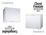
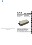
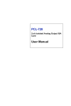
DSV Series
20, 25 & 27 inch
VideoWall Monitor’s
User’s Manual
DOTRONIX, INC.
160 First Street S.E.
New Brighton, Minnesota 55112-7894
612-633-1742
Fax: 612-633-7025
Publication No. 01054 Rev B
Dotronix Limited Warranty
Dotronix warrants that for one (1) year from date original purchase, it will, at its option, repair,
replace or refund the purchase price of any product which it manufactured that proves
defective in material or workmanship in normal use and service.
To obtain service under this Warranty, contact Dotronix Inc. at the address below, within one
(1) year of original purchase, to receive a Return Material Authorization (RMA) number.
Then ship the product believed to be defective, transportation prepaid, for inspection.
Dotronix shall not be responsible for unauthorized returns that do not list the RMA number
and quantity returned on the outside of the shipping container (i.e. on packing list in plain
view).
For products supplied without a frame (Less CRT and Printed Circuit Board Mounting), the
buyer must inspect the products within ten (10) days of receipt. After ten (10) days have
lapsed, there shall be no warranty coverage for broken or damaged parts, or misalignment
(i.e. broken torque seals where used). The products will be packed to allow Buyer to test
the unit within its packing carrier.
This Warranty applies only to goods manufactured by Dotronix Inc. Various component
parts manufactured by others (such as cathode ray tubes, semi-conductors, and fuses) are
covered by the separate warranty of their manufacturers. Where Dotronix, Inc. warranty
differs, only the warranty of the original component part manufacturer is offered. Of course,
the Dotronix warranty does not apply to CRT’s that are scratched, broken, burned or have
imperfections in any special coatings. It also does not apply to products which have been
altered, damaged, abused, or subjected to misuse, or repaired by anyone other than an
authorized Dotronix repair person.
All rights reserved. No part of this publication may be reproduced, stored in a retrieval system, or transmitted, in any form or
by any means, mechanical, photocopying, recording or otherwise, without the prior written permission of Dotronix, Inc. No
patent liability is assumed with respect to the use of the information contained herein. Where every precaution has been taken
in the preparation of this manual, Dotronix, Inc. and the author
assume no responsibility for errors or omissions. Neither is any
liability assumed for damage resulting from the use of the
information contained herein.
Specifications are subject to change due to technological
progress.
These displays require DHHS traceability under sub-part E, Section 1002.40 of the
Regulations for the Administration and Enforcement of the Radiation Control for Health and
Safety Act of 1968. It is the customer’s responsibility to maintain records that satisfy this
requirement.
THE TERMS OF THIS WARRANTY CONSTITUTES THE BUYER’S SOLE AND EXCLUSIVE REMEDY AGAINST DOTRONIX. THERE IS NO IMPLIED WARRANTY OF MERCHANTABILITY OR FITNESS FOR A PARTICULAR PURPOSE. UNDER NO CIRCUMSTANCE SHALL DOTRONIX BE LIABLE FOR INCIDENTAL AND CONSEQUENTIAL
DAMAGES, OR IN ANY AMOUNT BEYOND THE REPLACEMENT COST OF THE
ALLEGEDLY DEFECTIVE PART, REGARDLESS OF THE THEORY OF RECOVERY.
All products returned to Dotronix must include:
1. A tag or label on each unit with a description of the defect or reason
for return, or identify each unit on the packing list by serial number
and defect.
2. A packing list attached to the outside of the shipping container
showing the Return Material Authorization (RMA) Number and the
quantity returned.
Products returned that are not identified in accordance with the above procedure
will be refused and returned at Buyer's expense. To obtain a Return Material
Authorization (RMA) number contact the Service Department at:
DOTRONIX INC.
© Copyright 1995, Dotronix, Inc.
Publication No.01054 REV B
160 First Street S.E.
New Brighton, MN 55112-7894, USA
160 First Street S.E.
New Brighton, MN 55112-7894
Phone 612-633-1742 FAX 612-633-7025
REGULATORY NOTICES
DHHS: This product complies with applicable DHHS Standards under the
Radiation Control for Health and Safety Act of 1968.
X-Ray Precaution: This product includes critical electrical parts essential
for X-radiation protection. Under no circumstances should the operator
attempt to disassemble or modify the display.
WARNING: Changes or modifications not expressly approved by the party
responsible for compliance with the FCC’s rules (The FCC “Grantee”) could
void the user’s authority to operate this equipment.
NOTE: This equipment has been tested and found to comply with the
limits for a Class A digital device, following Part 15 of the FCC Rules.
These limits are designed to provide reasonable protection against
harmful interference when the equipment is operated in a commercial
environment. This equipment generates, uses, and can radiate radio
frequency energy and if not installed and used in accordance with this
operation manual, may cause interference to radio communications.
Operation of this equipment in a residential area is likely to cause
harmful interference, in which case the user will be required to correct
the interference at his or her own expense.
If necessary, the user should consult an experienced radio/television
technician for additional suggestions. The user may find the following
booklet prepared by the Federal Communications Commission helpful:
“How to Identify and Resolve Radio-TV Interference Problems”
This booklet is available from the U.S. Government Printing Office, Washington, DC 20402, Stock No. 004-000-00345-4.
It is necessary to use shielded interconnect cable with this monitor to insure
compliance with FCC Class A limits for radio frequency emissions.
PRECAUTIONS
This monitor contains circuits and components designed to meet specific
performance and safety requirements. No component changes may be
made without the written permission of the manufacturer.
To prevent electrical shock, do not attempt to disassemble the monitor.
There are no user-serviceable parts inside. Servicing, if required, should be
performed only by qualified service technicians familiar with the equipment
and safety procedures. Servicing by unauthorized personnel may be
dangerous and will void the warranty.
Do not use this monitor beyond its temperature and humidity range. This unit
is designed for indoor use. Ambient temperature range must not be above
113˚F or below 32˚F. Avoid using this monitor when the humidity is either
above 95% or less than 5%. Do not block the ventilation slots on the rear
side of the monitor. Allow for normal ventilation.
This monitor is equipped with a three prong grounding-type power plug. This
plug will only fit a grounding-type power outlet. Do not remove the grounding
pin on the power plug. This is a safety feature. If you are unable to insert
the plug into the outlet, contact an electrician to replace your power outlet.
Do not defeat the purpose of the grounding plug.
Position the monitor to avoid direct sunlight on the picture tube. Generally,
adjust the monitor for proper lighting and monitor position to minimize
undesirable reflections.
INTRODUCTION
Congratulations on your purchase of a new DSV Series VideoWall Monitor.
The DSV Series is available in either a 20 inch, 25 or 27 inch version in an
industrial metal cabinet.
This manual has been prepared to act as a guide in the operation of your
monitor. Please read the following operating instructions carefully before
using your monitor so that you are familiar with all of its features and
capabilities. All precautions and safety warnings should be read and strictly
observed.
UNPACKING THE MONITOR
To unpack your monitor:
1. Untape and open the top flaps of the packing carton. The monitor will
be cushioned by foam inserts. The back of the monitor will be facing up.
2. With the top open, carefully roll the monitor carton so the top of the box
is positioned down. Remove the monitor by lifting the box up and off the
monitor and the inserts. Caution: A firm hold on the monitor must be
constantly maintained while it is being removed from its packing carton.
3. A detachable power cord is provided with the monitor. Locate and
remove the power cord from the carton.
4. Inspect the monitor thoroughly for any damage that might have occurred
during shipping.
5. If any damage to the monitor is found, report it immediately to your
shipping carrier.
DO NOT RETURN DAMAGED MERCHANDISE TO THE MANUFACTURER UNTIL
AN APPROPRIATE CLAIM HAS BEEN FILED WITH THE CARRIER AND A
RETURN MATERIAL AUTHORIZATION NUMBER (RMA) HAS BEEN RECEIVED
FROM THE MANUFACTURER.
GETTING STARTED
1. Your monitor comes equipped with a detachable power cord with a three
prong type plug (AC ground). Attach the power cord to the connection
provided for it on the monitor. Plug the power cord into a wall receptacle
or power strip that will accept this type of plug.
2. Attach an input/output video cable or RGB cable (not included) from the
BNC video connection and /or RGB input in the rear panel of the monitor
to a compatible connector on your video equipment.
3. The ON/OFF switch is located on the rear side of the monitor (see
illustration). To turn on the monitor, push the ON/OFF switch to I.
Should further adjustment or alignment be necessary refer to the technical
service manual. For service, contact DOTRONIX, INC. customer service.
240 VAC OPTION
The DSV Series is available as an option configured for 240 VAC operation.
If you purchased a 240 VAC DSV Monitor these specifications apply:
■ Power requirements: 240VAC ± 10%, 50/60Hz
■ Power consumption: 150W nominal 27" & 25 " models
108 W nominal 20" model
■ Operating Temperature: 0˚ C to +45˚ C
(+32˚ F to 113˚ F)
■ Storage Temperature: -40˚ C to +70˚ C
(-40˚ F to 158˚ F)
■ Cooling: Convection cooling will be adequate for most installations. Each monitor requires a minimum of 500 BTU’s of cooling
or an air movement of 10 CFM per monitor. Internal cabinet
temperature must not exceed 55˚C (131 ˚F).
■ Stackability: Each monitor is enclosed in a heavy duty industrial
metal cabinet. Maximum recommended stack size is six units by
six units without additional support.
CRT COATINGS
As an option a factory installed anti-glare coating may have been applied to
the CRT surface of your monitor. Due to static electricity, the monitor screen
will attract dust and under normal use will acquire fingerprints. Recognizing
that most people will touch the screen sooner or later causing these
fingerprints. We recommend you implement a simple cleaning program.
The anti-glare coating on your monitor is very durable and will stand up to
routine cleaning. To prevent damage when cleaning, use a non-abrasive
household glass cleaner to remove smudges and fingerprints. Do not use
cleaners, papers, or cloths which contain abbrasives that may damage the
coating. Highly abrasive materials, scouring pads or acid solutions should
not be used. Care must be taken when handling and cleaning this surface.
This monitor was inspected prior to shipment and found to meet Dotronix
CRT coatings standard. The Dotronix warranty does not apply to CRT’s that
are scratched, or have imperfections in any special coatings.
HARC TEMPLATE
FRONT CONTROLS
Address Code Template:
Use this template to make a written note as to which monitor address is
assigned to each monitor location. Keep this for reference when making
adjustments. (Example A 1, A 2, A16, etc.)
Note: DSV20 has no controls in the front bezel
DSV27 controls are in the front lower right bottom of bezel.
* WHEN CONFIGURED FOR
DUAL RGB INPUT AND OPERATING
IN RGB2 MODE, FRONT CONTRAST
IS INOPERATIVE. CONTRAST FOR
RGB2 IS CONTROLLED ON THE
REAR PANEL
BRIGHTNESS CONTRAST* RED BKGD BLUE BKGD
TINT
IF NTSC EQUIPPED
DSV25 controls are in the four corners of the bezel
RED
BACKGROUND
BRIGHTNESS
HEIGHT
COLOR
LEVEL
TINT
BLUE
BACKGROUND
CONTRAST
IR WINDOW
BRIGHTNESS
Adjusts the brightness level for the desired overall
picture or display brightness.
NOTE: When operating in the NTSC video mode the Color Level and Tint
are located on the lower right side of bezel. A Height Control is also available
on the front bezel should some adjustment be necessary.
CONTRAST
Adjusts the contrast for the desired overall contrast.
TINT
If NTSC equipped, this control adjusts for the proper
color phase of flesh tones. (Inoperative in RGB mode
- Tint not available on PAL versions)
Monitor addresses can be reset in the field by qualified service technicians.
For more detailed information contact the factory.
RED BKGD
Adjusts the Red Background to achieve proper low
level gray scale.
BLUE BKGD
Adjusts the Blue Background to achieve proper low
level gray scale.
REAR CONTROLS
DSV27, 25
HARC OPERATING INSTRUCTIONS
DSV27 REAR PANEL
WITH OPTIONS IF SO EQUIPPED
Each monitor is shipped with a factory set address code, and will be factory
set in one of three Ranges; A, B or C plus a one or two digit number. You
can determine the address by checking the Address Code Label located
below the Serial Number on the monitor’s rear panel. To address a monitor;
LOOPING
BNC’S
RGB
DB-9 JACK
1. Set the Address Channel Range Selector to the letter designation
indicated on the Address Code Label.
➄➃➂➁➀
➈➇➆➅
TERMINATION
SWITCH
75Ω
HI-Z
DOUBLES AS
PRIORITY
SWITCH
OPTION
POWER AC WIDTH
VIDEO
CHROMA
(SCREWDRIVER ADJUSTABLE THRU BACK PANEL)
ON OFF
SELECT
NTSC
RGB
(PAL)
A
3. Rotate the Function Selector to number “1” designation.
DSV25 REAR PANEL
WITH OPTIONS IF SO EQUIPPED
LOOPING
BNC’S
2. Then rotate and set the Address Channel Selector to correspond with
the last one or two digits indicated on the Address Code Label.
4. Then press the Toggle Control (ID) up. The addressed monitor will
then Flash. The Flashing confirms the fact that you have addressed this
particular monitor. Make a note of this address and its position on the
template on the next page for future reference.
RGB
DB-9 JACK
➄➃➂➁➀
➈➇➆➅
TERMINATION
SWITCH
75Ω
HI-Z
DOUBLES AS
PRIORITY
SWITCH
OPTION
LOOPING BNC’S
POWER AC WIDTH
VIDEO
ON OFF
SELECT
NTSC
RGB
(PAL)
A
CHROMA
5. You may then proceed to make the necessary adjustments to the
Monitor via the Selector Functions listed below.
TINT (NOT ON PAL VERSION)
(SCREWDRIVER ADJUSTABLE THRU BACK PANEL)
1
2
BNC video for standard NTSC or PAL (if so equipped)
composite video inputs. Includes looping capability.
Slide the terminate switch to 75Ω when not looping the
video.
3
RGB
Sub D 9 Pin Jack analog video for the red, green, blue
and composite negative sync (RGBS) inputs. RGBS
inputs are self-terminating.
5
VIDEO SELECT
& PRIORITY
Selects between NTSC (or PAL) and RGB.
POWER
Push I to power unit ON. Push 0 to power unit OFF.
WIDTH
Adjusts the raster size horizontally to set the amount of
overscan needed.
CHROMA
Adjusts the color to the proper color saturation level.
(Inoperative in RGB mode)
TINT (25)
If NTSC equipped, this control adjusts for the proper
color phase of flesh tones. (Inoperative in RGB mode
- Tint not available on PAL versions)
4
6
7
8
Monitor ID – (See operating instructions above)
Brightness – Adjusts the brightness level for the desired overall
picture or display brightness.
Contrast– Adjusts the contrast level for the desired overall contrast.
Vertical Center– Allows for vertical position adjustment of video
within the raster.
Horizontal Center– Allows for horizontal position adjustment of
video within the raster (Up=Right • Down= Left).
Red Background– Adjusts the Red Background to achieve achieve
proper low level gray scale.
Green Background– Adjusts the Green Background to achieve
proper low level gray scale.
Blue Background– Adjusts the Blue Background to achieve achieve
proper low level gray scale.
HARC OPTION
REAR CONTROLS
DSV25, 27
This new DSV Series VideoWall Monitor is equiped with HARC Technology
– Handheld Addressable Remote Control, allowing the operator to remotely
align individual monitors independently of others when installed as a group
of monitors.
DSV25, 27 REAR PANEL
RGB ONLY
The following has been prepared to act as a guide in the operation of your
HARC equipped monitors. Please read the following operating instructions
carefully so that you are familiar with all of its features and capabilities before
using your HARC remote. All precautions and safety warnings should be
read and strictly observed.
➄➃➂➁➀
➈➇➆➅
Each HARC monitor can be identified by locating the IR Sensor window on
the lower right front of the bezel. This indicates that the monitor is equipped
with a factory installed receiver board allowing the monitor to be individually
addressed and controlled remotely.
DB-9 JACK
POWER AC WIDTH
ON OFF
DSV25, 27 REAR PANEL
DUAL RGB INPUTS
TOGGLE
CONTROL
UP
Increase
or
FUNCTIONS
1
2
3
4
MONITOR ID
BRIGHTNESS
CONTRAST
VERTICAL CENTER
5
6
7
8
HORIZONTAL CENTER
RED BACKGROUND
GREEN BACKGROUND
BLUE BACKGROUND
FUNCTION
7
8
6
DOWN
Decrease
– and for –
ID
UP
4
2
3
7
A
B
C
FUNCTION
Selector
8 9 10
6
5
4
3
2
1 16
11
12
13
14
15
RGB 1
RGB 2
➄➃➂➁➀
➈➇➆➅
➄➃➂➁➀
➈➇➆➅
POWER AC WIDTH
BLUE RED
ON OFF
TRIM TRIM
RGB2 RGB2 CONTRAST
RGB 2
1
5
ID
DOWN
ADDRESS
CHANNEL
RANGE
Selector
DB-9 JACKs
DOTRONIX
ADDRESS
CHANNEL
Selector
RGB PRIORITY
RGB 1 is the Master and RGB 2 is the Slave.
POWER
Push I to power unit ON. Push 0 to power unit OFF.
WIDTH
Adjusts the raster size horizontally to set the amount
of overscan needed.
BLUE TRIM
Adjusts RGB2 Blue Drive to achieve proper white
balance in relation to RGB1.
One Remote needed
per monitor group.
RED TRIM
Adjusts RGB2 Red Drive to achieve proper white
balance in relation to RGB1.
Operates on 9 Volt
Battery (included)
CONTRAST
Adjusts the contrast for the desired overall contrast
on RGB2 input.
CHANNEL SELECT
REAR CONTROLS DSV20
BRIGHTNESS
INTERNAL ADJUSTMENTS
Adjusts the brightness level for the desired overall
picture or display brightness.
CONTRAST
Adjusts the contrast for the desired overall contrast.
CHROMA
Adjusts the color to the proper color saturation level.
(Inoperative in RGB mode)
TINT
If NTSC equipped, this control adjusts for the proper
color phase of flesh tones. (Inoperative in RGB mode
- Tint not available on PAL versions)
DSV20 REAR PANEL
WITH OPTIONS IF SO EQUIPPED
WARNING
POTENTIAL SHOCK HAZARD IS PRESENT WHEN ADJUSTING THE
FOLLOWING CONTROLS, WHICH REQUIRE THE REMOVAL OF THE
REAR COVER.
VERTICAL SIZE:
Adjusts the vertical size of the display to fill the CRT
Screen.
VERT. CENTER:
If the active display area is not centered vertically on
the CRT screen after the vertical size has been adjusted, this control should be adjusted until the display
is centered.
HORIZ. FREQ:
If the display is tearing horizontally, the horizontal
frequency control may need adjustment. Signal quality should be checked before making any adjustments.
HORIZ. PHASE:
This control is adjusted to center active display area
horizontally on the CRT screen.
BRIGHTNESS
CONTRAST
➄➃➂➁➀
➈➇➆➅
TINT
(Screwdriver Adjustable)
POWER
ON OFF
DB-9 JACK
CHROMA
NOT USED ON THIS MODEL
LOOPING
BNC’S
PEAKING
V. HOLD
TERMINATION
SWITCH
75Ω
HI-Z
DOUBLES AS
PRIORITY
SWITCH
OPTION
VIDEO
WIDTH
SELECT RED
BLUE
NTSC
BALANCEA
(PAL)
PEAKING
VERTICAL
HOLD
AC
RGB
A
LOOPING BNC’S
BNC video for standard NTSC or PAL (if so equipped)
composite video inputs. Includes looping capability.
Slide the terminate switch to 75Ω when not looping the
video.
RGB
Sub D 9 Pin Jack analog video for the red, green, blue
and composite negative sync (RGBS) inputs. RGBS
inputs are self-terminating.
VIDEO SELECT
& PRIORITY
Selects between NTSC (or PAL) and RGB.
RED/BLUE
BALANCE
These two controls are used to balance the white
portion of RGB video to the caparable white portion of
the NTSC (or PAL) video.
WIDTH
Adjusts the raster size horizontally to set the amount of
overscan needed.
PEAKING
Adjust for desired picture. Turn clockwise to get a
crisper picture, or turn counterclockwise to get a softer
picture. (Inoperative in RGB mode)
VERTICAL HOLD
If the picture rolls adjust to stabilize the picture.
POWER
Push I to power unit ON. Push 0 to power unit OFF.
CONTRAST LIMIT: This control should be adjusted with the front panel
contrast control at maximum. It is to be set at 30 fL on
a white screen. Any attempt to set at a higher level may
permit CRT damage.
SUB BRIGHT:
This is a CRT set-up control. Do not adjust if the front
panel brightness control will bring up the background
raster when turned to maximum. If the raster cannot
be seen with the front panel control at maximum,
advance this control until the background raster is
barely visable.
The HORIZONTAL FREQUENCY and B+ ADJUST are factory preset.
Adjustment of these controls without proper test equipment may cause monitor operation outside specifications. Please refer to adjustment diagram on opposite
page for control locations.
V HOLD:
Monitors equipped with the NTSC (or PAL) option will
have an automatic Vertical Hold circuit that requires no
adjustment. Monitors with only the RGB input uses
VR1 as the Vertical Hold control.
SPECIFICATIONS
INTERNAL ADJUSTMENTS
■
■
■
■
■
■
Warning!
The adjustment of these controls should be made only by
qualified Service Personnel.
Horizontal Scan Rate: 15.75 kHz ± 500 Hz
Vertical Sweep Rate: 60 Hz ± 5%
Video Bandwidth: 10 MHz (-3db)
CRT Sizes: 20-inch, • 25-inch, • 27-inch
Resolution: 500 + lines
RGB Analog input DB 9 Pin Jack with composite negative sync.
➄➃➂➁➀
➈➇➆➅
CONTRAST
LIMIT
DB 9 PIN JACK
VR4
VR10
NOTE: CONTROL LOCATIONS
SHOWN ARE FOR THE DSV27
AND 25 MODELS. ON THE DSV20
THE LOCATIONS ARE SIMILAR.
SUB
BRIGHTNESS
■
H. LIN.
U2
L7
VR1
VR14
■
RGB VIDEO
INPUT
9 PIN D-SUB
1
0N/0FF
POWER
SWITCH
■
VR16
B+
ADJUST
AC
FILTER
0
Power requirements: 120 VAC ± 10%, 60 Hz
Power consumption: 150 W nominal 27" & 25" models
108 W nominal 20" model
Operating Temperature: 0˚C to +45˚C
(+32˚F to +113˚F)
Storage Temperature: -40˚C to +70˚C
( -40˚F to +158˚F)
Cooling: Convection cooling will be adequate for most installations.
Each monitor requires a minimum of 500 BTU’s of cooling or an air
movement of 10 CFM per monitor. Internal cabinet temperature
must not exceed 55˚C (131˚F).
Stackability: Maximum recommended size is six units by six units
without additional support.
Agency Approvals: UL, CSA, FCC Class A
(BOTTOM)
Screen
G2
CAUTION
HIGH VOLTAGE
FUSE
2.5 AMP
SLO BLO
■
■
(TOP)
FOCUS
WARNING-AC POWER
■
■
AC LINE
CORD
Brightness
Contrast
Tint (on 27" NTSC version)
Red Background
Blue Background
Rear Controls:
H.
PHASE
VR15
VR12
VR11
(MODEL DEPENDENT)
Function
Red Input (.7 Vp-p)
Green Input (.7 Vp-p)
Blue Input (.7 Vp-p)
GND
GND
Comp. Neg. Sync. (0.5 to 4.0 Vp-p)
N/C
N/C
N/C
■
H. FREQ
V.
SIZE
-OR-
COMB FILTER
V. CENTERING
VERT
HOLD
Front Controls 27, 25:
(Accessed from the rear on the DSV20)
Pin
1
2
3
4
5
6
7
8
9
WIDTH COIL
■
Horizontal Width, Chroma (on NTSC & PAL
versions), Tint (on 25" - NTSC versions only),
Switchable 75Ω termination (NTSC or PAL
versions), Video Select & Priority if option is
installed.
Power ON - OFF
MECHANICAL DIMENSIONS
WALL INSTALLATIONS
Cooling:
WIDTH
A
.125
HEIGHT
B
C
.125
Convection cooling will be adequate for most installations. Each monitor requires a minimum of 500 BTU’s of
cooling or an air movement of 10 CFM per monitor.
Internal cabinet temperature must not exceed 55˚C (131 ˚F).
Stackability: Each monitor is enclosed in a heavy duty industrial metal
cabinet. Maximum recommended stack size is six
units by six units without additional support.
D
DEPTH
E
MECHANICAL DIMENSIONS unit = inch (mm)
Height
Width
Depth
A
B
C
D
E
DSV20
15.0"(381)
18.31" (465)
17.125" (435)
14.94" (379)
19.0" (483)
12.75"(324)
1.62"(41)
1.62"(41)
DSV25
17.69"(449)
23.00"(584)
17.86"(454)
18.75"(476)
24.65"(626)
12.75"(324)
2.28"(58)
2.14"(54)
Weight
66 lbs (30 kg) 87 lbs (39.5 kg)
Shipping 72 lbs (32.7 kg) 93 lbs (42 kg)
DSV27
19.12"(486)
24.12"(613)
18.4"(467)
22.0"(559)
27.0"(686)
12"(305)
3.44"(87)
1.56"(40)
105 lbs (47.6 kg)
115 lbs (52 kg)
MOUNTING PLATE/
TIE BRACKET
Order Part Number
13027526-007