1
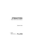
M32 SERIES DISPLAY
32 inch
160 FIRST STREET S.E.
ST. PAUL, MN 55112-7894
PHONE 651-633-1742
FAX: 651-633-1065
www.dotronix.com
Publication No. 01099 Rev A
User’s Manual
PRECAUTIONS
This monitor contains circuits and components designed to meet specific
performance and safety requirements. No component changes may be
made without the written permission of the manufacturer.
To prevent electrical shock, do not attempt to disassemble the monitor.
There are no user-serviceable parts inside. Servicing, if required, should be
performed only by qualified service technicians familiar with the equipment
and safety procedures.
Servicing by unauthorized personnel may be dangerous and will void
the warranty.
If any damage to the monitor is found, report it immediately to Dotronix.
DO NOT RETURN DAMAGED MERCHANDISE TO THE MANUFACTURER UNTIL
AN APPROPRIATE CLAIM HAS BEEN FILED WITH THE CARRIER AND A
RETURN MATERIAL AUTHORIZATION NUMBER (RMA) HAS BEEN RECEIVED
FROM THE MANUFACTURER.
All rights reserved. No part of this publication may be reproduced, stored in a retrieval system, or transmitted, in any form
or by any means, mechanical, photocopying, recording or
otherwise, without the prior written permission of Dotronix, Inc.
No patent liability is assumed with respect to the use of the
information contained herein. Where every precaution has
been taken in the preparation of this manual, Dotronix, Inc. and
the author assume no responsibility for errors or omissions.
Neither is any liability assumed for damage resulting from the
use of the information contained herein.
Specifications are subject to change due to technological
progress.
© Copyright 1999, Dotronix, Inc.
Publication No.01099A
160 First Street S.E.
St. Paul, MN 55112-7894, USA
Dotronix Limited Warranty
Dotronix warrants that for one (1) year from date original purchase, it
will, at its option, repair, replace or refund the purchase price of any product which it
manufactured that proves defective in material or workmanship in normal use and service.
To obtain service under this Warranty, contact Dotronix Inc. at the address below, within
one (1) year of original purchase, to receive a Return Material Authorization (RMA) number.
Then ship the product believed to be defective, transportation prepaid, for inspection.
Dotronix shall not be responsible for unauthorized returns that do not list the RMA number
and quantity returned on the outside of the shipping container (i.e. on packing list in plain
view).
For products supplied without a frame (Less CRT and Printed Circuit Board Mounting), the
buyer must inspect the products within ten (10) days of receipt. After ten (10) days have
lapsed, there shall be no warranty coverage for broken or damaged parts, or misalignment
(i.e. broken torque seals where used). The products will be packed to allow Buyer to test
the unit within its packing carrier.
This Warranty applies only to goods manufactured by Dotronix Inc. Various component
parts manufactured by others (such as cathode ray tubes, semi-conductors, and fuses ) are
covered by the separate warranty of their manufacturers. Where Dotronix, Inc. warranty
differs, only the warranty of the original component part manufacturer is offered. Of course,
the Dotronix warranty does not apply to CRT's that are scratched, broken, burned or have
imperfections in any special coatings. It also does not apply to products which have been
altered, damaged, abused, or subjected to misuse, or repaired by anyone other than an
authorized Dotronix repair person.
These displays require DHHS traceability under sub-part E, Section 1002.40 of the
Regulations for the Administration and Enforcement of the Radiation Control for Health and
Safety Act of 1968. It is the customer's responsibility to maintain records that satisfy this
requirement.
THE TERMS OF THIS WARRANTY CONSTITUTES THE BUYER'S SOLE AND EXCLUSIVE REMEDY AGAINST DOTRONIX. THERE IS NO IMPLIED WARRANTY OF MERCHANTABILITY OR FITNESS FOR A PARTICULAR PURPOSE. UNDER NO CIRCUMSTANCE SHALL DOTRONIX BE LIABLE FOR INCIDENTAL AND CONSEQUENTIAL
DAMAGES, OR IN ANY AMOUNT BEYOND THE REPLACEMENT COST OF THE
ALLEGEDLY DEFECTIVE PART, REGARDLESS OF THE THEORY OF RECOVERY.
All products returned to Dotronix must include:
1. A tag or label on each unit with a description of the defect or reason for return,
or identify each unit on the packing list by serial number and defect.
2. A packing list attached to the outside of the shipping container showing the
Return Authorization Number (RMA) and the quantity returned.
Products returned that are not identified in accordance with the above procedure will be
refused and returned at Buyer's expense.
To obtain a Return Material Authorization (RMA) number contact:
DOTRONIX INC.
160 First Street S.E. • St. Paul • Minnesota • 55112-7894
Phone 651-633-1742 • FAX 651-633-1065
27
4.4
Trouble Shooting
Table of Contents
If your monitor fails to operate correctly, consult the following chart for
possible solutions before calling for repairs.
Condition
1. The picture does not
appear
2. The screen is not
synchronized:
Check Point
Check to make sure the signal cable is
firmly seated in the socket.
Check to see if the computer system
power is on.
Check the brightness control is at appropriate position, not at the minimum.
Check to make sure the signal cable is
firmly seated in the socket.
Check the output level matches the input
level of your computer.
Make sure the signal timings of the computer systems is within the specification
of the monitor.
3. The position of the
screen is not in the
center:
Adjust the H-size, H-Position, or V-Size,
V-Position control.
4. The screen is too bright
(too dark)
Check if the brightness of contrast control
is at the appropriate position, not at the
maximum (minimum).
Check if the signal timing of the computer
is within the specification of the monitor.
Especially check the horizontal frequency.
5. The screen is shaking.
Move all objects which emit a magnetic
field such as a motor or transformer, away
from the monitor.
Check if the specified voltage is applied.
Check if the signal timing of the computer
system is within the specification of the
monitor.
CHAPTER 1 INSTRUCTION
2
1.1
1.2
1.3
1.4
2
2
3
4
General Information
FCC Statement
IMPORTANT SAFETY INSTRUCTIONS
Technical service warning for x-ray radiation protection
CHAPTER 2 INSTALLATION
6
2.1
2.2
6
7
The Product
Connecting
CHAPTER 3 USING YOUR MONITOR
88
3.1
3.2
8
8
Control locations
Function adjustments
CHAPTER 4 DISPLAY DATA
10
4.1
4.2
4.3
4.4
10
11
11
12
Appendix A: Specifications
Appendix B: Pin Assignments
Appendix C: Display Compatibility
Troubleshooting
If you are unable to correct the fault by using this chart, discontinue using
your monitor and contact your distributor or dealer for further assistance.
12
1
CHAPTER 1 INSTRUCTION
1.1
4.2
Appendix B: Pin Assignments:
General Information
Welcome to the exciting world of high-resolution graphics with your purchase of this large screen color display monitor. It was designed to meet
the requirement of screen performance for demanding business and industry application now adays. It delivers a large screen area, higher resolution, and greater color accuracy.
This monitor is designed to operate under a multitude of hardware platforms and video standards (see appendix C) , its multi-sync function automatically adjusts the monitor scanning frequency to the user’s video card.
Pin
Description
Pin
Description
1
2
3
4
5
6
7
8
Red
Green
Blue
Ground
Ground
Red Rtn
Green Rtn
Blue Rtn
9
10
11
12
13
14
15
No-Connection
Ground
Ground
bidirectional Data (SDA)
H. Sync
V. Sync
Data Clock (SCL)
This powerful and intelligent large screen color monitor can provide more
active display area, auto sizing, auto-centering and perfect geometry.
The non-interlaced mode offers flicker-free screen images, which reduces
eyestrain and fatigue, so you can feel more comfortable in front of the screen
for even longer periods.
The microprocessor control system enhances your ability to control display
on screen, so you can adjust desired screen more easily.
1.2
FCC Statement:
Note: This equipment has been tested and found to comply with the limits
for a class A digital device, pursuant to part 15 of the FCC rules, these limits
are designed to provide reasonable protection against harmful interference
in a residential installation, this equipment generates, uses and can radiate
radio frequency energy and, if not installed and used in accordance with
the instructions, may cause harmful interference to radio communications,
however, there is no guarantee that interference will not occur in a particular installation, if this equipment does cause harmful interference to radio or
television reception, which can be determined by turning the equipment off
and on, the user is encouraged to try to correct the interference by one or
more or the following measures
—Reorient or relocate the receiving antenna.
—Increase the separation between the equipment and receiver.
—Connect the equipment into an outlet on a circuit different from
that to which the receiver is connected.
—Consult the dealer or an experienced radio/TV technician for help.
2
D – Sub Type 15P
Note: Pin 12 & Pin 15 are for DDC use only
4.3
Appendix C: Display Compatibility:
Format
Hor. Freq.
Vert. Freq.
640 x 350
640 x 400
640 x 480
640 x 480
800 x 600
640 x 480
800 x 600
800 x 600
1024 x 768
1024 x 576
920 x 518
31.5 kHz
31.5 kHz
31.5 kHz
35.0 kHz
35.2 kHz
37.8 kHz
37.8 kHz
48.1 kHz
48.4 kHz
48.0 kHz
47.0 kHz
70 Hz
70 Hz
60 Hz
67 Hz
56 Hz
72 Hz
60 Hz
72 Hz
60 Hz
70 Hz
75 Hz
11
CHAPTER 4 DISPLAY DATA
4.1
Appendix A: Specifications
Specification:
Picture Tube:
Input Signal:
Resolution:
Synchronization:
Video Bandwidth:
Display size:
Power Supply:
Dot Pitch (mm):
Power Consumption:
Dimension:
Weight
Regulations:
Operating Temperature:
Audio Amplifier:
10
32 inch, 108 degree deflection, super flat
square screen, dual-axis dynamic focus,
47% transmission,
Video: analog 0.7Vpp/75 ohm positive,
Sync: Separate Sync TTL Level,
positive/negative.
See Appendix C
Horizontal: 31 kHz –50 kHz (Automatically)
Vertical: 50 Hz – 120 Hz (Automatically)
68 MHz at +/- 3db
Horizontal: 26.10 inch, 663 mm (Adjustable)
Vertical: 14.70 inch, 373 mm (Adjustable)
115/230 VAC (Auto switching), 50/60 Hz
0.75, antiglare/antistatic coating
240W (max.)
Width: 30.00, Height: 18.69, Depth: 20.31
(Does not include CRT face protrusion)
Net weight: 130 lb.
UL/cUL, DHHS, FCC CLASS A
0ºC –40ºC (32ºF – 104ºF)
Humidity: non-condensing 20%-90% RH
Altitude: 0 -10,000 feet
No Speakers provided.
Notice
(1) The changes or modifications to the equipment not expressly approved
by the party responsible for compliance could void the user’s authority
to operate the equipment.
(2) Shielded interface cables and AC power cords, if any, must be used in
order to comply with the emission limits.
1.3
IMPORTANT SAFETY INSTRUCTIONS
1. Read all of these instructions.
2. Save these instructions for later use.
3. Unplug this product from the wall outlet before cleaning. Do not use
liquid cleaners or aerosol cleaners. Use a damp cloth for cleaning.
4. Do not use attachments not recommended by the monitor manufacturer as they may cause hazards.
5. Do not use this monitor near water. For example near a bathtub, washbowl, kitchen sink, or laundry tub, in a wet basement, or near a swimming pool, etc.
6. Do not place this monitor on an unstable cart, stand or table. The monitor may fall, causing serious injury to a child or adult and serious damage to the appliance. Use only with a cart or stand recommended by
the manufacturer or sold with monitor. Wall or shelf mounting should
follow the manufacturer’s instructions, and should use a mounting kit
approved by the manufacturer.
7. Slots and openings in the cabinet at the back or bottom are provided for
ventilation; and to ensure reliable operation of the product and protect it
from overheating, these openings must not be blocked or covered.
Placing the monitor on a bed, sofa, rug, or other similar surface should
never block the openings. This monitor should never be placed near or
over a radiator or heat register. This monitor should not be placed in
built-in installation such as a bookcase unless proper ventilation is provided.
8. This monitor should be operated only from the type of power source
indicated on the marking label. If you are not sure of the type of power
supplied in your home, consult your monitor dealer or local power company.
9. This monitor is equipped with a three-wire grounding type plug, a plug
having a third (grounding) pin. This plug will only fit into a groundingtype power outlet. This is a safety feature. If you are unable to insert
the plug into the outlet, contact your electrician to replace your obsolete
outlet. Do not defeat the safety purpose of the grounding-type plug.
10. Do not allow anything to rest on the power cord, do not locate this monitor where persons working on it will abuse the cord.
3
11. Follow all warnings and instructions marked on the monitor.
12. For added protection for this monitor, when it is unattended and unused
for long periods of time, unplug it from the wall outlet. This will prevent
damage to the monitor due to power-line surges.
13. Do not overload wall outlets and extension cords as this can result in
fire or electric shock.
14. Never push objects of any kind into this monitor through cabinet slots
as they may touch dangerous voltage points or short out parts that could
result in a fire or electric shock. Never spill liquid of any kind on the
monitor.
15. Do not attempt to service this monitor yourself since opening or
removing covers may expose you to dangerous voltage or other hazards. Refer all servicing to qualified service personnel.
16. Unplug this monitor from the wall outlet and refer servicing to qualified
service personnel under the following conditions:
a. When the power cord or plug is damaged or frayed.
b. If liquid has been spilled into the monitor.
c. If the monitor has been exposed to rain or water.
d. If the monitor does not operate normally by following the operating
instructions, adjust only those controls that are covered by the
operating instructions as improper adjustment of other controls may
result in damage and will often require extensive work by a qualified technician to restore the monitor to normal operation.
e. If the monitor has been dropped or the cabinet has been damaged.
f. Where the monitor exhibits a distinct change performance, this
indicates a need for service.
17. When replacement parts are required, be sure the service technician
has used replacement parts specified by the manufacturer that has the
same characteristics as the original parts. Unauthorized substitutions
may result in fire, electric shock, or other hazards.
18. Upon completion of any service or repairs to this monitor, ask the service technician to perform routine safety checks to determine that the
monitor is in safe operating condition.
19. The sound pressure level at the operators position according to IEC
704-1:1982 is equal or less that 70dB(A).
1.4
Technical service warning for x-ray radiation protection
This product contains electrical and mechanical parts essential for x-ray
protection.
For replacement purposes, use only part types shown in the parts list.
4
” and “
” button to adjust contrast.
3. Contrast:
To press “
4. Brightness:
To press “ ” and “ ” to adjust brightness.
5. Size:
Contains vertical and horizontal size functions.
a. Vertical size:
b. Horizontal size:
Increasing the vertical display size by pressing
the “size” and “ ” button at the same time.
Decreasing the vertical display size by pressing
the “size” and “ ” button at the same time.
Increasing the horizontal display size by pressing the “size” and “ ” button at the same time.
Decreasing the horizontal display size by pressing the “size” and “ ” button.
6. Vol/Tilt:
Contains volume and tilt functions.
a. Volume:
(Not Used)
Increasing the volume by pressing the “volume”
and “ ” button at the same time.
Decreasing the volume by pressing the “volume”
And “ ” button at the same time.
The screen turns clockwise or anti clockwise by
pressing the “tilt”, “ ” button or the “tilt”, “ ”
button.
b. Tilt:
7. Degaussing:
Eliminate color impurity by pressing the degaussing button.
8. Recall:
To recall last record by pressing “ ” and “ ”
button at the same time.
9. LED and power saving indicator (Not shown):
a.
b.
The green LED indicator lights when the main
power is on.
The LED will change from the green to the
orange indicator when the monitor switches from
“on mode” to “suspend mode”.
10. Power switch:
Turn main power on or off.
9
Chapter 3
3.1
USING YOUR MONITOR
Control locations
Degauss Volume V Size
V Position Parallelgram
Using the Right Power Cord.
For units used at 115 VAC: Use a UL – Listed cord set consisting of a
minimum No. 18 AWG, type SVT or SJT, rated 6A 125 VAC: threeconductor cord a maximum of 15 feet in length, and a parallel – blade,
grounding – type attachment plug.
For units used at 230V (domestic use): Use a UL-Listed cord set consisting of a minimum No. 18 AWG Type SVT or SJT, rated 6A, 250 VAC:
three-conductor cord a maximum of 15 feet in length, and a tandem –
blade, grounding – type attachment plug.
Tilt H Size
3.2
Brightness Contrast H Position Pincushion
Function adjustments
1. Geometry:
Contains pincushion and parallelogram functions
a. Pincushion:
(Geometry)
Increasing the middle of picture area to barrel
shape by pressing the “geometry” and “ ” button
at the same time.
Decreasing the middle of picture area to narrow
shape pressing the “geometry” and “ ” button at
the same time.
Moving the upper part of the screen to the right by
pressing the “geometry” and “ ” button at the
same time.
Moving the lower part of the screen to the right by
pressing the “geometry” and “ ” button at the
same time.
b. Parallelogram:
(Geometry)
2. Position:
Contains vertical and horizontal position function
a. Vert. position:
Moving the picture up by pressing the “position”
and “ ” button at the same time.
Moving the picture down by pressing the “position”
and “ ” button at the same time.
Moving the picture left by pressing the “position”
and “ ” button at the same time. Moving the picture right by pressing the “position” and “ ” button at the same time.
b. Horiz. position:
8
5
Chapter 2 INSTALLATION
2.1
2.2
Connecting
AC
POWER
The Product
Before using this monitor, please make sure that all the items listed below
are presented in your package.
1.
VGA IN
Large screen color monitor
VGA
OUTPUT
VGA IN
VGA OUT
R
L
AUDIO
AC INPUT
POWER
INPUT
REAR OF CABINET
AUDIO
NOT USED
The procedure of setting up your large screen monitor as follows:
1. Switch off the power to both your monitor and computer, the location of
the power switch is on the upper rear of the monitor.
2.
2.
User’s manual
M32 SERIES DISPLAY
32 inch
User’s Manual
3.
4.
Power cable connection:
Connect one end of the main power cord to main power socket at the
rear of the monitor, and connect the other end of the cord to the main
power supply.
Note: This monitor is set to operate using a 115/230 VAC +/- 10%, 60/
50Hz power supply, if the voltage in your home is different from this,
consult your dealer.
3.
Input Signal cable connection:
Connect one end of the signal cable to the 15 pin D-Sub adapter at the
rear of the monitor (VGA IN), and connect the other end of the signal
cable to the computer.
4.
Output Signal Connection:
Connect one end of the signal cable to the 15 pin D-Sub adapter at the
rear of the monitor (VGA OUT), and connect the other end of the signal
cable to one other monitor.
5.
Audio signal connection: (Not Used)
Connect one end of the signal wire to the rear of the monitor, and
connect the other end of the signal wire to the audio device.
Power cord
Signal cable
*
6
No Speakers provided.
7