1
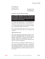
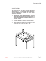
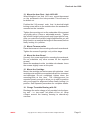
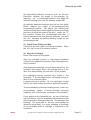
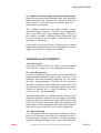
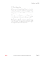
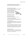
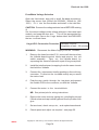
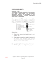
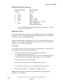
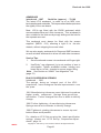
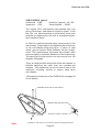
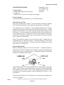
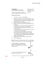
LINN LP12
TURNTABLE
SET UP MANUAL
Revised Jan 1998
IN THE BEGINNING ...
This is where it all began back in 1973 - the Sondek LP12,
which revolutionised people’s perception of what produces ‘good’ hi-fi. At Linn we have demonstrated that
turntables are the most important component in a record
playing hi-fi system. Twenty five years after its introduction, the LP12 is still the reference turntable.
Since 1973, Linn has invested a great deal of time and
effort upgrading the LP12; improvements which have
had far reaching effects on the whole system. Today,
the LP12 sounds significantly better than at any time in
its history, and has an ever expanding customer base.
Looking after ‘yesterday’s' customer has always been
a priority at Linn, ensuring that almost all the upgrades
are retrofittable, thus making it possible to upgrade any
LP12 to current specification and performance.
This section is designed to assist you to carry out any
requested upgrades to the LP12, to help you identify and
correct minor irregularities, to familiarise you with recommended tools and provide useful information on LP12
specifications. We hope this section will help you provide
better service to all your existing and future LP12
customers.
INDEX
Copyright © 1991-1998 by Linn Products Limited. All Rights Reserved.
Page 2
Revised Jan 1998
INDEX
Contents ................................................. Page
LP12 Introduction .............................................. 2
LP12 Set-up ...................................................... 4
Required Tools ......................................... 5
Set-up Jig ................................................. 6
Preparation ............................................... 7
Assembly .................................................. 10
Suspension Adjustments .......................... 14
Arm cable fitting ........................................ 17
Motor adjustment ...................................... 21
Final Installation ....................................... 23
Tips ........................................................... 24
Common Turntable Set-up Faults ..................... 25
LP12 Fault Finding ............................................ 26
Lingo Fault Finding ........................................... 32
LP12 Guidelines for Upgrade and Repair
Lingo ......................................................... 33
Suspension Grommets ............................. 36
Motor Thrust Bearing ................................ 37
Bearing Housing “CIRKUS” ...................... 38
Armboard .................................................. 41
Suspension Springs .................................. 41
Sub-chassis (glued) .................................. 42
Plinth ......................................................... 43
Valhalla Power Supply .............................. 44
Nirvana Kit ................................................ 45
Valhalla Repair Kit .................................... 46
Valhalla Update Kit ................................... 47
Motor Adjustments .................................... 48
Linn Speedchecker ................................... 50
Kinky Arm Alignment Tool ........................ 51
T-Bar Bolt Straightener ............................. 52
45-rpm Adaptor ......................................... 53
LP12 History and Upgrade Path ....................... 54
LP12 Specifications........................................... 57
Separate Documents:
LP12 Circuitry Fitting Instructions for Basik/Valhalla/Lingo including
Wiring Diagram for Early LP12 ......................... LP12_tech_circuitry.pdf
LP12 Trampolin Fitting Instructions .................. LP12_tech_baseboard.pdf
LP12 Motor Flush Instructions .......................... LP12_tech-motorflush.pdf
INDEX
Copyright © 1991-1998 by Linn Products Limited. All Rights Reserved.
Page 3
Revised Jan 1998
LP12 SET-UP
INTRODUCTION
Estimated Time
for Completion of
task ~ 60 minutes
Important - read this before you begin
It is extremely important that you read this entire
section before attempting to set up a Linn Sondek
LP12 Turntable. Failure to do so may well result in
substandard performance, and could result in permanent damage to the turntable.
We realise that the policy of most hi-fi dealers is, “If
all else fails, read the instructions”. The set up procedure
used on the Linn Sondek, while not terribly difficult, is
significantly different from that used on other turntables.
It is virtually impossible to set the table up correctly
without following the steps in this section.
These instructions refer specifically to the set up of the
Linn Sondek LP12 fitted with a Linn Tonearm and
cartridge.
Tightening Procedure
Since we are dealing with a transducer that has to recover
information considerably smaller than a millionth of an
inch from a phonograph record, it is important that all
fasteners (screws, nuts, and bolts) in the turntable be
very tight. Whenever the instructions call for you
to tighten a fastener, we do mean tight - probably tighter
than you would have imagined.
However, there is no advantage to tightening past the
point where materials will deform, or where you damage
the materials or destroy their structure. A good rule of
thumb is simply to bring the nut or screw up to where it
seems tight and then turn it about 1/8 turn more (in the
case of armboard screws, which are put into wood, 1/16
turn will do).
INDEX
Copyright © 1991-1998 by Linn Products Limited. All Rights Reserved.
Page 4
Revised Jan 1998
Tools Needed For Set-Up
5.5mm or 7/32 Hollow Shaft Nut Driver
8mm or 5/16 Hollow Shaft Nut Driver
No. 1 Pozidrive Screwdriver
No. 2 Pozidrive Screwdriver
All cross slot screws on the LP12 are Pozidrive. While a
Phillips screwdriver will work, the correct Pozidrive screwdriver is preferred.
Medium Size (about 5 mm wide) Flat Blade Screwdriver
Medium Size Needle Nose Pliers
12mm or Adjustable Wrench
5mm or 3/16 Wrench
1.33mm Allen Key
2mm Allen Key
3mm Allen Key
4mm Allen Key
Required allen keys, except for the 3mm, are supplied with
Linn tonearms.
Turntable Set-Up Jig or Substitute
It is desirable to raise the turntable to about eye level so
that you can reach and see the underside of the turntable.
The set-up jig on a standard-height work bench is best.
The surface that the set-up jig or turntable rests upon
must be absolutely steady and level for proper suspension adjustment. If the surface is unsteady or subject
to rocking motion, the energy put into the suspension
during the adjustment process can induce movement in
the support surface as well as the suspension. Proper
adjustment of the turntable suspension will be difficult,
if not impossible under these conditions.
INDEX
Copyright © 1991-1998 by Linn Products Limited. All Rights Reserved.
Page 5
Revised Jan 1998
LP12 SET-UP JIG
We recommend that you always use a set-up jig when
setting up an LP12. This will facilitate ease of adjustment,
prevent damage to your turntable and ensure proper
suspension adjustment.
1.
Before using the jig make sure that the mounting
plates have been covered with a protective strip. Fit
protection to underside of clamp and place the jig on
a stable surface.
2.
Fit plinth carefully to set-up jig and lock in place.
3.
Adjust jig feet until plinth is level. Check with a spirit
level, both front to back and side to side.
l
ve
ç
INDEX
le
è
ç
lev
el
è
Copyright © 1991-1998 by Linn Products Limited. All Rights Reserved.
Page 6
Revised Jan 1998
PREPARATION
The next steps cover unpacking the turntable and checking to see that none of the fasteners (screws, nuts or
bolts) have become loose due to vibration in transit.
Caution
Make sure that the turntable is unplugged from the A/C
outlet before removing the bottom cover. High Voltages
(400 Volts!!!) are present on the Valhalla circuit board.
Failure to observe this precaution can result in serious
electrical shock.
Please note that, on turntables equipped with the Valhalla
circuit board, the board is live at all times. The Valhalla
switch does not turn the
A/C power on and off; it simply sends a control pulse to
the board which results in the motor being turned on or off.
1. Unpack the Turntable
Packed below the dustcover you will find:
An armboard
Two dustcover hinges
Two baseboard screws
Three armboard screws
One inner platter/spindle assembly
Two phials of main bearing oil
Underneath the turntable you will find:
The outer platter, felt mat, and belt
2. Place Turntable in Set-up Jig
After placing the turntable in the set-up jig, lock the
turntable into place. Use a spirit level to ensure that the
turntable plinth (base) is level. This is done by adjusting
the feet of the set-up jig.
Please note that if you are using a Linn set-up jig, you may
lay the jig on its back at various times during set-up to
provide easier access to the underside of the turntable
(steps 3 to 6 for example).
However, when this is done you should first remove the
inner platter and cap the main bearing well with the red
plastic cover provided to avoid spillage from the bearing
housing if it has been charged with oil.
INDEX
Copyright © 1991-1998 by Linn Products Limited. All Rights Reserved.
Page 7
Revised Jan 1998
3. Remove Baseboard
Before proceeding with this step, stop and check to make
sure the turntable is unplugged! To remove the baseboard, unscrew and remove the four feet on the bottom
of the turntable.
If you are working on a previously set-up table, you will
also have to remove the two baseboard screws that are
located in the centre of both the front and rear edges of
the baseboard.
NOTE: If the turntable is to be repacked in its original
carton, the two baseboard screws must be removed. If
left in, they will scratch the rim of the platter which is
packed directly under the turntable.
4. Remove ground and P-Clip Nuts
Use the 8mm nut driver to remove the nut holding the
turntable earth jumper wire to the front chassis bolt, and
the nuts holding the nylon P-clip, washer, and green
A/C ground wire (if fitted) to the rear chassis bolt. (See
Turntable Exploded View).
5. Tighten Wiring Strap Nuts
Check to see that the nuts holding the wiring strap, on
which the circuit board is mounted, are tight. These nuts
are located directly
under the ones just removed. The chassis bolts pass
through the wood mounting blocks of the plinth. These
wooden blocks may expand and contract due to
temperature and humidity extremes during transit and
this can result in the nuts working loose.
Observe the top surface of the stainless steel top plate as
you tighten these nuts. Do not overtighten these nuts
such that the stainless steel top plate becomes depressed or deformed beneath the heads of the chassis
bolts.
6. Tighten Sub-chassis Ground Screw
Tighten the allen head screw which attaches the chassis
earth jumper wire to the right rear edge of the sub-chassis.
With older turntables that do not have this screw, proceed
to the next step or if welded type,drill the side of subchassis and relocate earth wire.
INDEX
Copyright © 1991-1998 by Linn Products Limited. All Rights Reserved.
Page 8
Revised Jan 1998
7. Tighten Top Plate Screws
By looking down at the stainless steel top plate from
above, locate the two small pozidrive screws that help to
attach the top plate to the plinth. They can be found next
to the chassis bolts located at the centre front and centre
rear of the top plate. Ensure that these two screws are
tight.
8. Check the Position of the Motor
Check the position of the motor mounting bolts in the
elongated slots in the top plate. These are the two bolts
on the extreme right and left of the motor.
On current turntables, (50 Hz pulley, 21mm diameter)
the motor mounting bolts should be in the middle of the
adjustment range. While this can be accomplished
by carefully aligning each of the two motor mounting
screws in the middle of the slot provided, it is easier
and far more accurate to simply have one motor mounting
bolt at the extreme outside of its slot, and the other motor
mounting bolt at the extreme inside of its slot.
In countries with 60 Hz mains supplies, older turntables
may have a smaller (17 mm) diamter pulley. On these
LP12s the motor should be in the outermost position. This
is accomplished by having both motor mount bolts at the
extreme outside of their slots.
Please note:
All new turntables are factory fitted with the larger,
50Hz pulley, and thus should have one motor
mounting bolt at the extreme outside of its slot and
the other motor mounting bolt at the extreme inside
of its slot.
Both Lingo and Valhalla power Suplies use the 50Hz
motor/pulley.
Motors with 60 Hz pulleys as supplied in the appropriate BASIK power supply kit and are not compatible with the Lingo or Valhalla power supply.
Original Valhallas supplied to countries with 60 Hz
mains were supplied 60 Hz Valhalla boards.
INDEX
Copyright © 1991-1998 by Linn Products Limited. All Rights Reserved.
Page 9
Revised Jan 1998
9. Check Motor Mounting Nuts
After you have checked the position of the motor
mounting bolts, check that the nuts on the motor mounting
bolts are tight, using the 5.5 mm nut driver.
Do not over-tighten these nuts or you will simply crush the
motor mounting domes!
10. Check Bearing Housing Bolts
Check that the bolts which mount the bearing housing and
oil well to the sub-chassis are tight. These are accessible
from the top, through the hole in the centre of the stainless
steel top plate, by shifting the sub-chassis from one
side to another.
Current "Cirkus" LP12 turntables use 4 mm socket head
(Allen key) bolts. Older units may use 2 mm, 2.35 mm
2.5mm or 3mm socket head bolts, Phillips screws, or
slotted screws.
POWER SUPPLIES
Since 1991 (serial number 87600) the LP12 has been
supplied as a mechanical assembly only, without power
supply factory fitted.
Three different power supply options are available:
Lingo, Valhalla and Basik. Valhalla and Basik. If you
are setting up a new turntable see separate instructions
for fitting the power supply.
ASSEMBLY
Some instructions in this section, concerning certain
tools and fasteners, are specific to Linn tonearms.
Procedures may vary slightly if other tonearms are used.
11. Mount the Tonearm Base on the Armboard
In the case of the Linn arms, the arm base is fastened
from the bottom of the arm board with three 4mm socket
head bolts with lock washers.Read section on Kinky arm
alignment tool before proceeding.
To Locate Properly
With arms using other mountings, ensure that the mounting screws, bolts, or nuts are properly tightened observing the tightening procedure. With arms using a single
large mounting nut, reaching the proper tightness does
require the use of a spanner, not just your fingers!
INDEX
Copyright © 1991-1998 by Linn Products Limited. All Rights Reserved.
Page 10
Revised Jan 1998
12. Mount the Arm Rest - Ittok LVII/LVIII
When fitting the Linn Ittok LV11 arm, mount the armrest
on the armboard in the hole provided. This will need to
be drilled out.
Position the LVII armrest such that its knurled height
locking screw will be to the outside when the armboard is
mounted on the turntable.
Tighten the mounting nut on the underside of the armrest
very tightly with a 12 mm or adjustable wrench. Tighten
the knurled height locking screw only finger tight for now.
After you make the final arm height adjustments you will
likely need to re-readjust the height of the armrest, before
finally locking it in position.
13. Mount Tonearm collar
Place the tonearm in the mounting collar on the armboard.
Tighten the screws fingertight only at this stage.
14. Mount the Arm Board
Use only the screw supplied for mounting the armboard.
Do not substitute any other screws for the supplied
screws!
Mount the armboard on the turntable sub-chassis. leave
the screws slightly loose at this point.
15. Mount the Cartridge
Mount the cartridge on the tonearm with stainless steel
cartridge nuts and bolts, as supplied with all Linn tonearms
and cartridges. Do not completely tighten down the
mounting bolts at this time. The cartridge must be
mounted loosely enough to allow you to shift its position
with your fingers for alignment before finally locking it in
position. See Seperate proccedure for complete details.
16. Charge Turntable Bearing with Oil
Discharge the entire charge of oil provided into the bearing well - i.e. two small 1 ml phials of Linn oil. Wrap
a tissue around the bearing housing to absorb any
overflow.
INDEX
Copyright © 1991-1998 by Linn Products Limited. All Rights Reserved.
Page 11
Revised Jan 1998
17. Fit Inner
Carefully insert the inner platter/spindle assembly into
the bearing well and gently lower into position; ensure that
you support it while lowering. Do not drop the inner into
the bearing well, as irreparable damage may result!
When the spindle reaches the bottom of the well, a small
amount of oil should flow from the top of the well. No
overflow indicates an insufficient amount of oil. In this
case remove the inner platter from the well and add more
oil (say 5 drops at a time) until a small overflow results
when the inner platter is again carefully placed into the
well. Once this oil reservoir is full raise the inner platter
to remove and discard tissue.
18. Install the Belt
Upon inspecting the belt you may find that one surface
is slightly smoother than the other The smoother side
should be considered the INSIDE of the belt. (If the
turntable has been used, the inside of the belt can be
identified by a thin, polished silver pulley track running
along near the centre of the belt - clean before refitting)
Fit the belt to the motor pulley and outside surface of the
inner platter.
19.Mount the tonearm
Align using "KINKY" alignment tool to
detemine correct location for the armboard, see separate procedure for
"Kinky" Alignment tool for for
details. Take care not to
strip the holes in the
armboard. If you do,
replace the armboard;
refer to tightening
procedure.
Kinky
Alignment
Gauge
Fit the tonearm into the collar and lock
the tonearm temporarily in place at correct
height by lightly tightening the height locking
screw in the tonearm base (See procedure on Mounting
the Cartridge for details).
20. Tonearm Counterweight
Gently fit the counterweight on the tonearm, being
careful not to subject the arm bearings to undue force.
INDEX
Copyright © 1991-1998 by Linn Products Limited. All Rights Reserved.
Page 12
Revised Jan 1998
On dynamically balanced tonearms such as the Linn
Ekos/Ittok, balance the weight of the cartridge by
adjusting the counterweight position; then apply the
required tracking force with the tracking weight dial.
On statically balanced tonearms such as the Linn Akito/
Basik, balance the weight of the cartridge with the
counterweight position; then adjust the tracking dial
(without moving the counterweight) to put the zero weight
position in line with the mark on the arm, under the “0”
line position. Rotate the counterweight such that it
moves towards the bearing housing (towards you) until
the line indicates the desired tracking weight on the
counterweight dial.
21. Install Outer Platter and Mat
Carefully fit the outer platter onto the inner platter. Place
the felt mat on top of the platter surface.
22. Align the Cartridge
Place a flat record on the platter.
Align the cartridge position in the tonearm headshell
using the Linn alignment protractor. See Cartridge procedure for details.
After aligning the cartridge, remove the tonearm from the
turntable and tighten down the cartridge with a 2 mm
allen key while holding the nuts with a 5 mm wrench.
Linn cartridges must be mounted very tightly in the
headshell. If the cartridge body is not strong enough to
allow it to be mounted tightly,
it cannot perform at its best. All Linn cartridges, except
the K5, are metal bodies and can be tightened properly.
To avoid damaging critical arm bearings never, under any
circumstances, tighten or loosen cartridge mounting
hardware with the tonearm mounted on the turntable!
Force applied at the headshell can, by way of the lever
action of the arm tube, be amplified and transmitted to the
delicate precision bearings of the arm. This damages the
bearings. The main pillar of the arm must always be
allowed to move freely (i.e. not be attached to the mass
of the turntable) when a cartridge is tightened in the
headshell.
INDEX
Copyright © 1991-1998 by Linn Products Limited. All Rights Reserved.
Page 13
Revised Jan 1998
23. Adjust Tonearm Height (vertical tracking angle)
Replace the tonearm and adjust the height so that the arm
tube is parallel to the surface of the record on which the
stylus rests. Lock the tonearm in position with the
4 mm allen key supplied.
The tonearm should be very tightly locked. Again,
ensure the proper restraint. Do not use any additional
bar on the allen key to gain added torque. Doing so
will make it possible to tighten the arm height lock bolt
to the point where the arm pillar (and hence the arm
bearings) is deformed.
If mounting a Linn Ittok LVIII arm, at this time you should
readjust the height of the arm rest and tighten the knurled
height locking screw as tightly as possible.
SUSPENSION ADJUSTMENTS
Level Set-up Jig
Use a spirit level to check once again that the turntable
plinth is level. Adjust the set-up jig feet if necessary.
25. Level Suspension
Level the suspension by turning the nuts under the three
spring/grommet assemblies up or down. The rear of the
armboard should be levelled by adjusting the nut under
the rear spring assembly. The front of the armboard
should be levelled by adjusting the nut under the front
spring assembly and the suspended system as a whole
should be levelled left to right by adjusting the nut
under the left spring assembly.
When the suspension is levelled correctly, the top of the
armboard should be flush with the top edge of the plinth,
and the platter should be level relative to all edges of the
plinth. Do not align to the inside edge of the top plate (the
one parallel to the armboard) as this is part of the suspension and it is not unusual for this to have a sight dip.
26. Adjust Springs
It is necessary that the suspension is allowed to move
freely in all directions, and that it be adjusted so that it
bounces easily, straight up and down. This can be tested
by gently tapping the platter in the area where the inner
INDEX
Copyright © 1991-1998 by Linn Products Limited. All Rights Reserved.
Page 14
Revised Jan 1998
and outer platters meet, on a straight line between the
centre spindle and the tonearm bearing housing. The
whole suspended system should bounce straight up
and down with no sideways or erratic motions.
If it is necessary to adjust the suspension, first check that the grommets are
properly seated. Then unplug the signal lead from arm. Begin with the
spring/grommet assembly on the left
side of the turntable. Rotate the entire
spring/grommet assembly a little at a
time (1/16 to 1/8 turn) until the action of
the suspension is as straight as possible. Next, move to the front spring/
grommet assembly and adjust it in a
similar manner. Lastly, move to the
rear spring/grommet assembly and
adjust it in the same manner.
Large
Grommet
Spring
Small
Grommet
Washer
Large nut.
Each time you rotate a spring/grommet assembly, ensure
that the entire assembly rotates during adjustment so that
you do not introduce a twist in the spring. As you finish
adjusting each spring, push up slightly and then release
the washer on which the spring/grommet assembly
rests. This will release any twist which may have been
introduced into the spring.
Note that as you rotate a spring, the level of the
suspension may change. If this is the case, re-adjust the
level as necessary before moving to the next spring.
Once you have adjusted all three springs, if the suspension is not satisfactory repeat the adjustments, starting
again at the left, moving to the front and then to the rear.
You may occasionally have to go around the table two or
three times to fully adjust the suspension.
When you are finished, the suspension should be able
to move freely in any direction, and move roughly straight
up and down when tapped as described earlier.
If you should have problems, make sure that you have not
moved the suspended assembly to a position in which
any top grommet touches the chassis bolt that passes
through it. Also, check that the armboard is not touching
the stainless top plate or the plinth.
INDEX
Copyright © 1991-1998 by Linn Products Limited. All Rights Reserved.
Page 15
Revised Jan 1998
27. Check Suspension
When you are finished with step 26 there is one last test.
Remove the outer platter (to enable the suspension to
relax) and then replace it onto the inner platter. If the
suspension still works properly you are finished with
the operation.
If the suspension no longer moves straight up and down
this may be an indication that one or more of the springs
was not properly seated on the top rubber grommet. The
springs should be readjusted as outlined in step 25.
Don’t panic. While the suspension adjustment may
seem a bit complicated, it is actually quite simple. With
a bit of practice you will find that it is easier to adjust
the suspension than it is to read about it.
INDEX
Copyright © 1991-1998 by Linn Products Limited. All Rights Reserved.
Page 16
Revised Jan 1998
ARM CABLE FITTING
28. Straighten Cable
Before moving the arm cable, straighten any bends or
kinks it has from having been packed. If necessary,
heating the cable slightly with a
hair dryer is permissible.
After straightening the cable,
put a 90 degree twist in it
right behind the plug, as
shown .
29. Pre-form P-Clip
Pre-form the P-clip by squeezing
it tightly together momentarily with a
pair of pliers, as shown in the
illustration.
INDEX
Copyright © 1991-1998 by Linn Products Limited. All Rights Reserved.
Page 17
Revised Jan 1998
30.Re-attach A/C Earth Wire (Valhalla / Basik)
Replace the green A/C earth wire, and associated nut, on
the rear chassis bolt and tighten securely.
31.Put P-clip on the Arm Cable
Place the P-clip on the arm cable about 170 mm from the
plug. (The accuracy of this distance is not critical.)
To achieve the tightest clamping of the arm cable, it should
be passed through the P-clip
such that the cable’s wide
dimension will run vertically,
as shown in the illustration.
Slip the washer, P-clip, and
associated nut onto the rear
chassis bolt with the loop of
the P-clip towards the rear of
the turntable. Do not tighten the nut at this time.
32. Replace Chassis Earth Wire
Replace the chassis earth jumper wire, and associated
nut, on the front chassis bolt and tighten securely.
33. Attach Arm Earth
Cut eyelet on the armlead's ground wire. Remove insulation approximately 5 mm and solder to eyelet of chassis
ground wire where it is affixed to the sub-chassis by the
allen head screw.
If you are setting up an older LP12 that does not have this
allen screw attaching the chassis earth, it is recommended that you drill a small hole (3mm) on the side of
the sub-chassis and relocate the earth wires to this point.
Use stainless steel cartridge mounting nut and bolt.
34. Plug in Arm Cable
Plug the cable into the arm. Allow enough slack so that
the cable is not pulling on the suspension, but not
enough to allow the cable to dip and rest on the bottom
panel or to push on the suspension.
INDEX
Copyright © 1991-1998 by Linn Products Limited. All Rights Reserved.
Page 18
Revised Jan 1998
The goal is to dress the arm cable such that it does not
change the resting position of the suspension or degrade
the straightness of its vertical motion when tapped. This
is easily checked; Check the "bounce" before and after
fitting the armcable to the arm - there should be no
difference to the "bounce". It there is re-check the length
and tension of the arm cable between the p-clip and the
arm and adjust as necessary.
Do not re-adjust the suspension with the arm cable fitted
to the tonearm.
35. Tighten P-Clip
Tighten the nut that holds the P-clip until it is just short
of causing the P-clip’s ratchet surfaces to engage. Keep
the P-clip parallel
to the wiring strap.
Slip a screwdriver
elongated hole at the
and, using the wiring
a pivot and the
a lever, pull up
around the cable.
the
through
the
top of the P-clip
strap washer as
screwdriver as
P-clip very tight
Tighten the nut
enough to engage the
ratchet teeth of the Pclip to prevent it from
sliding back open.
Remove the screwdriver
and hold the P-clip to prevent it from rotating while you
finish tightening the nut. Tighten the nut until it just
begins to bite into the nylon of the P-clip.
It is important that the P-clip runs parallel to the wiring
strap and is not rotated to one side. When you are done
with this operation it should not be possible to pull the arm
cable throughor to move the P-clip, regardless of how
hard you tug.
36. Feed Cable through Plinth
Bend the cable to route it through the cutout supplied in
the rear of the plinth (the cable will make a sharp S-bend).
INDEX
Copyright © 1991-1998 by Linn Products Limited. All Rights Reserved.
Page 19
Revised Jan 1998
37. Re-Check Cable Tension
Unplug the arm cable from the arm pillar. The position
of the armboard should not change whether or not the
cable is plugged into the arm, as this would indicate that
the arm cable is pushing or pulling on the suspension.
If the armboard is being pulled slightly, it is usually
possible to correct this without completely redressing
the cable. Grasp the cable next to the P-clip firmly
between thumb and forefinger and pull down its entire
length towards the plug. This will usually stretch it
enough to correct the problem.
If the armboard is being pushed slightly, slacken the Pclip nut and turn the P-clip VERY SLIGHTLY. Then retighten the nut that holds the P-clip in place. (Note that the
P-clip should be positioned with its length parallel to the
wiring strap, so the amount of allowable rotation is very
small). If this will not correct the problem, redress the
cable by repeating steps 35 to 37.
38. Lock Arm Cable
When the cable is dressed such that it touches nothing
between P-clip and arm pillar, does not affect the position
of the armboard when plugged in, and does not affect
the suspension operation, lock the plug in position with
the set screw in the arm pillar using the 1.5mm (or 1.3 mm)
Allen key.
Do not overtighten the set screw as this will destroy
the tonearm cable.
39. Replace Bottom Panel
New Turntables:
There are two options of base boards:
1
Solid base
2:
Trampolin : Suspended base
See separate instructions for fitting.
Replace the bottom panel. Screw in all four feet and the
screws in the front centre and rear centre of the bottom
panel. Check when replacing the bottom panel to ensure
that the arm cable and mains cable exit through the slots
provided, and that the arm cable does not rest on the
baseboard.
INDEX
Copyright © 1991-1998 by Linn Products Limited. All Rights Reserved.
Page 20
Revised Jan 1998
MOTOR ADJUSTMENT
How to Adjust Speed
Caution
Make any adjustments in small increments. Take care to
always loosen one screw before tightening the other to
avoid bending the motor casing which will degrade the
performance of the turntable (see page 50).
Once the correct belt position is achieved, ensure that
both tilt screws are turned down such that both just firmly
touch the top of the motor casing.
Further tightening will simply bend the case of the motor,
degrading the sound of the turntable and rendering
proper speed adjustment difficult if not impossible.
39. Adjust Speed (also see Speed Checker)
Remove the record and place the Linn Speedchecker
disc onto the felt mat. Place the bracket on the
Speedchecker strobe unit into the left hinge plate. Turn
the turntable on and let it run for a few minutes before
checking the speed.
Turn the Speedchecker strobe on and note the
movement of the lines on the outer ring. If the lines move
to the right (clockwise), the speed is too fast. If the lines
move to the left (anti-clockwise), the speed is too slow.
The speed of the turntable may be increased by loosening
the motor tilt screw closest to the rear of the turntable and
tightening the tilt screw nearest the spindle. Conversely,
the speed of the turntable may be decreased by
loosening the tilt screw nearest the spindle, and tightening the tilt screw nearest the rear of the turntable.
These adjustments should be made in small increments
(about 1/8 turn of each screw). The resolution of the
Speedchecker is quite high and small screw adjustments
will make large changes in the drift noticed on the
Speedchecker. A drift of one line per second indicates
a speed error of only 0.3%.
With the use of the Linn Speedchecker, it is quite easy
to adjust the speed to within 0.01%.
Finally check with the outer platter fitted upside down that
belt does not foul belt guide and runs on crown of pulley.
INDEX
Copyright © 1991-1998 by Linn Products Limited. All Rights Reserved.
Page 21
Revised Jan 1998
40. Motor Bearing Adjustments (large end cap)
NB: Only applies to LP12's below serial number
87047 (Valhalla )
87206 (Lingo)
The adjustment of the turntable should now be complete.
It is normal for the turntable motor to make a very soft
ticking or scraping sound if you listen for it quite close to
the turntable. This will normally quieten after 24 hrs.
However, if the motor makes a noticeable loud ticking or
scraping noise, the motor bearing requires adjustment
(this is not a motor fault).
Remove end cap from the motor and check ball bearing
is properly greased. Use Linn black grease only. Refit the
assembly to the bottom of the motor. After replacing the
cap, push down on the motor pulley from above. The
pulley should go down, then spring back to its original
position when released. If you dislodge the cap when
pressing down on the pulley, the spring assembly has not
been properly seated in the cap, and/or there is grease on
the mating surfaces of the cap and flange.
Once everything is in order, replace the bottom panel.
Plug the turntable into the mains, turn it on, and check to
see that the motor noise is now satisfactory.
INDEX
Copyright © 1991-1998 by Linn Products Limited. All Rights Reserved.
Page 22
Revised Jan 1998
FINAL INSTALLATION
41. Place the Turntable on a Proper Surface
A turntable's musical performance can be optimised by
selecting the proper surface or support on which to place
it.
Folk wisdom once was that a turntable should be placed
on a very massive support. The misconception is that
massive objects, because of their inertia, will best isolate
a turntable from airborne vibration from the loudspeakers.
However, although these heavy objects may move by
very small amounts, they move at very low frequencies
which will bypass the suspension of a turntable. The
turntable then responds to external, low frequency noise
such as vibration from traffic or central heating furnaces.
A lighter support tends to move at much higher frequencies that can be managed by the turntable suspension,
and so do not effect the performance of the turntable.
Standard isolation bases with additional suspensions
should also be avoided. The additional suspension can
interact in an uncontrolled way with the suspension of the
turntable creating a very unstable position. For the same
reason any shaky or unstable surfaces should be avoided.
The ideal turntable support would be rigid and lightweight. Suitable tables include some light coffee tables.
TRAMPOLIN
A wall mounted shelf is often a good location for a
turntable. Fit the TRAMPOLIN, the Linn base board with
suspended feet. The shelf itself should tightly bolted to the
brackets that support it.
Likewise, If you want to use a turntable on a heavy
equipment cabinet loaded with records and amplifiers, fit
the TRAMPOLIN base board to isolate the turntable. You
must, however, make sure that the equipment cabinet
itself is stable and does not rock back and forth. Have the
cabinet seated firmly on the floor (not carpet), or braced
against, or fastened to, the wall.
INDEX
Copyright © 1991-1998 by Linn Products Limited. All Rights Reserved.
Page 23
Revised Jan 1998
42. Check Tonearm
Check the Tonearm “0” balance, tracking force and antiskate (bias) adjustments
43. Play Music
You are now ready to connect the turntable to your
system and play music!
Carry out the "Tune Dem" to estabish correct setup before
and after carring out any modifications or upgrades to
ensure that you are getting the best from the LP12.
Tips:
INDEX
1.
When fitting Linn Tone-arms split the arm cable
between the phono leads and the LP12 so that left,
right channels and earth are no longer joined together along the length of the cable. They will pull
apart quite easily without damaging the cable.
2.
Always ensure that the belt is clean. Use a household polish, sprayed on to a clean cloth, gently pull
the belt through the wet part of the cloth, then dry on
a dry part of the cloth. Repeat until belt stops dirting
the cloth.
3.
Mains plugs must be clean, tight, and into proper
wall sockets. Using multiblocks generally ruins the
sound.
Copyright © 1991-1998 by Linn Products Limited. All Rights Reserved.
Page 24
Revised Jan 1998
COMMON TURNTABLE SET UP FAULTS
THAT AFFECT SOUND QUALITY
Turntable set up faults often account for complaints about
inferior sound quality. To avoid these faults, remember
to check out the turntable for the following:
Loose or stripped fasteners;
Over-tightened or broken parts including electronic components;
Dirty or poor electrical connections including earths;
Motor mounting plate bent due to poor adjustment;
Motor pulley eccentric following mishandling or knock;
Top-plate rattling at motor corner;
Motor pulley and inner platter dirty;
Outer platter to inner platter faces dirty;
Belt dirty or perished;
Inner or outer platter out of balance following a drop;
Wrong mat;
No oil/insufficient oil;
Arm cable dressed wrong - loosely clamped or touching
baseboard or plinth;
Suspension shorted or badly adjusted;
Suspension washer dished;
Transit screws improperly removed;
Poor quality mains plug (MK or moulded leads recommended);
Unauthorised modifications;
Wrong speed;
Loose feet;
Turntable not on a level surface;
Mains plug position (usually best next to pre-amplifier);
Use of a comparator or excess connections.
INDEX
Copyright © 1991-98 by Linn Products Limited. All Rights Reserved.
Page 25
Revised Jan 1998
LP12 FAULT FINDING
These are a few of the most common LP12 faults that we have
experienced.
INDEX
Symptom
Fault
Solution
Turntable
doesn't reach
correct speed
Dirty/Worn
belt
Clean or replace belt
Voltage on
Valhalla
set too low
Check volts at motor wires
connecting block:
Red phase - 85 V +/-1 V
Blue phase - 75
If incorrect trim RV1 until
85 V +/-1V across red.
Use non-magnet trim tool
and allow Valhalla to
warm up by connecting to
mains for a few minutes
before adjusting.
Poor/No
connection
at motor
wires switch
Check wiring to motor for
poor connection. Common
fault is wire breaking at
connecting block due to
terminal screw overtightened, or mis-handling
of wires.
Check volts output to motor.
Top-plate
bent
Remove motor from topplate and try straightening
motor mounting plate if
possible. If this is not
possible, replace motor.
(replacement not under
warranty)
Copyright © 1991-98 by Linn Products Limited. All Rights Reserved.
Page 26
Revised Jan 1998
Symptom
Turntable Won't
Reach Correct
Speed (Cont'd)
Fault
Solution
Black gunge
in Motor
Bearing
See separate document
Motor Flush Instructions.
Motor thrust
Spring too
Tight
Replace with new
springs
(Valhalla only)
Tight
Bearing
Housing
Has bearing been run dry?
If so, replace (page 38).
Has bearing been run with
wrong oil? (Black oil
should not be used with
white liner bearings as it
may cause liner to swell.
Use a light mineral
machine oil).
Has inner been fitted to
the bearing with the
plastic protection sheath?
If so, clean out the
bearing (this protection
was used until early
1990 to protect the
spindle - now they are
simply oiled.
Check the spindle for
'polish' marks which
indicate that the spindle
has been used dry, or that
the bearing liners are too
tight. If polish marks are
present, replace inner
platter
INDEX
Copyright © 1991-98 by Linn Products Limited. All Rights Reserved.
Page 27
Revised Jan 1998
Symptom
Fault
Turntable
Tight
doesn't reach bearing
correct speed housing
(cont'd)
(cont'd)
Solution
Check oil level- it must
be full with inner fitted
(approx. 50 drops or two
0.9 cc oil phials). Use
only Linn supplied oil to
avoid damage to the
bearing liner and to
protect the warranty.
NB.
Lower the inner GENTLY
to avoid damage to the
bearing
Spin platter by hand, it
should spin freely and
come to a gradual stop.
Note:
Prior to 1987 bearing
housings were not vented.
Turntables to this spec. will
require a few minutes to
allow the spindle to drop
Probably long enough to have a
cup of tea!.
Turntable
doesn't
revolve
INDEX
Motor dead
a. LED dead
Check fuse on mains plug.
Check mains fuse on PCB.
If blown, check R1. Unless
bridge rectifier is rated at
1000V (KY500 or1KAB100E)
fit Valhalla Repair Kit (see
page 46).
Copyright © 1991-98 by Linn Products Limited. All Rights Reserved.
Page 28
Revised Jan 1998
Symptom
Fault
Solution
Turntable
won't
revolve
(cont'd)
b. LED on
Check volts at motor wires
connecting block:
Red phase - 85 V +/-1 V
Blue phase - 75 V
If incorrect trim RV1 until
85 V +/-1V across red.
Use non-magnet trim tool
and allow Valhalla to
warm up by connecting to
mains for a few minutes
before adjusting.
Turntable
runs in
reverse
Red/Blue wires Check and re-wire.
reversed at
PCB
Noisy motor
INDEX
See Motor Section, page
48.
Outer platter
oscillates
Platter warped Has platter been dropped?
or off balance If so, replace. If not,
clean matching surface
to inner platter on both
platters. Try it with
another platter. If
confirmed, return to Linn
Service Dept. for
checking.
Outer platter
fouling top
plate
Suspension
set too Low
Check armboard is not too
thick. Specification is 10.3 mm
+/- 0.3 mm. If thicker than this it
will cause the whole
suspension to be set too low.
Outer Platter
not level
Bearing
housing not
square on
sub-chassis
Remove bearing housing and
check matching surface on subchassis for excess glue, or misaligned strengthening strap. If ok,
clean and re-assemble.
Copyright © 1991-98 by Linn Products Limited. All Rights Reserved.
Page 29
Revised Jan 1998
Symptom
Fault
Solution
Outer platter
not level
(cont'd)
Sub-chassis
twisted
Check locating holes on
sub-chassis for signs of
distortion. If distorted,
replace subchassis.
Plinth screws
won’t tighten
Stripped screw Either:
holes
a. Repair using cocktail
sticks and pva glue to
fill screw hole. Leave to
dry before using; or
b. Use longer screw eg.
6 x 3/4" self-tapper,
instead of 6 x 1/2". If
repair is not effective
then replace plinth.
INDEX
Copyright © 1991-98 by Linn Products Limited. All Rights Reserved.
Page 30
Revised Jan 1998
Symptom
Fault
Solution
Turntable rocks Feet not
on surface
properly
fitted
Plinth
warped
Refit feet or if damaged fit
new feet.
Specification for plinth
warp is 1.5 mm weighted
(full weight of LP12,
including lid, platters, arm,
without feet fitted).
Measure using feeler
gauge under high corner.
If warped, it is not
possible to repair. Fit Trampolin
or Replace plinth (under
warranty if less than 2
years old).
Turntable
mounting
surface not
level
Level or change mounting
surface
Armboard does Screws
Replace armboard.
not tighten
over-tightened (not under warranty)
Counter-sinking Replace armboard.
too large
Lid does not
remain in
open position
INDEX
Springs in
hinges too
weak
Change hinges to new
spec, ie. hinge springs are gold
in colour.
Copyright © 1991-98 by Linn Products Limited. All Rights Reserved.
Page 31
Revised Jan 1998
LINGO FAULT FINDING
Symptom
Fault
Solution
Product dead
Fuse blown
Check fuse in
mains plug and
in Lingo. Replace if blown.
Internal fuse: use correct
value, antisurge.
200 ma for 220 - 240 V
300 ma for 100 - 120 V
Voltage barrel
not fitted.
Fit barrel - be sure to set
correct voltage.
Faulty mains lead
Re-check all connections. Try
another mains lead.
Loose power
connector
Remove case of Lingo and
check Molex connector, from
transformer to board, is fitted
correctly.
Faulty power
interconnect lead
Try a known working lead
Hum after fitting LP12 no longer
tied to mains
Contact Linn for special
earthed Lingo lead.
CONN 401/E
This only applies to amplifi
ers with floating earth, which
rely on the turntable to earth
the system (not Linn amps).
Failure to reach Faulty motor
33 or 45 rpm
Faulty Lingo
See page 48
LED on LP12 Obstruction to
stays bright
platters/motor
(stall detector
working)
Faulty motor bearings tight
INDEX
Try with another Lingo.Return
faulty Lingo to Linn.
Check and clear.
See page 48.
Copyright © 1991-98 by Linn Products Limited. All Rights Reserved.
Page 32
Revised Jan 1998
LP12 GUIDELINES FOR UPGRADE
AND REPAIR
LINGO
Date Introduced: 1990
The Linn LINGO is a high precision, direct coupled, power
supply designed to sit alongside the LP12 turntable. The
Lingo upgrade moves the LP12’s performance into a
new league, further distancing it from the competition.
At the heart of the Lingo are two very low noise crystal
oscillators derived from the Linn Numerik digital studio
recording system - one for 33.33 rpm and one for 45 rpm.
The switch on the turntable selects the appropriate
oscillator, the output of which is fed into a synchronous
counter to produce a 50 Hz or 67.5 Hz square wave for 33
rpm and 45 rpm respectively.
As the LP12 motor runs at its quietest when driven with a
clean sinusoidal waveform, a precision filter is employed
in the Lingo to remove harmonics from the square wave
leaving only a pure wave form.
The most uniform torque is delivered from the motor when
both phases are driven at ninety degrees with respect to
one another. This is achieved by a ninety degree
phase-shift network after the filter. The two resulting
sinusoids drive two high voltage, Class A amplifiers, the
outputs of which drive the two motor windings.
The Lingo uses ‘stall detection’ circuitry to feed the motor
with a higher voltage for increased start-up torque.
When the platter reaches the selected speed, this loadsensing circuitry reduces the power output. From then
on the motor just maintains the platter’s own inertia to
keep it going silently.
A toroidal transformer on the PCB, and a mains filter, give
a very high degree of electrical isolation from the mains
voltage supply.
INDEX
Copyright © 1991-98 by Linn Products Limited. All Rights Reserved.
Page 33
Revised Jan 1998
Fuse/Mains Voltage Selection
Open the fuse-holder door with a small flat-blade screwdriver.
Select the correct fuse (200mA for 220/240V, 300mA for 100/
120V). Fit it into the fuse-holder and install in the inlet filter.
CAUTION: Remove the voltage selector barrel BEFORE rotating
it!
Set the correct voltage on the voltage selector in the mains input
module, and snap the door shut . Tick off the appropriate box
next to the right fuse on the Lingo bottom-label and DISCARD
the two incorrect fuses.
Lingo/LP12 Conversion Procedure Estimated Time for
Completion of task ~ 30 minutes
WARNING: Disconnect the Mains Supply from the Turntable
1.
Remove the base from the LP12, remove all the wires from
the Valhalla board terminal blocks and remove the old
switch assembly.
Take out the Valhalla board by
squeezing the stand-off clips with a pair of long-nose pliers.
2.
Install the interface board, snapping it onto the same inserts
that held the Valhalla.
3.
Connect the interconnect lead by pushing on the multi-way
connector. Fix this into the turntable exactly as you would
the mains lead.
4.
Push the new switch through the top-plate, and connect
the flexible PCB to the connector, as with the Valhalla.
5.
Connect the motor to the terminal block.
NB: See printed pcb for wiring instructions.
INDEX
6.
Remove the motor end-cap, spring etc, including thrust-pad
if fitted unless end cap is small type and fixed in position with
glue.
7.
Set arm-lead, check set-up etc., and replace base-board.
8.
Check speed and adjust as required - see page 50.
Copyright © 1991-98 by Linn Products Limited. All Rights Reserved.
Page 34
Revised Jan 1998
THE CORRECT COLOUR OF WIRE IS
MARKED ON THE BOARD
WITH THE LINTO, FIT THE MOLEY CONNECTOR
ON THE MAINS CABLE TO THE TERMINAL BLOCK.
LINGO
VALHALLA
FIT THE SUB-CHASSIS EARTH
TAG OVER THIS BOLT AND
LOCK IT WITH A NUT.
VALHALLA : FIT THE MAINS EARTH WIRE
OVER THIS BOLT WITH A P-CLAMP FOR
THE NEW ARM CABLE.
LINGO:FIT THE P-CLIP ONLY (UNLESS
USING CONN 401/E SCREENED LEAD)
INDEX
Copyright © 1991-98 by Linn Products Limited. All Rights Reserved.
Page 35
Revised Jan 1998
SUSPENSION GROMMETS
Introduced - 1989
This upgrade changes the composition of the grommets
to a harder, denser rubber. This new material
specification enhances the performance of the
suspension and therefore, of course, improves the
sound quality of the turntable.
When updating older LP12s remember to change all the
suspension grommets and related parts to those listed
below. These parts are also supplied in the LP12 Spares
Kit (part no. SK-LP12) or in the CIRKUS bearing upgrade.
Components
3 x small grommets
3 x large grommets
3 x suspension springs
3 x washers
3 x M5 nuts
Large Grommet
Spring
Small grommet
Washer
Large Nut
Service tips:
1.
Ensure large grommet is cleanly located in subchassis hole.
2.
Ensure small grommet is not caught in the thread of
the chassis
bolt. After fitting, push the small
grommet and washer up, halfway toward the subchassis, and then release gently.
For more detailed information on set-up, please see
the LP12 Set-up, Suspension Adjustments, page 14.
INDEX
Copyright © 1991-98 by Linn Products Limited. All Rights Reserved.
Page 36
Revised Jan 1998
MOTOR THRUST BEARING (Valhalla)
In 1989, at around serial number 79,700 a modification
designed to reduce motor noise and improve sound
quality was fitted . It was fitted as standard to all Valhalla
turntables.
In 1991 a Factory fitted new small thrust cap was introduced. This replaces the previous motor thrust bearing
arrangement and is suitable for all LP12's. As this is
glued in place it requires no maintenance, and cannot be
re-trofitted to existing motors.
To update older turntables:
Estimated Time
for Completion of
task ~ 15 minutes
Either fit a new motor or upgrade as detailed below.
1.
Unplug turntable from mains.
INDEX
2.
Place turntable on a jig and remove base-board;
3.
Remove motor end-cap;
4.
Discard end-cap, spring, thrust-dome and pad.
5.
Position the new spring in the new end-cap and
push it firmly home, until it clicks into place.
6.
Cover the ball-bearing with the molybdenum disulphide (‘black’) grease and place on top of spring.
7.
Re-position cap on end of motor.
Copyright © 1991-98 by Linn Products Limited. All Rights Reserved.
Page 37
Revised Jan 1998
BEARING HOUSING Circus Upgrade
Introduced April 1993
Serial Number 90582
The CIRKUS upgrade to the LP12 focuses on bearing performance and the connection of the bearing housing to the subchassis. The improved bearing and stronger sub-chassis arrangement provides the turntable with greater stability and ensures the bearing sits perfectly true to the chassis of the turntable.
This in turn minimises the risk of turntable platter movement with
respect to the sub-chassis and arm. Even the slightest movement
will introduce audible degradation to the reproduced signal.
Together the changes to the bearing and the sub-chassis make an
enormous difference to the overall performance of the turntable.
The specific changes are as follows :
1.
The thickness of the bearing housing mounting flange has
been substantially increased and undercuts eliminated to
make it many times more rigid. This also allows the use of
larger mounting bolts.
2.
Increased distance between top and bottom liners in the
bearing housing to make it as stable as possible eliminating
even the smallest amount of rocking
3.
An increase in the height of the bearing housing from the top
of its inner liner to increase oil capacity, ensuring proper
lubrication of the top bearing at all times
4.
Double thickness sub-chassis to improve rigidity, reducing
flexing and improving control of the relationship between key
components
The complete kit of parts, which includes a new inner platter and
spindle, is supplied to fit this upgrade. As always with Linn product
improvements, all new LP12 turntables since April 93 have incorporated this upgrade as standard.
On earlier LP12s you may find different colour bearing housings
and liners, representing the various changes over the years. The
following list, starting with the original bearing housing, will help
you identify the upgrade path taken.
INDEX
Copyright © 1991-98 by Linn Products Limited. All Rights Reserved.
Page 38
Revised Jan 1998
BEARING HOUSING continnued
Bearing Housing
Colour
Bearing Liner
Colour
1.
2.
3.
4.
5.
Silver
Silver
Gold
Black
Black
6.
Black
Black
White
White*
White (1984)
Black (1987)
Serial No.(Approx.) -70,000
Black: CIRKUS kit
Serial number 90582.
* Use this bearing housing with a light mineral machine oil. Black
Oil can cause it to seize.
IMPORTANT NOTE
When replacing a bearing housing and updating to the latest specification,
remember that the upgrade will involve changing two parts - the bearing
housing and the inner platter/spindle.
Failure to replace both components will result, except in the case of a new,
unused LP12 in a rapid deterioration of performance. All required parts are
supplied in the CIRKUS Kit (page 38).
Oil Change
If you suspect that the bearing housing oil is contaminated, or that incorrect
oil has been used, change the oil as follows:
1.
Clean out the old oil using one of the following methods:
a. use plastic syringe to suck out oil.
b. use paper tissues or cotton buds to mop up oil from bearing housing.
c. drain oil by turning turntable upside down over old cloth/tissue.
Use cotton buds to clean out residue.
Remove any foreign matter in bearing housing, if found.
Do not use any solvent as you may damage the liner material.
2.
Replenish with new oil. Use approx. 50 drops Linn Oil.
*Note: Use Linn gold coloured oil for gold coloured bearing housings.
(Velocite 6 or equivalent).
INDEX
Copyright © 1991-98 by Linn Products Limited. All Rights Reserved.
Page 39
Revised Jan 1998
CHANGING A BEARING HOUSING AND INNER PLATTER:
Estimated Time for
Completion of task ~
60 minutes
If sub-chassis is old (spot welded), we recommend that you
upgrade it for the new (glued) sub-chassis at the same time. Both
form part of the CIRKUS Upgrade Kit and come ready assembled.
1.
Fit LP12 to Set-up jig.
2.
Remove outer platter, belt and inner platter
3.
Plug bearing housing using red bearing cap.
4.
Check that mains is disconnected, and remove turntable
base.
5.
Remove flexible PCB switch connector from Valhalla (or
Lingo).
6.
Remove M5 nuts securing ‘P’ clip, earth wire (if fitted) and
the metal wiring strap with the Valhalla/Lingo PCB.
7.
Remove the motor connecting wires from terminal block.
8.
Remove sub-chassis/bearing and using correct tool
remove the three bearing housing screws.*
Note: Current screw size is M4.
If fitting the CIRKUS KIT fit the new sub-chassis and bearing
to the LP12, then proceed to step 10
9.
Fix the new bearing housing using the screws supplied
with the bearing; tighten them as much as possible,
avoiding distortion of the chassis, then ft to LP12.
10. Refit wiring strap, motor wires, arm cable, earth wire,
flexible pcb switch connector and base board.
11. Fill new bearing housing with Linn Bearing Oil.
12. Gently lower new inner platter into bearing housing.
13. Fit belt and outer platter.
*If bearing screws are difficult to release, try again using
a new Allen key. If Allen bolt heads are stripped it may be
necessary to drill the screws out.
INDEX
Copyright © 1991-98 by Linn Products Limited. All Rights Reserved.
Page 40
Revised Jan 1998
ARMBOARD
Introduced - 1987
Serial No. (approx.) - 79,160
The latest LP12 armboard is made up of an MDF core,
laminated top and underside. This improvement better optimises
the rigidity of the arm board.
Most LP12s are fitted with the EKOS armboard which
accommodates Ekos and Akito tonearms. This armboard is
also suitable for the Ittok arm by simply drilling out the hole for
the separate arm rest.
This armboard must always be fitted with the screws
supplied (MECH 012), ensuring a tight fit to the subchassis, without stripping the screw holes.
We can also supply armboards for Rega and SME tonearms,
as well as blank armboards to allow use with other tonearms.
Service Tips
1. Screw armboard screws into armboard until finger tight.
2.
Use"Kinky" arm alignment jig to set position of arm to
sub-chassis. Tighten armboard screws, holding armboard flat on to sub- chassis to ensure proper fitting.
Note : See Section on ‘KINKY’ Arm Alignment Tool
(page 51)
BLACK SUSPENSION SPRINGS
Introduced - 1981
The springs, being an integral part of the LP12
suspension, have undergone various improvements over
the years.
1981 Manufacturing tolerances were tightened to produce
higher quality component. Springs were ground top
and bottom. Colour changed from zinc to black to identify
change.
1986 Further tightening of manufacturing tolerances.
Springs wound anti-clockwise to identify change.
1988 Tightened grinding tolerances to ensure top and
bottom faces were parallel.
For details on LP12 Set-up using the latest specification
springs, please see LP12 Set-up, ‘Suspension Adjustments’, page 14.
INDEX
Copyright © 1991-98 by Linn Products Limited. All Rights Reserved.
Page 41
Revised Jan 1998
SUB-CHASSIS (glued)
Introduced - 1984
Serial No. (approx) - 54,100
Upgraded - 1993
Serial Number - 90582
The original LP12 sub-chassis was pressed from one
piece of mild steel, and ribbed to improve rigidity. In the
late 70’s we discovered that a much better sound was
possible by replacing the ribs with a strengthening bar,
spot welded in place.
In 1984 we made the second major improvement to the
sub-chassis. Fastening the strengthening bar to the body
of the sub-chassis using epoxy glue, in place of spot
welds, gave a superior bond between the two components. This improvement eliminates sub-chassis rattle
and more tightly controls the behaviour of the suspension.
The epoxy glue is heat cured in our own oven at over 100
degrees centigrade.
There is a hole punched on the side of the sub-chassis to
facilitate attaching the earth from the turntable and
tonearm. This means that you do not have to use on the
armboard mounting screws to secure earth tag to
sub-chassis.
1993 saw the Introduction of the CIRKUS kit- see page 38
for full details.
Assemble earth wire to sub chassis
Bend the tag and wire back
Check the screw is TIGHT!
INDEX
Copyright © 1991-98 by Linn Products Limited. All Rights Reserved.
Page 42
Revised Jan 1998
PLINTH
Introduced - 1984
Serial No. - 54,000
In 1984 the plinth was improved and strengthened to
increase its inherent rigidity. This upgrade was achieved
by increasing the size of the plinth corner blocks. As the
corner blocks are such an integral part of the construction
of the plinth it is not possible to modify older plinths.
March 1992 Serial number 88950, saw the addition of a
"stud" welded to the top-plate . This improves the coupling
to the plinth and secures the motor corner.
IMPORTANT: Do not over-tighten the nut on this stud.
Tighten to between 50 and 60 cNm.
To Fit New Plinth:
Take the plinth and fit the top plate with 2 screws
Additional stud
Fit the wiring strap with 2 washers and screws
INDEX
Do not overtighten the nuts on the
wiring strap!
Copyright © 1991-98 by Linn Products Limited. All Rights Reserved.
Page 43
Revised Jan 1998
VALHALLA POWER SUPPLY
Introduced - 1982
Serial No. - 38,800
The Valhalla circuit board is designed to isolate the
rotation of the turntable motor from variations in the mains
supply. The circuit board operates by using a crystal
oscillator, dividing it down to 50 Hz, filtering it to form a
pure sinewave, then amplifying this signal to a level which
drives the motor.
The switch provides a trigger to the electronics, making
the motor start or stop. This involves power being on the
circuit board constantly, while it is connected to the
mains. The static power consumption is very low, but a
slight warmth may be felt on the baseboard.
The circuitry will have the longest life expectancy when
continuously connected to the mains. However, if desired, it may be disconnected at night, for example,
without impairing reliability.
The Valhalla will drive almost all LP12 motors, with the
possible exception of very early motors (coded MB10).
It drives the motor with 85V A/C across the red phase. The
blue phase is driven through a phase shift capacitor at
approximately 75 V.
For fitting the Valhalla see separate document:
"LP12, Circuitry Kit Fitting Instructions".
INDEX
Copyright © 1991-98 by Linn Products Limited. All Rights Reserved.
Page 44
Revised Jan 1998
NIRVANA KIT
Introduced - 1981
Serial No. (Approx.) - 32,800
The Nirvana upgrade kit, introduced in 1981, was designed to
improve the suspension and motor mounting of the LP12. The kit
itself has been upgraded over the years, reflecting the improvements to the LP12 components.
The Nirvana kit was discontinnued in Jun 1992, but most of the parts
are still available separately or as part of the LP12 Spares Kit (SKLP12) List of parts :
Part Number:
Suspension springs (3 per kit)
2F-052/A
Large grommets (3)
2R-002/A
Small grommets (3)
2R-001/A
Large locknuts (3)
1F-102/A
Small locknuts (6)
1F-123/A
Chassis bolt (5)
2F-084/A
Bearing Mounting Screws M3
1F-060 *
Motor mounting screws (2)
1F-062/A
Motor mounting nuts (2)
MECH 007/A
Motor mounting domes (4)
MECH 061/A
Motor thrust bearings:**
endcap (1)
MCP 087/2
spring (1)
MCP 087/2
ball bearing (1)
MECH 140*
/A = bagged quantities.
* These parts are no longer available : New CIRKUS bearing uses
M4 screws (MECH 055), Motor thrust bearing has been replaced
with a factory fitted glued end-cap.
Background history:
** In 1991 a Factory fitted new small thrust cap was introduced. This
replaces the previous motor thrust bearing arrangement and
is suitablefor both Valhalla and Lingo LP12's. As this is glued in
place it requires no maintenance.
NB The original Valhalla thrust bearing used two teflon mouldings: one dome was fitted to the spring and the other to the end
of the motor spindle. Both mouldings have been replaced with
a 9 mm ball bearing which sits on the spring, locating on the end
of motor spindle. This must always be lubricated using the black
bearing grease available from Linn.
Initially, before this upgrade was established, a few thrustbearings
were fitted with a smaller ball bearing and used the moulded pad
fitted to the end of the spindle - this was superceded by the 9 mm
ball bearing with no pad.
This old thrust bearing assembly is not required for the Lingo and
must be removed when updating any LP12 from Valhalla to Lingo.
INDEX
Copyright © 1991-98 by Linn Products Limited. All Rights Reserved.
Page 45
Revised Jan 1998
VALHALLA REPAIR KIT
Contents of Repair Kit:
(available from Linn on request)
1 x BR1
1 x VR1
1 x FUSE
Estimated Time
of Completion for
this task ~ 30
minutes
Resistor R1 has been replaced with a varistor and all old
R1s should be changed to this new component. When a
fuse AND R1 blows it is necessary to check the bridge
rectifier. This should be rated at 1000 V. If not, replace
with one that is BY500 or KB1000.
Fitting: REMEMER TO UNPLUG THE TURNTABLE
FROM THE MAINS!
1.Use a temperature controlled 25 w soldering iron with
a cleaned, tinned tip, and a de-soldering tool (a
solder sucker is ideal).
2. After removing old BR1 and R1 clean the pcb if
required, before inserting the new components. For
cleaning purposes use a lighter fuel or IPA.
NB: Observe the polarity and make sure that you insert
the bridgerectifier the correct way round. Getting this
wrong will result in a fireworks display when you plug it in.
INDEX
Copyright © 1991-98 by Linn Products Limited. All Rights Reserved.
Page 46
Revised Jan 1998
VALHALLA UPDATE KIT.
Parts:
Tools:
2 x 63v Zenor diode
Electric Drill
1. mm & 1.5mm Twist drill
1 x 12K Resistor
Soldering iron, with fine bit
and solder
Needle file/scraper.
Procedure:
1. Drill two 1mm holes through the board into the track
from the gray and blue terminals. Drill two 1.5 mm
holes between these points where the component
legs are to be soldered together- these holes, must
not make contact with adjacent track.
2. Remove the solder resist from the tracks around the
1mm hole.
TRACK
G
G
R
B
Motor connections
Holes may be drilled
here to locate the
solder joint
3. Fit componets in place as
shown, the zener diodes go
back to back, ie. the stripes
face each other, and solder
the outer legs of the diode
to the tracks , then twist and
solder the inner legs to the
resistor.
TRACK
4. Trim the legs . The joints should be trimmed to about
2mm.
Double check that there are no shorts between the
joints and the tracks.
5 Audition before returning to the customer.
INDEX
Copyright © 1991-98 by Linn Products Limited. All Rights Reserved.
Page 47
Revised Jan 1998
MOTOR ADJUSTMENTS
Most turntable manufacturers ‘soft mount’ the motor on
springs or rubber bands. Linn has chosen to ‘hard mount’
the motor to achieve a more rigid arrangement. This is
done by bolting the motor to the stainless steel top-plate
and the plinth base, using high tensile steel allen screws
and stainless steel mounting domes and nuts.
This hard mount arrangement requires that the motor is
attached securely enough to make the effective mass of
the motor housing the complete plinth and top-plate. Most
vibrations from the motor are transferred to the plinth and
not to the belt, to the sub-chassis and record. As of May
'91 all motors for LP12 Valhalla and Lingo are supplied
with a new smaller motor end cap glued in place. For
previous motors see the following section. Please note
this new end cap is suitable for both Valhalla and Lingo
turntables and requires no maintenance.
Valhalla:
Hard mounting the motor means that the vibration can
sometimes be heard as an acoustic noise, direct from the
turntable. It should never be loud enough to be intrusive
- a good guide is that you should not hear it when you
change a record.
If the motor with large cap does make a noticeable, loud
ticking or scraping noise, the motor bearing requires
adjustment:
INDEX
1.
Check if thrust bearing consists of large ball bearing,
ie 9 mm instead of 7 mm ball bearing. If not, replace.
2.
Ensure ball bearing and tip of spindle are well
greased - use Linn black’ grease.
3.
If large end cap is fitted, check end of motor
spindle for any rough spots; buff end of spindle with
emery cloth to remove anyrough spots.
4.
Re-grease and re-fit thrust bearing assembly to end
of motor.
Copyright © 1991-98 by Linn Products Limited. All Rights Reserved.
Page 48
Revised Jan 1998
LINGO:
The Lingo requires either the new small (glued) end
cap or the removal of the large thrust bearing assembly.
Occasionally an old motor will be too noisy, or will not
run correctly with the Lingo. Double check that the
motor is at fault by connecting the Lingo to another
LP12. If fault is confirmed contact Linn Service Dept.
who will supply a new motor - usually under warranty.
Remember that there is a running-in period for new
motors of up to 36 hours continuous running. You
can accelerate the noisy run-in period by leaving a
Lingo LP12 on at 45 rpm overnight for a few nights
to quickly achieve quiet running in the new Lingo
position.
INDEX
Copyright © 1991-98 by Linn Products Limited. All Rights Reserved.
Page 49
Revised Jan 1998
LINN SPEEDCHECKER
Estimated Time
of Completion for
this task ~ 15
minutes
Components:
1 strobe disc/alignment protractor
1 strobe box
1 bracket for use with Linn hinge back plates
Power Supply:
The strobe box is powered by a 9 volt PP3 battery.
Instructions for Use:
Run the turntable for at least 5 minutes before setting the speed.
This allows mechanical and electronic parameters to stabilise.
Put strobe disc on turntable. Slot strobe box/bracket into hinge
bracket furthest away from arm so that LED points at disc. Select
speed to be checked. Turn LED on by pressing rocker switch on the
front panel. Look from above the strobe box and use the bracket end
as a reference point. Speed is correct if lines appear stationary,
clockwise movement means fast; anti-clockwise movement means
slow - adjust as necessary.
Note: The strobe is easier to use out of direct light. Hand held use
is possible with or without bracket. If speed accuracy is less than
0.3% (one line per second) , correction may be possible by turning
belt around, or inside out.
Speed Adjustment:
Before adjusting speed, clean the drive belt. Increase speed by
loosening tilt screw furthest from bearing housing and tightening
other tilt screw by an equal amount. Decrease speed by loosening
nearest and tightening furthest.
After adjustment, both screws should be in contact with motor topplate. Note: These screws should be snug only! Further tightening
will simply bend the case of the motor, degrading the sound of the
turntable and rendering proper speed adjustment difficult, if not
impossible.
Check that belt does not foul guide by inverting outer platter and
running turntable.
INDEX
Copyright © 1991-98 by Linn Products Limited. All Rights Reserved.
Page 50
Revised Jan 1998
Estimated Time of
Completion for this
task ~ 15 minutes
This tool has been designed to take the quess work out
of positioning the armcollar with refference to the Turntable bearing. This is based on an stylus overhang of
18mm, arm bearing to turntable bearing distance is 211
mm.
"KINKY" ALIGNMENT TOOL
Instructions for Use:
1.
Ensure armboard is parallel in armboard cut out.
INDEX
2.
Remove arm and outer platter.
3.
Fit Kinky as shown in drawing.
If Kinky locates over turntable
spindle proceed to step 7,
otherwise armcollar will
need to be adjusted.
4.
Slacken the three screws
holding armcollar to armboard.
5.
Place Kinky in arm collar and slide
other end over the inner spindle.
6.
Tighten the height locking screw against the Kinky to
lock it into position, making sure the leg of Kinky is
flat on inner platter.
7.
Tighten armcollar screws.
8.
Remove Kinky and re-fit arm; check suspension is
still correct.
9.
Using cartridge alignment protractor, check alignment and adjust position of cartridge as required.
See arms and cartridge section for fitting of cartridges to arms, and use of alignment protractor.
Copyright © 1991-98 by Linn Products Limited. All Rights Reserved.
Page 51
Revised Jan 1998
T-BAR BOLT
CHECKER/STRAIGHTENER
The T-bar bolt checker makes all
turntable suspensions easy to set up.
Estimated Time
of Completion for
this task ~ 30
minutes
Instructions for Use:
1.
2.
3.
4.
5.
6.
Put LP12 in jig, remove baseboard.
Adjust jig until plinth is level in both directions. Use
a good spirit level. Do not use the lower part of this
t-bar as a conventional level as the bubble is set to
be at 90 degrees to the bolt.
Remove one set of grommets and springs.
Attempt to fit t-bar over first bolt; several conditions
may exist:
a. t-bar will not fit over bolt. This indicates the bolt
shaft is badly bent and must be replaced.
b. t-bar fits over bolt either snugly or with a small
amount of slack.
i. move the t-bar gently from side to side to find the
average position of the bubble.
ii. if it is not central, support the plinth whilst
bending the bolt with the t-bar until it is central.
iii. revolve the t-bar by 90 degrees and repeat steps
i. and ii.The bolt will now be parallel to the plinth. Refit spring, grommetand nut.
Repeat stage 3 and 4 for the other two bolts.
Set the suspension.
Note: Do not drop or mis-handle the t-bar. If you do break
or bend it you may return it to us for repair/re-alignment.
Use the suspension setting tool to
check thet the suspension bolts are
straight. The bubble must be central in
the spirit level.
Turn the tool through 90 degrees and
check in the other plane.
INDEX
Copyright © 1991-98 by Linn Products Limited. All Rights Reserved.
Page 52
Revised Jan 1998
LP12 45 RPM ADAPTOR
A 45 rpm adaptor is available for the LP12 turntable and
is supplied as standard with the Basik power supply. The
adaptor consists of a slip-on ring which fits over the
existing pulley, and a new belt. The old belt should be
used with the adaptor, the new belt being intended for use
at 33 rpm.
This adaptor is recommended for occasional use only.
We would recommend that the LP12 be upgraded to the
Lingo which as well as being an substantial sound upgrade, provides 45 and 33 r.p.m. speeds without the need
to use a manual adaptor.
INDEX
Copyright © 1991-98 by Linn Products Limited. All Rights Reserved.
Page 53
Revised Jan 1998
LP12 HISTORY AND UPGRADE PATH
Sound quality, as always, remains our top priority. The following changes were made primarily
as sonic improvements. However, in many cases these changes have also had an advantageous
effect on manufacturing techniques, assembly procedures and easier LP12 set-up. Each
upgrade is explained in further detail in the following pages.
Upgrade
Year
25 year Anniversary of LP12!
Silver badge on back. Special piano laquer available
(special order)
1997
Serial
Number
(approx.)
95000
Cirkus
LP12 Cirkus bearing and subchassis upgrade fitted as standard.
See page 38 for details.
April 93
90582
Top Plate with Stud
Fitted with additional stud which improves the coupling
of the top plate to the Plinth and secures the motor corner.
Mar. 1992 88950
LP12 Mechanics Only
LP12 sold as a mechanical assembly only. Three power supply
options available: Lingo, Valhalla and Basik. Valhalla and Basik
(Basik PSU supplied with 45 rpm adaptor).
1991
87600
Trampolin Kit.
Suspended base board available as an upgrade
1991
N/A
Solid Base Board
Replacing hardboard base
1991
87672
1991
87047 (Val)
87206 (Lingo)
1990
N/A
1989
81000
1989
79700
Motor Thrust Pad
Small cap factory fitted (glued in position) to reduce noise
level.
Lingo
Direct coupled power supply for the LP12.
Offers low noise oscillators, precision filtering,
separate drive for both phases and electrical
isolation from mains supply.
Grommets
Composition changed to a new harder, denser rubber.
Improves performance of suspension.
Motor Thrust Pad
Replaced with stainless steel ball bearing. Reduces motor noise.
INDEX
Copyright © 1991-98 by Linn Products Limited. All Rights Reserved.
Page 54
Revised Jan 1998
LP12 HISTORY AND UPGRADE PATH (page 2)
Upgrade
Year
Serial
Number
(approx.)
1987
79160
1987
70,000
1981
1986
1988
70,000
Armboard
Material changed to MDF core, laminated top and underside.
Increases rigidity of armboard, creating improved platform
for tonearm.
Bearing Housing
Improved bearing liner material and thrust pad specification.
Bearing liner machined to tighter tolerances, thus creating
better speed stability.
Changed to black oil.
Suspension Springs
Manufactured to tighter tolerance; ground top and
bottom. (changed from zinc to black)
Further tightening of manuf. tolerance.
Tightened grinding tolerance.
Sub-chassis
Added strengthening bar, spot welded in place.
Increases rigidity and strength.
Attached strengthening bar with epoxy glue.
Superior bond; increases rigidity.
late '70s
1984
54,100
1984
53,000
1982
38,800
1981
32,800
Plinth
Enlarged corner blocks.
Strengthens and increases rigidity of plinth.
Valhalla Power Supply
Electronic speed control with a sophisticated crystal controlled
power supply.
Isolates the rotation of the turntable motor from variations in
the electrical supply.
Nirvana Kit
Improved material specification of many integral mechanical
components.
Improved suspension and stability.
INDEX
Copyright © 1991-98 by Linn Products Limited. All Rights Reserved.
Page 55
Revised Jan 1998
LP12 HISTORY AND UPGRADE PATH (page 3)
INDEX
Upgrade
Year
Serial
Number
(approx.)
Lid and hinges
Lid prop removed and hinges changed to
spring loaded, self supporting.
1979
27,000
Top-plate
Added two holes for 6 x 0.5 self tappers into
wood block.
1978
23,000
Main Bearing
Liner material changed.
1974
2,000
Sub-Chassis
Strengthened by addition of strap, spot
welded in place.
1974
2,000
Motor Control
Motor control pcb changed from terminal
strip to small circuit board.
1974
2,000
Mains Switch
Changed from two buttons to single switch
with mains neon.
1974
2,000
Copyright © 1991-98 by Linn Products Limited. All Rights Reserved.
Page 56
Revised Jan 1998
LP12 SPECIFICATIONS
For your information we have listed below some of the
LP12 technical specifications.
The LP12 is a precision built transcription turntable,
chassis mounted in a strong solid kiln dried timber low
resonance base, equipped with a moulded, hinged
dustcover.
Outer Platter
12" diameter (305 mm) non-magnetic zinc aluminium
alloy diecast and accurately machined on all surfaces to
within 0.001" (0.025 mm) with optimum peripheral mass
distribution. Weight approximately 9 lbs (4.1 kg). The
platter is supplied with a felt mat.
Bearing
Single point system running in an oil bath. The thrust pad,
which must support the weight of the platter on a single
point, is top grade steel, machined, hardened, ground and
lapped to a mirror finish.
Motor
24-pole precision synchronous low noise, high torque
motor. Fully shielded and mechanically isolated from the
main bearing assembly by resilient mounting, damped
three point suspension and a resilient belt drive.
Drive
Flat precision ground neoprene rubber belt driven by a
concentric drive pulley. Concentricity 0.0004" (0.01 mm).
Suspension
the platter, bearing assembly and arm mounting board are
mounted on a free floating inner chassis. This chassis is
isolated from the plinth by a fully adjustable three point
spring damped suspension.
Inner Chassis
The free floating inner, single piece pressed steel, (sub)
chassis employs a strengthening strap, glued in place.
INDEX
Copyright © 1991-98 by Linn Products Limited. All Rights Reserved.
Page 57
Revised Jan 1998
Top-plate
Heavy guage non-magnetic, brushed satin, stainless steel
plate.
Power Supplies
Three supplies are available:
a
Basik, a single speed basic Mains power supply.
b
Valhalla on-board single speed (33.3 rpm) power
supply.
c
Lingo, a direct coupled two speed (33.3 rpm and 45
rpm) outboard supply.
Basik power supply rely on the mains frequency therefore
require either a 50 or 60 Hz motor fitting to the LP12
according to country of use. This supply is also voltage
specific.
Both Valhalla and Lingo will operate from 100 V to 260 V,
with a simple voltage adjustment -- ,
Valhalla: move one main input wire and the fuse inside
the LP12.
Lingo:
move the voltage barrel and change the fuse
200ma for@100V and 300ma for 200V+ on the
Lingo.
Both Valhalla and Lingo generate 50Hz regardless of the
mains frequency , so use a standard 50Hz motor.
Physical and Electrical Specifications
Power requirements: 110 - 125 Volts; 200- 260 Volts 50 Hz
or 60 Hz
Dimensions:
Width
Depth
Height
445 mm
356 mm
140 mm
Approx. 70 mm required at rear, and approx. 250 mm
above the unit to permit opening of lid.
INDEX
Copyright © 1991-98 by Linn Products Limited. All Rights Reserved.
Page 58