1
Donated by John & Susan Hansen - For Personal Use Only
R~LINE
AXLE-FRONT
Specifications
Page 1
MOTOR TRUCK SERVICE
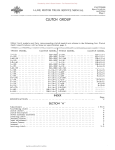
FRONT AXLE Specifications covering IHC F-553-A Front Axle for Truck Models R-lS53 to RF-194.inclusive
and the Timken FE-900 Front Axle for Truck Models R-190 to RF-Z10 inclusive are listed in
the following chart:
FRONT AXLE SPE CIFICA TIONS
. FRONT AXLE MODEL
FE-900
F-553-A
1 ~ 1/s11
I-liz" Knuckle Pin Diameter
1-15/16"
1-39/6411 (large end) Knuckle Pin Length
4-Z1/3Z"
9-314 11 Ball
Roller Tie Rod Diameter
Knuckle Pin Thrust Bearing Type
Steering Knuckle Spindle Diameter:
At Inner Bearing Diameter
z-1/16"
Z - 3/s"
1-5/16"
1-3/4"
3- 3/Sxz -1/4"
4x3- 9/16"
Alignment Data:
*A-Center of Steering Arm Ball
to level of Spring Pad
4-1/16 11
4-3/4"
*B -Spring Centers
31-1/8"
31-1/s"
*E-Camber at Rim (D.egrees)
10
10
*F -Knuc~le Pin Inclination (Degrees)
40
5-l/z o
ZO to 3 0
ZO to 3 0
At Outer Bearing Diameter
I-Beam Section
.
*G-Caster (Degrees)
*H-Center of Steering Arm Ball to Center Line of I-Beam *MN -Toe-In (Measured from Thread Centers with Cambers and Caster according to Specifications) * Key letters
. ...
,.
......... .
l/16-1/s"
.
~
.. . . ..
. .. . . .. . .
1/16-1/sl1
refer to illustrations appearing under Axle-Front, Section A, page 3, L-Line.
CTS Il-MARCH 1953 (Supplement.l pages for CTS·lll. PRINTED IN UNITE.D STATES OF' AMERICA.
Donated by John & Susan Hansen - For Personal Use Only
Donated by John & Susan Hansen - For Personal Use Only
AXLE-FRONT
Specifications
and Index
Page 1 L-LINE MOTOR TRUCK SERVICE MANUAL
FRONT AXLE GROUP Motor truck models and their corresponding front axle models are shown in the following list.
Axle model specifications will be found on page 2 of this section.
TRUCK MODEL
AXLE MODEL
AXLE MODEL TRUCK MODEL
L-lIO . • . . . • . . . • . . . . . . . . . • • . .
L-120 . . . • . . . • • . . ' • • . • . • . . . . . .
LM-120 . . . . . • • • . • . • . . . . . • . • . .
L-130 . • . . . . . . . . • . • • • • . • . . • • .
LB-140 . . . . . . . . . . . • . • . . • • . . • •
L-150 • . . . . . . . • • . . . • . . . . . . . . .
L-153 . • • . . • • . . . . • . . . . . . . . . • .
LM-150 • . . . . . . . . . . • . . . • • . . . • .
L-l60 . . . . • • . . • . . . . . • . . . • . . . .
L-163 • . . . . . . . . . . . . . . . . . . • . . .
L-164 . . . . . . • . . . • . . . . . . • • . . . •
L-165 • . • . • • . . . . . . . • . . . • • . . . •
LC-l60 . . . . . . . . . . . . . . . • . . . • . .
L-170 . . • . . . . • . . . . . . . . . . • . . . •
L-173 . . . . . . • . . . • . . • • . . . • . . . .
L-174 • . . . . . • . . . . • . . . . . . . . . • .
L-175 . • . • . . . . . . . • • . . . . . . . . . .
LF-170 • • • . . . . • • • • . • . • . • • • . . •
L-IBO . • . . • • • . . . • . . . . . . • . • . • .
L-IB3 • . . • . . • • . . . • • . . . . . . . . . .
F-160
F-170
F-l70
F-170
F ... 170
F-2S0
F-2S0
F-270
F-360
F-360
F-360
F-360
F-360
F-5S0
F-5S0
F-5S0
F-5S0
F-5S0
L-IS4 • . . . . • • . • . . . • . • . . • • • • • •
L-lS5 • . . • • . . • • . . . • . . . • . • . • • •
LC-lS0. • • • . . . . . • • • . • • • . • . . . .
L-190 . • • . . • • • . . • . . . . • • . • . . . •
L-193 . . . • • . . • • . . . . . • . . • . . . . •
L-194 . . . • • . . . . . . . . . . . . . . • . "
L-195.. • . . . . . . • • • . . • . . . • . • •.
LC-l90 . . . • . . . . . . . . • . . . . • . . . .
LF-190 . . . • . . . • . . . • . . • • . . . . . •
L-200 . • . • . . . . . . • . . . . . • . . . • • .
L-204.. • . . . . • • . . • . . . . . . • • . ••
L-205 • . . . • • • . • • . • . • . . • . • • • • •
LC-200 • . • . . . • . . . • . . . " • • . . . . .
L-210 . . • • . . • . • • . . • . . . • . . . . . .
LF-210 . . . . . . . . . • . . • • • . . • • . • •
L-220 • • . . • • . . . . . . . . . • • • . . • • •
L-225 . . • • . . . • • • . • . . . . • . • . . . •
LF-220 . . . . . . • • • • . • • • . . • • . . . •
F-5BO L-230 • . • . . • • . • . • . • . • . . . • • . . .
F-5BO LF-230 • . • . . . • . . . . . . . . • • . . • • .
INDEX
F-5BO F-5BO F-5S0 F-553 F-553 F-553 F-553 F-553 F-553 F-653 F-653 F-653 F-653 F-751 F-751 F-750 F-750 Page 2
Front axle specifications . . . . . . . . . . . . • . • . • . . . . . . . • . . • • . . . • .
SECTION "A" - F-160, F-170, FRONT AXLES
.Ax.le caster ........................
Knuckle pin inclination . • • • . • • • . . . • . . . • . • . . . • . . . . • • . . • . . . . • • . . . . . . •
Refitting knuckle pin bushings. • . . • . . . • • . . • • . . . • . . • . . . . . . . . • • • . • . • . • . •
Steering knuckle pins and bearings . • . . • • . • • . . . • . . • . . . • • • . . • • . • . . . . . • . •
Steering knuckle stop screws. . . • . . . • . . . . . . . • . . . . . . . . . . . • . . . . • . . . • . . .
Tie rod . . . • • . . . . • • . . • . • . • . . . . . . • . . • • . . . . • . . • • . . . . • . . . . . . . . . • .
Whee I alignment. . . . . • . . . • . • . • • . . • • . . • • . . • . . . • . • . • • • . . . • • . • • • . . • •
Whee 1 cambe r . . • . . . . . . . . . . . . . . . . . • . • • • . • . . • • . . . . . . . • . . . . • • . . • . .
Wheel toe-in . • . . . . . . . . • . . . . . . . . . . . . . . • • . . • • . . . • • . . . • . . • . • .
II
•
..
..
..
..
..
..
..
..
..
..
..
..
•
..
..
..
..
..
..
..
..
..
..
..
..
..
..
..
..
..
..
..
..
..
..
..
•
•
.
.
.
.
.
•
•
.
.
.
.
.
.
.
.
•
.
.
•
.
.
•
.
.
.
3
3
1, 2 1
2
2
2
3
2, 3 SECTION "B" - F-270, F-280, F-360, F-580, F-553, F-653, F-750, F-751, FRONT AXLES Axle caster. . • . . . . . . . . . . . . . . . . . . . • . . . • • . . . .
Knuckle pin inc lination . • • . . • . . . . • • . . . . . . . . . . . .
Refitting knuckle pin bushings. . . . . . . . . • . . . . . . . . . .
Steering knuckle pins and bearings . . . . . . . • . • . . . . • .
Steering knuckle stop screws . . • . . . . • . . . • . . . . . . . "
Tie rod. . . . • . . • . • . . . . . • . . . . . . . • . • . . • . . . . • .
Whe e I alignment . . . . . . . . . . . . . . • • . . . . • . . • . . . •
Wheel Gamber. . • • . . . . . • • . • • . . • • . . . • . . . . • . . .
Wheel toe-in. • . . • . • . . . . . . • . • . . . . • • • . • . . . . • .
.
.
.
•
•
.
.
•
.
.
.
.
.
.
.
.
.
•
.
.
.
.
.
•
•
.
.
•
.
.
.
.
.
•
.
•
.
.
.
•
.
.
•
•
.
•
.
.
.
.
.
•
•
.
.
.
•
.
.
.
.
.
•
.
.
.
.
.
•
.
.
•
.
.
.
•
.
.
.
•
.
.
.
.
.
.
.
•
.
•
.
.
.
.
•
.
•
.
.
.
.
.
.
•
.
.
.
•
•
.
.
.
.
.
•
•
.
.
.
.
.
•
.
•
.
.
.
.
.
.
.
.
.
.
•
.
•
.
.
.
•
.
.
.
.
•
•
.
•
.
.
.
•
4
4
I
1
2, 3 3
3
3, 4 3
SECTION "C" Suggested wheel alignment trouble shooting chart.
PRINTED IN UNITED 5TA,T£S OF "MERle'"
I
Donated by John & Susan Hansen - For Personal Use Only
~.w>
t"II ~. t<
OQ('I):><
N::t!t::I
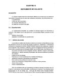
FRONT AXLE SPECIFICATIONS
FRONT AXLE MODEL
I"l
p;:;o
00
F-I60
F-I70
-
Tie Rod Dianneter
3/4"
Knuckle Pin Diannete r
.861
Knuckle Pin Dianneter 0.5.
.876
.876
5-7116 f1
5-7/16 1t
3/4"
.861
F-280
F-360
F-580
F-553
F-653
F-750
F-751
I"
111
I"
1-1/8 11
1-1/8"
1-1/4 11
1-1/2"
1-1/2"
1.110
1.110
1.110
1.234
1.234
1.484
1.359
1.359
F-270
Knuckle Pin Thrust Bear
ing Type
Steering Knuckle Spindle
Dianneter:
At Inner Bearing
Dianneter
At Outer Bearing
Dianneter
I-Beann Section
Alignnnent Data:
A-Center of Steering
Arnn Ball To Level
of Spring Pad
B-Spring Centers
E-Cannber At Rinn
(Degrees)
F-Knuckle Pin Inclina
tion
G-Caster - Degree
H-Center of Steering
Arnn Ball to Center
Line of I-Beann
MN-Toe-In (Measured
Fronn Tread Centers
With C annbe rand
Caster According to
Specifications
::l
til
Z
1--3
----
r-
Knuckle Pin Dianneter 0.5.
Knuckle Pin Length
I
III I:tj
6-1/4"
6-1/4"
6-1/4"
6-3/4"
7-21/3211
7-1/2"
9-5/8 11
9-5/8 11
tz
[Tl
Ball
1.3125
.8122
2-1/4"
x
1-11/16"
Roller
Roller
Roller
Roller
Roller
Roller
Roller
Roller
125
1.562
1.562
1.562
1. 750
2.000
2.125
2.250
2.250
.8122
.937
.937
.937
1.000
1.375
1.750
2-7/8"
x
2"
3"
x
2-1/81t
1.1875
3-3/8 1t
x
2-1/4"
3-13/16 11 x
2-1/211 3-3/4"
x
2-3/4"
1. 750
3-3/411
x
2-3/411
Ball
1
2-7/16" 2-11/16 11
x
x
1-13/16"
1-7/8"
3-1/411
x
2-1/8"
s:
~::u -l
::u
C
n
A
(J)
[Tl
::u
<
()
2_5/8"
2-29/32"
28-1/16" 3T':':7/8"
1°
1°
1°
1° 40
2 to 3 0
4°
2 to 3 0
40
2 to 3°
40
2 to 3 0
40 2 to 3 0 2-17132"
2-1/ 2"
0
0
0
0
0
0
0
1/8 to
3116"
1/16 to
1/8"
III 6 to
1/8"
1116 to
1/8 11
III 6 to
1/8"
III 6 to
118"
1116 to
1/8"
1/16 to
1/8"
1/16 to
1/8 11
20
20
1°
4°
2 to 3 0
40
2 to 3 0
118 to
3/16 11
4-27132" 4-27132"
31-118 11
31-118"
3-1/411
31-718"
2-5/8"
28"
·17/32'
4-1/16 11
31-1/8"
2-29/3211
31-7/8"
2-5/8"
28"
4-9/3211
31-1/8"
10
40 2 to 3 0 10
4° 2 to 3 0 10
4° 2 to 3 0 [Tl
s:
»z c
»
r
Donated by John & Susan Hansen - For Personal Use Only
L-UNE MOTOR TRUCK SERVICE MANUAL
AXLE-FRONT
Section A
Page 1
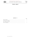
FRONT AXLES F·160, F-170
steering Knuckle Pins and Bearings
(See Figs. 1 and 2) Steering knuckle thrus t bearings, located
between knuckles and lower faces· of I-beam,
support the entire front end load. The end play
must be kept within proper limits to prevent
excessive wear. The use of spacing washers
to correct this condition is described in sub
sequent paragraphs. A tapered draw key with
nut and lockwasher hold knuckle pin rigidly in
end of I-beam.
Shock absorber
Expansion plug
Steering knuckle
The draw keys should be inspected occa
sionally to assure their being tight. 1£ one
becomes loosened, knuckle pin hole as well as
draw key hole will become worn and necessitate
replacing or machining of I-beam.
Steering knuckle pins and bushings are
available in sets to facilitate replacement
service.
Oversize steering knuckle pins are avail
able for use if the I-beam hole has been worn.
Installation of oversize pins necessitate ream
ing hole in the I-beam and bushings to the new
diameter.
Bronze bushings are used in steering
knuckle at upper and lower knuckle pin holes.
Seals at top and bottom consist of expansion
plugs pressed into steering knuckle.
Removal of expansion plugs can be readily
accomplished by drilling a 174" hole through
one of the plugs. Remove knuckle pin draw
key. Insert a punch in hole in expansion plug
and drive pin against opposite plug, forcing it
from its recess. Reverse direction of pin trav
el and force out drilled expansion plug.
A-22487
Fig. 2,
Refitting Steering Knuckle Pin Bushings
After ascertaining that steering knuckle
bushings require replacement, the following
procedure will be found efficient and helpful:
For service stations doing a large volume
of steering knuckle bushing service work,
there is a special set of installing arbors and
burnishing tools available. Reamers are not
necessary with this equipment.
1. Remove hub caps and grease caps.
2. Remove spindle nut cotter keys and spindle
nuts.
3. Remove wheels, inner bearings, and grease
retainers from spindles.
4. Remove dirt shield screws and shields.
5. Remove bolts holding brake backing plate
assemblies to steering knuckles.
Lay
assemblies back over ends of axle I-beams.
~~""':::"-r-- King pin
6. Remove tapered draw keys holding knuckle
pins.
A-22203
Fig. I
PRINT[O IN UNITED STATES Of' """ERICA
7. Remove expansion plugs f:rom top and bot
tom of steering knuckles.
8. Drive out knuckle pins.
Donated by John & Susan Hansen - For Personal Use Only
AXLE-FRONT
Section A
Page 2
L-UNE MOTOR TRUCK SERVICE MANUAL
9. Remove steering knuckles, thrus t bearings,
and any spacer shims present.
10. Clean all parts thoroughly in kerosene or
Stoddard Solvent.
11. Remove old bushings, using an arbor or
drift.
12. Install new bushings, with the grease holes
lined up with the lubricating holes in the
steering knuckles. Use an arbor press or
vise for forcing the new bushings into
place, piloting with a proper size arbor.
13. Line-ream new bushings.
Use either
special burnishing equipment or a reamer
equipped to pilot in one bushing while
reaming the other or a reamer long enough
to ream both bushings at the same time.
14. Install steering knuckles, thrust bearings,
spacer shims as required, and knuckle
pins.
15. Install knuckle pin draw key and tighten
securely. NOTE: Draw key nut and lock
washer should be located on front side of
axle.
Ball
seat A-22204
Fig. 3 - Details of tie rod end.
Tie R od (Fig. 3)
Tie rod is of three-piece construction,
consisting of two rod end assemblies. Rod is
threaded into ends and locked with clamp bolts.
Right and left-hand threads are provided to
facilitate toe-in adjustment. The rod ends are
self-adjusting and require no attention in serv
ice other than periodic lubrication and occa
sional inspection to see that ball studs are tight
in steering knuckle arms.
Proper adjustment can be effected by:
16. Insert expansion plugs in top and bottom
of steering kn\lckles. Expand into recess
by striking with a hammer.
17. Place brake backing plates in position and
install bolts. Tighten bolts securely.
1. Remove cotter key.
2. Tighten adjusting plug until it "bottoms"
or is snug.
18. Install dirt shields and holding screws.
3. Loosen adjusting plug to the nearest cotter
keyhole (not over 1/4 turn).
19. Clean and repack front wheel bearings.
4. Install new cotter key.
20. Install new grease seals.
NOTE: Always check and correct toe-in
of front wheels after any adjustment of tie-rod
ends.
21. Install wheels and spindle nuts. Rotate
wheel by hand while tightening nut until
drag or bind is felt. Back off nut to first
cas tellation and ins tall ~ cotter key.
22. Install grease caps and hUb caps.
23. Lubricate steering knuckle bushings.
Front Wheel Alignment
Front wheels mustbe kept inproper align':'
ment in order to assure ease of steering and
satisfactory tire life.
Important factors of
front wheel alignment are: Toe-in, camber
and axle caster.
24. Check and correct toe-in of wheels.
Steering Knuckle Stop Screws
Adjustable stop screws in steering knuckle
limit movement of front wheels when turning
and prevent tires from rubbing against nearest
point on chassis and to prevent steering gear
from bottoming. These screws should be ad
justed so there will be ample clearance between
front tires and nearest point on chassis when
wheels are turned to extreme right or left under
any conditions. NOTE: This should be checked
when tire size is changed.
These points should be checked occa
sionally to guard against excessive tire wear.
Wheel Toe-In (Fig. 4)
Front-wheel toe-in is the setting of front
wheels so that they are closer together at the
front of the axle than at the rear.
Incorrect toe-in of front wheels will result
in ra~id tire wear. Excessive toe-in will pro
duce a scuffing or "feather-edge" at the inside
edge of the tire tread. Toe-out will produce a
like wear but at the outside of the tire tread.
Donated by John & Susan Hansen - For Personal Use Only
AXLE-FRONT
Section A
Page 3
L-UNE MOTOR TRUCK SERVICE MANUAL
C
"Positive" camber is an outward tilt or
inclination of the wheel at the top.
TREAD
~-
N
r
BI
"""
I
,
,
"- ./
~
Axle Caster (Fig. 6)
f¢,OF STEERING
ARM BALL ,..~
~
f-.
r
,
IJ
-
~
-
1\T
,
-
The purpose of caster is to provide stabil
ity of steering.
,
~D~TO~KING PI~! '
M
Fig.
Caster is the amount of backward tilt at
the top of the steering knuckle pin. When the
top of the knuckle pin is tilted to the rear, the
caster is positive. When the top of the knuckle
pin is tilted to the front, the caster is negative.
,
'\<tOF AXLE~
"Negative" or "reverse" camber is an
ward tilt of the wheel at the top.
./
G- CASTER
I
A-22202
ANGLE
It
Follow instructions of Tool Equipment
Manufacturer for checking and correction of
toe-in.
NOTE: Always recheck toe-in after any
change in caster or camber angles, or after
any alteration in tie-rod end adjustment.
Wheel Camber (Fig. 5)
Front-wheel camber is the inclination of
the wheel from a vertical plane.
4 OF
KING PIN
E-CAM BE.R ANGLE.
VERTICAL LINE
A-22199
VERTICAL LINE
Fig. 6
1jF- KING PIN INCLINATION
"
-e-----r-'
~
A
t
'LEVEL OF
<t
SPRING PAD
STEERI NG ARM BALL
iHoFTIRE
Fig. 5
F>RINTEO IN UNITEO STATES OF' AMERICA
Tapered wedge plates are available for use
in altering the caster angle. They are to be
installed between the springs and axle spring
seats.
Installation with the thick end toward the
rear will produce increased caster. If in
s talled with thick end toward the front, will
decrease caster.
Knuckle Pin Inclination (Fig. 5)
A-22200
The angle which the kingpin makes with the
vertical is known as kingpin inclination.
Donated by John & Susan Hansen - For Personal Use Only
Donated by John & Susan Hansen - For Personal Use Only
L-LINE MOTOR TRUCK SERVICE MANUAL
AXLE-FRONT
Section B
Page 1
FRONT AXLES
F-270, F-280, F-360, f-580, F-553, F-653, F-750, F-751
Steering Knuckle Pins and Bearings
(See Figs. 1 and 2)
Steering knuckle thrust bearings, located
between knuckles and lower faces of I-beam,
support the entire front end load. The end play
must be kept within proper limits to prevent
excessive wear. The use of spacing washers
to correct this condition is described in sub
sequent paragraphs. A tapered draw key with
nut and lockwasher hold knuckle pin rigidly in
end of I-beam.
The draw keys should be inspected occa
sionally to assure their being tight. If one be
comes loosened, knuckle pin hole as well as
draw key hole will become worn and necessitate
replacing of I-beam.
Steering knuckle pins and bushings are
available in sets to facilitate replacement
service.
Bronze bushings are used in steering
knuckle at upper and lower knuckle pin holes.
Seals at top and bottom consist of gasket and
plate, held in position by flat head screws and
lockwashers.
Fig. 2 - Showing details of relay lever, relay
I ink and drag I ink.
2. Remove spindle nut cotter keys and spindle
nuts.
Spacing washer
3, Remove wheels,
inner bearings,
grease retainers from spindles.
and
4. Remove dirt shield screws and shields.
5. Remove bolts holding brake backing plate
assemblies to steering knuckles.
6. Remove tapered draw keys holding knuckle
pins.
7. Remove caps from top and bottom of steer
ing knuckles.
A·22542
Fig. I
Refitting Steering Knuckle Pin Bushings
For service stations doing a large volume
of steering knuckle bushing service work, there
is a special set of installing arbors and bur
nishing tools available. Reamers are not nec
essary with this equipment.
After ascertaining that steering knuckle
bushings require replacement, the following
procedure will be found efficient and helpful:
1. Remove hub caps and grease caps.
PRINTEO IN UI'(IT£O 5TA,TES OF' AMERICA
8. Drive out knuckle pins.
9. Remove steering knuckles, thrustbearings,
and spacer shims.
10. Glean all parts thoroughly in kerosene or
Stoddard Solvent.
11. Remove old bushings, using an arbor or
drift.
12. Install new bushings, with the grease holes
lined up with the lubricating holes in the
steering knuckles. Use an arbor press or
vise for forcing the new bUShings into
place, piloting with a proper size arbor.
Donated by John & Susan Hansen - For Personal Use Only
AXLE-FRONT
Section B Page 2
L-UNE MOTOR TRUCK SERVICE MANUAL
13. Line-ream new bushings. Use either a
reamer equipped to pilot in one bushing
while reaming the other or a reamer long
enough to ream both bushings at the same
time.
14. Ins tall steering knuckles. thrus t bearings,
spacer shims as required, and knuckle
pins.
20. Install new grease seals.
21. Install wheels, and spindle nuts. Rotate
wheel by hand while tightening nut until
drag or bind is felt. Back off nut to first
castellation and install new cotter key.
22. Install grease caps and hub caps.
23. Lubricate steering knuckle bushings.
15. Install knuckle pin draw key and tighten
securely.
16. Replace caps on top and bottom of steering
knuckles.
17. Place brake backing plates in pos ition and
install bolts. Tighten bolts securely.
18. Install dirt shields and holding screws.
19. Clean and repack front wheel bearings.
24. Check and correct toe-in of wheels.
Steering Knuckle Stop Screws
Adjustable stop screws in steering knuckles
limit movement of front wheels when turning
and prevent tires from rubbing against nearest
point on chassis and prevent steering gear from
bottoming. These screws should be adjusted
so there will be ample clearance between front
tires and nearest point on chassis when wheels
_ - - - - Lubricator
Relay lever
J..iF.-"-----Relay lever bracket
and shaft assembly
Relay link
stud ball
Frame side
rail
Drag link
stud ball
Steering gear
arm
Lubricator --lIo-<!
Lubricators
Drag link
A·21748
Fig. 3 - Front axle linkage and steering gear for L-190 Series and up.
Donated by John & Susan Hansen - For Personal Use Only
AXLE-FRONT
Section B
Page 3
L-UNE MOTOR TRUCK SERVICE MANUAL
are turned to extreme right or left under any
conditions.
NOTE:
This should always be
checked when tire size is changed.
satisfactory tire life.
Important factors of
front wheel alignment are: Toe-in, camber
and axle caster.
Linkage for Models L-190 and Up
(Figs. 2 and 3)
These points should be checked occasion
ally to guard against excessive tire wear.
Figs. 2 and 3 illustrate front axle linkage
with the steering gear for models L-l90 series
and up. In order to maintain the proper degree
of angle on steering column for best riding and
driving comfort, the relay lever assembly is
used.
C
N
r .......
Tie Rod (Figs. 4 and 5)
Tie rod is of three-piece construction,
consisting of two rod end assemblies and tube.
Rod is threaded into ends and locked with clamp
bolts. Right and left-hand threads are provided
to facilitate toe-in adjustment. The rod ends
are self-adjusting and requir.e no attention in
service other than periodic lubrication and
occasional inspection to see that ball studs are
tight in steering knuckle arms.
,...
-
~
.
I--
I
I ,
"- l/
Cover
B
If~OF STEERI 'JG
ARM BA Ll r--~
hi
,. '
..
T\
r
"'"
'
T
TI
'\q;OF AXLE
l
,
~D<tTO<tKING PI~ ' ./
M
Felt
TREAD
I
A-22202
Wedge....",.-~~--t
Fig. 6
Wheel Toe-In (Fig. 6)
BaD seat
Tie rod assembly-Models F-270, F-280,
A·22528
Fig. ij
F-360.
-
Tie rod end
~-~
Front-wheel toe-in is the setting of front
wheels so that they are closer together at the
front of the axle than at the rear.
Incorrect toe-in of front wheels will re
sult in rapid tire wear. Excessive toe-in will
produce a scuffing or IIfeather-edge" at the in
side edge of the tire tread. Toe-out will pro
duce a like wear but at the outside of the tire
tread.
Follow instructions of Tool Equipment
Manufacturer for checking and correction of
toe-in.
Washer Spring Cover
A·22551
Fig. 5 - Tie rod assembly - Models F-553, F-580,
F-653, F-750, F-751.
NOTE: Always recheck toe-in ~ any
change in caster or camber angles, or after
any alteration in tie-rod end adjustment.
Wheel Camber (Fig. 7)
Front Wheel Alignment
Front-wheel camber is the inclination of
the wheel from a vertical plane.
Frontwheels must be keptin proper align
ment in order to assure ease of steering and
"Positive" camber is an outward tilt or in
clination of the wheel at the top.
PRINTED IN UNIT£D STATES OF' AMERICA
Donated by John & Susan Hansen - For Personal Use Only
AXLE-FRONT
Section B
Page 4
L·LINE MOTOR TRUCK SERV1CE MANUAL
"Negative" or "reverse" camber is an ward tilt of the wheel at the top. ~r-G-CASTER _____T-'__
Axle Caster (Fig. 8)
ANGLE
Caster is the amount of backward tilt at
the top of the steering knuckle kingpin. When
the top of the knuckle pin is tilted to the rear,
the caster is positive. When the top of the
knuckle pin is tilted to the front, the caster is
negative.
The purpose of caster is to provide sta
bility of steering.
Tapered wedge plates are available for
use in altering the caster angle. They are to
be installed between the springs and axle
spring seats.
Installation of the tapered wedge with the
thick end toward the rear will produce increased
caster. If installed with thick end toward the
'front, decreased caster will result.
The angle which the kingpin makes with the
vertical is known as kingpin inclination.
E-CAMBE.R ANGLE.
VERTICAL LINE
1jF- KING PIN INCLINATION
[A
t
'LEVEL OF
<t
SPRING PAD
STEERING ARM BALL
OF TIRE
Fig. 7
4 OF
KING PIN
VERTICAL LINE
A-22199
Fig. 8
Knuckle Pin Inclination (Fig. 7)
'.
TAPERED
WEDGE
A·22200
Donated by John & Susan Hansen - For Personal Use Only
L-LINE MOTOR TRUCK SERVICE MANUAL
AXLE-FRONT
Section C
Page I
SUGGESTED WHEEL ALIGNMENT TROUBLE SHOOTING CHART Remember that all alignment angles are so
closely related that any change of one will auto
matically change the others. Because of this
fact, it will probably be found that there is more
than one cause for the complaint. The following
COMPLAINT
(1)
Shimmy
(Generally exists at speeds below
30 miles per hour.)
list is not all-encompassing but is representative
of the more common causes of difficulty en
countered in wheel and axle alignment and should
prove of value in locating and correcting com
plaints on steering or tire wear,
POSSIBLE CAUSE
(a) Tire pressure incorrect. (b) Tires of unequal size or weight. (c) Wheel bearings loose. (d) Steering arms loose. (e) Steering gear loose. ef) Too much caster. (g) Drag link ends loose. (h) Drag link springs weak or broken. (i ) Spring shackles loose. (j) Kingpins and bushings worn. (k) Tie-rod ends loose. (a)
(b)
Tire and wheel assemblies out of balance.
Shock absorbers ineffective.
(a)
(b)
(c)
(n)
(0)
(p)
(q)
(1' )
(s)
(t)
(u)
Tire pressure incorrect.
Tires of unequal size.
Bent spindle.
Wheel bearings loose.
Kingpins and bushings worn.
Kingpins bent.
Kingpins tight.
Pitman arm loose.
Steering gear assembly too tight or too loose.
Too little caster.
Too much or too little camber.
Too much or too little toe-in.
Drag link ends tight.
Drag link springs weak or broken.
Tie-rod ends too tight or too loose.
Front axle bent.
Front axle shifted.
Springs broken.
Rear axle shifted.
Rear axle housing bent.
Frame diamond-shaped.
(4) Hard Steering
(a)
(b)
(c)
(d)
(e)
(f)
Tire pressure low.
Wheel spindle bent.
Kingpin assembly poor fit.
Steering assembly too tight.
Tie-rod ends tight.
Gaster excessive.
(5) Uneven Tire Wea,r
(a)
(b)
(c)
(d)
(e)
(f)
(g)
Tire pressure low.
Excessive camber.
Wheels out of balance.
Tires overloaded.
Eccentric wheels or rims.
Gaster incorrect.
Toe-in incorrect.
(2)
High-Speed Wheel Tramp
(Generally e xists at speeds above
35 miles per hour.)
(3)
Wander or Weave
(d)
(e)
(f)
(g)
(h)
(i)
(j)
(k)
(1 )
(m)
PRINTED IN UNITED STATES OF AM[FlICA
Donated by John & Susan Hansen - For Personal Use Only