1
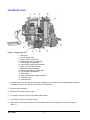
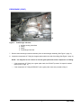
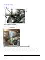
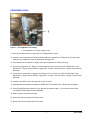
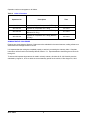
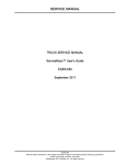
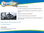
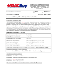
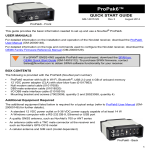
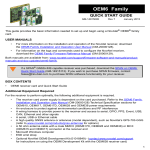
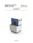
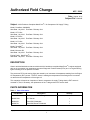
Authorized Field Change
AFC 11912
Date: August, 2011
Subject File: ENGINE
Subject: 2010 Emissions Compliant MaxxForce® 7 Air Compressor Oil Supply T-fitting
Model: DuraStar® 4300M4X2
Start Date: July 2010 End Date: February 2011
Model: CE C Bus
Start Date: July 2010
End Date: February 2011
Model: CE S Bus
Start Date: July 2010
End Date: February 2011
Model: HC C Bus
Start Date: July 2010
End Date: February 2011
Model: TerraStar®
Start Date: July 2010
End Date: February 2011
Model: Monaco® RV
Start Date: July 2010
End Date: February 2011
Engine Family: MaxxForce® 7
Start Date: July 2010 End Date: February 2011
DESCRIPTION
Certain vehicles listed above that were built with 2010 emissions-compliant MaxxForce® 7 engines equipped
with an air compressor may experience erroneous Diagnostic Trouble Codes (DTCs) and / or engine warning
lights indicating a low oil pressure condition.
The erroneous DTCs and warning lights are caused by an inaccurate oil temperature reading from the Engine
Oil Temperature (EOT) sensor. The EOT sensor is reading the temperature of the fitting that it is mounted
on rather than the temperature of the engine oil.
This campaign will require an inspection of the air compressor oil supply T-fitting that the EOT sensor is
mounted on; and, if necessary, the replacement of the T-fitting and the EOT sensor itself.
PARTS INFORMATION
Table 1
Parts Information
Part Number
Description
Quantity
1884439C92
Air Compressor Oil T-Fitting
1
1836537C91
EOT Sensor
1
1889613C1
Tube ASM, Wastegate
1
1886507C1
Tube ASM, Boost to Solenoid
1
Copyright © 2011 Navistar, Inc. All rights reserved. All marks are trademarks of their respective owners.
1
PARTS INFORMATION (CONT.)
Table 1
Parts Information (cont.)
Part Number
Description
Quantity
1886508C1
Tube, Relief to Duct
1
1897455C92
Kit, Turbo Mounting
1
1883660C1
Gasket, V-Band Turbo
2
PROCEDURE
WARNING – To prevent vehicle damage, personal injury, or death, park the vehicle on a flat,
level surface. Make sure the engine ignition is in the off position, and the transmission is in the
neutral or park position, if the vehicle is equipped with an automatic transmission. Set the parking
brake, block the wheels to prevent the vehicle from moving in both directions, and disconnect the
batteries at the negative terminal before doing any service procedures on the vehicle.
WARNING – To prevent personal injury or death, remove ground cable from negative terminal
of main battery before disconnecting electrical components. Always connect ground cable last.
WARNING – To prevent personal injury or death, make sure that the engine has cooled before
removing components.
WARNING – To prevent personal injury or death, always wear safe eye protection when
performing vehicle maintenance.
WARNING – To prevent personal injury or death, do not let engine fluids stay on your skin.
Clean skin and nails using hand cleaner and wash with soap and water. Wash or discard clothing
and rags contaminated with engine fluids.
AFC–11912
2
PROCEDURE (CONT.)
This procedure covers several vehicle models. The procedures for accessing the engine vary according
to the vehicle being serviced.
•
Monaco® RV vehicles – When instructed, refer to the appropriate Monaco® service manual to gain access
to the top of the engine.
•
International® vehicles – When instructed, refer to the appropriate service manual on the ISIS® system
to gain access to the top of the engine. (Some components may require removal, such as the right
inner-fender splash shield and the engine cover.)
The air compressor oil T-fitting is located under the Engine Oil Temperature (EOT) sensor, which is located
under the turbocharger crossover tube (See Figure 1, page 4 ).
Inspection of the T-fitting requires removal of the turbocharger inlet air duct assembly (See Figure 1, page 4 ).
Depending on the vehicle, this may require removal of the following peripheral components.
•
inner-fender splash shield
•
air filter housing
•
air filter outlet ducting
Removal of the T-fitting requires removal of the turbocharger assemblies which will require access to the top
and top-rear of the engine. Depending on the vehicle, this may require removal of the following peripheral
components in addition to those removed for inspection.
•
inner-fender splash shield
•
Electronic Control Module (ECM)
•
air filter housing
•
air filter housing mounting bracket
•
engine wire harness cover
•
shifter assembly (reposition)
•
passenger seat
•
park brake lever assembly (reposition)
•
engine cover
3
AFC–11912
PROCEDURE (CONT.)
Figure 1
Engine top view
1. EGR valve
2. Inlet Air Heater (IAH)
3. Engine Throttle Valve (ETV)
4. Turbocharger inlet duct assembly
5. Turbocharger oil supply tube
6. Low-pressure turbocharger assembly
7. Pump cover heat shield (right)
8. Right exhaust tube assembly
9. Exhaust turbocharger inlet manifold
10. Left exhaust tube assembly
11. EGR cooler
12. High-pressure turbocharger assembly
13. Crossover tube
14. Manifold mixer
1. Park the vehicle on a flat surface, shift the transmission to park or neutral, set the parking brake, and block
the wheels to prevent the vehicle from moving in both directions.
2. Raise the hood assembly.
3. Disconnect the battery ground cable.
4. If necessary, remove the right inner fender splash shield.
5. If necessary, remove the air filter housing.
6. Disconnect or remove the air filter housing inlet elbow from the turbocharger inlet duct (See Figure 2,
page 5 ).
AFC–11912
4
PROCEDURE (CONT.)
Figure 2
Turbocharger inlet duct
1.
2.
3.
4.
Air filter housing inlet elbow
Clamp
Clamp
Turbocharger inlet duct
7. Remove the turbocharger inlet duct assembly from the turbocharger assembly (See Figure 2, page 5 ).
8. Inspect the compressor oil T-fitting for the green paint mark on the side of the fitting (See Figure 3, page 6 ).
NOTE – You may have to use a mirror to view the green paint mark on the compressor oil T-fitting.
•
If the compressor oil T-fitting has a green paint mark, then DO NOT proceed. No repair is needed
(See Figure 4, page 6 ).
•
If the compressor oil T-fitting DOES NOT have a green paint mark, then proceed to Step 9.
5
AFC–11912
PROCEDURE (CONT.)
Figure 3
Compressor oil T-fitting
1. Turbocharger inlet
2. Compressor oil T-fitting
3. Crossover tube
Figure 4
Compressor oil T-fitting with green paint mark circled in yellow
9. Remove the dual turbochargers as outlined in EGES 4801, 2010 MaxxForce® 7 Engine Service Manual.
10. Disconnect the air compressor oil supply tube from the air compressor oil T-fitting (See Figure 5, page 7 ).
AFC–11912
6
PROCEDURE (CONT.)
Figure 5
Air compressor oil T-fitting
1. Air compressor oil T-fitting supply line nut.
11. Remove and discard the old compressor oil T-fitting and EOT sensor.
12. Install the new compressor oil T-fitting and hand start the compressor oil T-fitting to the oil cooler base
slightly snug for alignment of the air compressor oil supply line.
13. Hand start the air compressor oil supply line to the compressor oil T-fitting until snug.
14. Torque the compressor oil T-fitting to oil cooler base at 25 N·m (18 lbf·ft). Refer to EGES 4801, 2010
MaxxForce® 7 Engine Service Manual - Appendix B - Torques - General Torque - Using a Torque Wrench
Extension.
15. Torque the air compressor oil supply line to fitting at 17 N·m (12.5 lbf·ft). Refer to EGES 4801, 2010
MaxxForce® 7 Engine Service Manual - Appendix B - Torques - General Torque - Using a Torque Wrench
Extension.
16. Install the new EOT sensor and torque to 18 N·m (13 lbf·ft).
17. Reinstall dual turbochargers as outlined in EGES 4801, 2010 MaxxForce® 7 Engine Service Manual.
18. Use an Engine Electronic Service Tool to clear the oil pressure codes. If you have any other codes
non-related, please diagnose them separately.
19. Start the engine and check for leaks.
20. Close the hood and remove the wheel chocks.
21. Return the service tools and the service parts.
7
AFC–11912
Operation number must appear on all claims.
Table 2
Labor Information
Description
Operation No.
Time
A40-11912-1
Inspection Only - Air Compressor Oil T-fitting
0.5 hours
A40-11912-3
Replace Air Compressor Oil T-fitting
3.4 hours
A40-11912-2
Inspection Only - Air Compressor Oil T-fitting
(Monaco® RV only)
0.7 hours
A40-11912-4
Replace Air Compressor Oil T-fitting (Monaco®
RV only)
4.4 hours
ADMINISTRATIVE PROCEDURE
Expense is to be charged to Warranty. Claims are to be submitted in the normal manner, making reference to
Authorized Field Change Number G-11912.
It is important that the coding be completed properly to assist in processing the warranty claim. Complete
instructions will be found in the Warranty Manual, Section 7–1. Special attention should be given to Items 39
through 44.
To assure this important improvement is made in a timely manner, all claims for G-11912 activity must be
submitted by August 31, 2012 or within the normal warranty period for the vehicle, if after August 31, 2012.
AFC–11912
8
9
AFC–11912