1
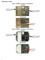
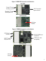
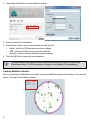
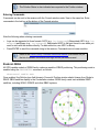
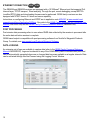
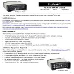
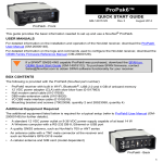
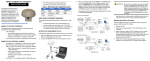
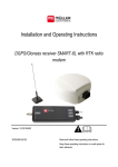
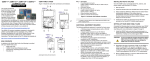
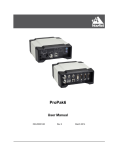
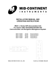
OEM6® Family QUICK START GUIDE GM-14915095 Rev 7 January 2015 This guide provides the basic information needed to set up and begin using a NovAtel® OEM6® family card. USER MANUALS • For more information on the installation and operation of the NovAtel receiver, download the OEM6 Family Installation and Operation User Manual (OM-20000128). • For information on the logs and commands used to configure the NovAtel receiver, download the OEM6 Family Firmware Reference Manual (OM-20000129). Both manuals are available from: www.novatel.com/support/firmware-software-and-manuals/productmanuals-and-doc-updates/oem6-family. If a SPAN® GNSS+INS capable receiver was purchased, download the SPAN on OEM6 Quick Start Guide (GM-14915112). If you wish to purchase SPAN firmware, contact [email protected] to purchase SPAN software functionality for your receiver. BOX CONTENTS • OEM6 receiver card and Quick Start Guide Additional Equipment Required For the receiver to perform optimally, the following additional equipment is required. • • • • • • • • • The receiver card power supply is dependent on the card purchased. Refer to the OEM6 Family Installation and Operation User Manual (OM-20000128) Technical Specification sections for OEM615, OEM617, OEM617D, OEM628 and OEM638 power requirements An enclosure to protect against environmental conditions and RF interference A wiring harness to provide power to the receiver and access to serial, GPIO, PPS, Event, USB, CAN, Ethernet and other signals A serial, USB or Ethernet cable A high quality GNSS antenna or antennas (model dependent), such as NovAtel’s GPS-703-GGG (refer to www.novatel.com/products/gnss-antennas for options) A 50 ohm antenna cable with a male MMCX (OEM617D, OEM628 and OEM638) or MCX (OEM615 and OEM617) connector at the receiver end Microsoft Windows computer ESD wrist strap Optional NovAtel OEM6 Development Kit (01018849) - (contact www.novatel.com/support for instructions on using the OEM6 Development Kit with the OEM638 receiver card) 1 OEM6 FAMILY CARDS Figure 1: OEM615 Connectors and Indicators TOP VIEW J101 RF signal IN/ LNA power OUT J1101 Power/data/ signal connector BOTTOM VIEW LED Status Indicator Figure 2: OEM617 Connectors and Indicators TOP VIEW J101 RF signal IN/ LNA power OUT J1101 Power/data/ signal connector BOTTOM VIEW LED Status Indicator 2 Figure 3: OEM617D Connectors and Indicators TOP VIEW Primary RF signal IN/LNA power OUT J1101 Power/data/ signal connector Secondary RF signal IN/LNA power OUT BOTTOM VIEW LED Status Indicator Figure 4: OEM628 Connectors and Indicators TOP VIEW J101 External Oscillator P1502 CAN/Ethernet connectors P1500 power, data and signaling J100 RF signal IN/ LNA power OUT BOTTOM VIEW LED Status Indicator 3 Figure 5: OEM638 Connectors and Indicators TOP VIEW J3201 Ethernet connector J4101 expansion header J302 External Oscillator J201 RF signal IN/ LNA power OUT P4001 power, data and signaling BOTTOM VIEW LED Status Indicator Refer to OEM6 Family Installation and Operation User Manual (OM-20000128) for installation instructions and technical specifications for the OEM6 family cards. NovAtel recommends tying floating input lines to ground. SETTING UP AN OEM6 FAMILY CARD Complete the following steps below to connect and power the OEM6 family card. When installing cards, ensure all standoffs are properly installed and the mounting location is level. The amount of board deflection (bow and twist) must not exceed 0.75%. For example, on the OEM615 which is 71 mm long and 46 mm wide, the deflection along the length must not exceed 0.53 mm and the deflection along the width must not exceed 0.34 mm. 1. Install the OEM6 family card and the wiring harness in a secure enclosure to reduce environmental exposure, RF interference, and protect against ESD. 4 If the necessary precautions against Electrostatic Discharge (ESD) are not followed, the OEM6 card may be damaged and the warranty voided. 2. Prepare the COM ports as necessary. For OEM628 and OEM638, COM1 is software configurable for RS-232 and RS-422. For OEM615, OEM617 and OEM617D, COM1 is LVTTL and requires a level-converter to communicate at RS-232/RS-422 levels. 3. Mount a GNSS antenna on a secure, stable structure with an unobstructed view of the sky from horizon to horizon. 4. Connect the GNSS antenna to the OEM6 family card with a 50 ohm coaxial cable. 5. Connect the receiver to a computer with a null modem cable, a USB or Ethernet cable if the harness permits. 6. Connect a power supply to the OEM6 family card. 7. Plug in and/or turn on the power supply. When the OEM6 family receiver is installed in a permanent location, it should be protected by a lightning protection device according to local building codes. Refer to OEM6 Family Installation and Operation User Manual (OM-20000128), Notices Chapter, Lightning Protection and Grounding Procedure section for details. Refer to OEM6 Family Installation and Operation User Manual (OM-20000128) for additional information. NOVATEL CONNECT™ Once installed, NovAtel Connect provides a graphical interface to establish communication, control and monitor the operation of your NovAtel receiver. A Microsoft Windows based computer with an RS-232 DB-9, Ethernet or USB port is required to use NovAtel Connect. NovAtel Connect is bundled with the NovAtel PC Utilities. Go to the Support page of our web site at www.novatel.com to access and download the most recent version of NovAtel’s PC Utilities. Detailed instructions for using NovAtel Connect are available from within the included Help or the .chm file bundled with the software. Establishing a New Receiver Connection To establish a new connection to the receiver, complete the following: 1. Launch NovAtel Connect from the Start menu folder specified during the installation process. The default location is Start | All Programs | NovAtel Connect. 5 2. Select New Connection from the Welcome window. 3. Enter a name for the connection. 4. Select Device Type to use to communicate from the drop list: • Serial - define the COM port and connection settings • USB - define the COM port and connection settings • Network - select a receiver and define network settings 5. Click the OK button to save the new connection. Detailed instructions for using NovAtel Connect are available from within the utility Help. Default baud rate of 115200 is preferred if a higher is not available. No handshaking. Tracking Satellites Indicator Once a connection is established, the number and type of satellites being tracked display in the upper left corner of Connect’s Constellation window. 6 The Solution Status is also indicated as computed in the Position window. Entering Commands Commands can be sent to the receiver with the Console window under View in the menu bar. Enter commands in the text box at the bottom of the Console window. Note the following when entering commands: • Logs can be requested in three formats: ASCII (e.g., log bestposa), Abbreviated ASCII (e.g., log bestpos) and Binary (e.g., log bestposb). Abbreviated ASCII is the best format to use when you want to work with the receiver directly. For data collection, use ASCII or Binary. • Press ENTER to send the command string to the receiver. Commands are not case sensitive. Refer to the OEM6 Family Firmware Reference Manual (OM-20000129) for the list of available commands and logs and the parameters used. ENABLING SBAS All GPS capable models of OEM6 family cards are capable of SBAS positioning. This positioning mode is enabled using the SBASCONTROL command, as follows: sbascontrol enable auto Once enabled, the Solution type field shown in Connect’s Position window should change from Single to SBAS. SBAS satellites display in the Constellation window. OEM6 family cards track available SBAS satellites, including WAAS, EGNOS and other SBAS systems. 7 ENABLING L-BAND 628 638 L-Band equipped receivers can achieve sub-metre position accuracy using correction data received from geostationary satellites. To use the L-Band corrections, an L-Band-capable receiver model and antenna are required (refer to our web site www.novatel.com/products/gnss-antennas for information on NovAtel L-Band-capable antennas) along with a subscription service. NovAtel CORRECT™ with PPP can use the following correction subscriptions: • TerraStar for land, airborne and near shore applications • Veripos Apex and Apex2 for marine applications Receivers must be powered and tracking an L-Band satellite prior to activating a subscription service. For more information on L-Band positioning: • Refer to a NovAtel Application Note: APN-061 NovAtel CORRECT with TerraStar, APN062 NovAtel CORRECT with Veripos or APN-051 Positioning Modes of Operation (service dependent) available from www.novatel.com/support/search/items/Application%20Note • Refer to the OEM6 Family Installation and Operation User Manual (OM-20000128) and/or the ProPak6 User Manual (OM-20000148) • Refer to the OEM6 Family Firmware Reference Manual (OM-20000129) for log and command details • Visit www.novatel.com/support and speak with a Customer Service representative • Visit www.novatel.com/products/novatel-correct LOG REAL-TIME KINEMATIC (RTK) POSITIONING For more base/rover configurations, search the key words “rover base” at www.novatel.com/support/search/. Corrections can be transmitted from a base station to a rover station to improve position accuracy to centimetre level. The base station is the GNSS receiver that is acting as the stationary reference. It has a known position and transmits correction messages to the rover station. The rover station is the GNSS receiver that does not know its exact position but which can receive correction messages from a base station to calculate differential GNSS positions. In most cases, a data link between the base station and rover station (two NovAtel receivers) is required in order to receive corrections. It is also possible to receive and use RTK corrections from established networks. SBAS and L-Band corrections can be acquired with one receiver and are exceptions to the base/rover concept, although neither are considered RTK positioning. Generally a link capable of data throughput at a rate of 19200 bits per second, and less than 4.0 s latency, is recommended. 8 Once the base and rover are set up, configure them for RTCA, RTCM, RTCMV3, CMR+ or CMR corrections. Below is an RTCA example (replace the latitude, longitude and height coordinates shown with those of the base): Base serialconfig com2 115200 n 8 1 n on interfacemode com2 none rtca off fix position latitude longitude height (enter your own lat, long and hgt values) log com2 rtcaobs2 ontime 1 log com2 rtcaref ontime 10 log com2 rtca1 ontime 5 (DGPS) Rover interfacemode com2 rtca none off RT-2® is NovAtel’s proprietary Real-Time Kinematic (RTK) solution. Optimal RTK performance is achieved when both the base and rovers are NovAtel products, however, RT-2 will operate with equipment from other manufacturers when using RTCM and CMR messaging. RT-2 is supported by GPS only and GPS+GLONASS OEM6 based models. For more base/rover configurations, search the key words “rover base” at www.novatel.com/support/search/. Refer to OEM6 Family Installation and Operation User Manual (OM-20000128) for additional information. 9 ETHERNET CONNECTION 628 638 The OEM628 and OEM638 receivers are equipped with a 10/100baseT Ethernet port that supports IPv4 Internet layer, TCP/IP transport, Telnet and ping. Through the port, remote debugging, accept MRTCA (modified RTCA) data and downloading firmware can be performed. OEM6 family receivers are also equipped with NTRIP Version 2.0 client and server capability. Instructions on configuring Ethernet and NTRIP are in application note APN-057 at www.novatel.com/ support/search/items/Application%20Note. Also refer to the OEM6 Family Installation and Operation User Manual (OM-20000128) and the OEM6 Family Firmware Reference Manual (OM20000129). POST PROCESSING Post-mission data processing refers to case where GNSS data collected by the receiver is processed after the entire data collection session is complete. OEM6 based output is compatible with post-processing software from NovAtel’s Waypoint® Products Group. For details, see www.novatel.com/Products/Waypoint Software. DATA LOGGING An extensive set of logs are available to capture data (refer to the OEM6 Family Firmware Reference Manual-OM20000129). Logs can be directed to any of the OEM6 family card’s communication ports and can be automatically generated when new or changed data becomes available or at regular intervals. Data can be collected through NovAtel Connect using the Logging Control Window. 10 ONBOARD MEMORY 638 The OEM638 contains 4 gigabytes of non-volatile flash memory for onboard data storage. Data can be logged to internal memory and downloaded for post-processing. Refer to the OEM6 Family Installation and Operation User Manual (OM-20000128) for details. Additional Functionality Refer to the OEM6 Family Installation and Operation User Manual (OM-20000128) for set up and installation instructions for CAN and External Oscillator functionality. Configuration Notes: 11 QUESTIONS OR COMMENTS For questions or comments regarding a OEM6 Family card, please contact NovAtel using one of these methods: Email: [email protected] Web: www.novatel.com Phone: 1-800-NOVATEL (U.S. and Canada) +1-403-295-4900 (International) Fax: 403-295-4901 Quick Start Guide - OEM6 Family Cards OEM6, Waypoint, NovAtel and RT-2 are registered trademarks of NovAtel Inc. NovAtel CORRECT, NovAtel Connect, OEM615, OEM617, OEM617D, OEM628 and OEM638 are trademarks of NovAtel Inc. All other brand names are trademarks of their respective holders. ©Copyright 2015 NovAtel Inc. All rights reserved. Printed in Canada on recycled paper. Recyclable. 12