1
SIXFORS SERVICE MANUAL
Fermenters and Shakers
For over 30 years
Sixfors
INFORS AG ISO 9001
Service Manual
A
Y
1
α
X
B
C
D
W
M
U
E
G
Z
H
I
O
J
N
P
ε5
Q
S
4
δ
T
L
V
2
β
F
Y
3χ
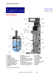
A= Display
B= Keypad
C= RS232 Port
D= Memory Card Slot
E= Peristaltic Pumps
F= Magnets in vessel
G= Pt-100 Electrode Cable
H= pH Electrode Cable
I= Oxygen Electrode Cable
J= Antifoam Probe Cable
K=Baffles (not shown, optional)
R
L= Air Inlet
M= Operational Amplifier
N= Rotameter
O= Water Pipe for Gas Cooler
P= Water Valve for Gas Cooler
Q= Base unit - Heater Block
R= Water Inlet
S= Spring to retain vessel
T= Vessel Support shelf
U= S. Steel Tray for Bottles
V= Magnetic Stirrer
W= Port Fittings
X= Top Plate Clamp
Y= Support for drive shaft
Z= Drive Shaft
1=Top Plate
2= Overflow Pipe to Drain
3= Vessel Glass
4= Impellors
5= Sparger
F:\QS\Verk\Handbuch\Ser-hb\SixSer-e.doc
Service Manual Version 1.0 for SIXFORS
®
Page 1
SIXFORS SERVICE MANUAL
SIXFORS SERVICE MANUAL Version 1.0
TABLE OF CONTENTS
Page
WHERE TO LOOK:
BASIC
INFORMATION
1
Dimensions, technical data and services requirements
4
2
Installation & basic operation
7
INSTALLING A NEW
SYSTEM
3
Cleaning
12
CLEANING A UNIT
4
Exchange of consumable parts
4.1
4.2
4.3
4.4
4.5
5
Basic Operation
Drive System
Temperature System
pH System
Dissolved oxygen system
Antifoam & Feed Pump
IRIS Software Connections to Sixfors
16
17
18
19
20
21
22
HOW TO EXCHANGE
KEY COMPONENTS
Repair items
6.1
6.2
6.3
6.4
6.5
6.6
6.7
6.8
6.9
6.10
6.11
6.12
7
WHAT COULD BE
WRONG?
Troubleshooting guides
5.1
5.2
5.3
5.4
5.5
5.6
5.7
6
Vessel seal
13
O rings on port fittings & clamping ports
13
Membranes/filters/reagent bottle fittings
14
Replacing drive bearings (& removal of drive shaft & impellors) 14
Battery on memory card
15
ROUTINE
EXCHANGE OF
CONSUMABLES
Testing of process parameters - setup, calibration, actuators
Removal of covers/basic sections of the Sixfors
Exchange of Pt-100
Removal and exchange of digital pcb
Exchange of heating element/over-temperature sensor
Exchange of drive motor
Exchange of rotameter inner cylinder
Exchange of operational amplifier module
Exchange of cooling valve (in base section)
Exchange of peristaltic pump components
Exchange of main pcb/eprom/micro-processor
Exchange of screen & keypad
23
24
25
25
25
25
26
26
27
27
29
30
Installation of Optional Accessories Post-delivery
7.1
Linking to IRIS software/troubleshooting/connection/setup
Service Manual Version 1.0 for SIXFORS
®
31
Page 2
HOW TO ADD
ADDITIONAL ITEMS
SIXFORS SERVICE MANUAL
8
Appendices
8.1
8.2
8.3
8.4
8.5
8.6
8.7
8.8
8.9
8.10
8.11
8.12
SPECIFIC
INFORMATION AS
INDIVIDUAL SHEETS
PID drawings (SixPOver.doc)
Electrical schematics (Sixelec.pdf / Driverbus.cdr)
Pump head/ flow rate details (Sxflowrate.doc)
Where to find the Serial No (SerialCont.doc)
Contact details for Infors (SerialCont.doc)
Sixfors Components – What’s Where? (SxWhtWhr.doc)
U-DDC Instrumentation (sixUDDC.doc)
Addendum to Sixfors U-DDC installation information (UDDCInstS.doc)
Addendum PID Control Overview (PIDover.doc)
Sixfors – Outline diagnostic table (SxFaults.doc)
Initial setup of electrodes (ElecPrep.doc)
Service Agreement – Checks for annual preventive maintenance (SixAnSer.doc)
Service Manual Version 1.0 for SIXFORS
®
Page 3
SIXFORS SERVICE MANUAL
1. Dimensions, Technical Data and Services Requirements.
Working volume
No. of vessels
No. parameters
:
:
:
Approx. 0.3 to 0.5L
Up to six, round or flat bottom
o
C, rpm, pH (measure & PID control)
pO2 (measure & PID control + options),
antifoam or substrate (cycle/dose control).
Optional mass flow control and gas mix.
No. reagent pumps:
3 per base unit
Temperature Control:
Heater block temperature control (incl. cooling)
with a single- walled vessel.
Temperature Range:
5 C under coolant temp. to 60 C
Heating
125W per station
Stirrer
Electronic, DC stepper motor with
PWM control
Bottom drive with magnetic coupling,
Stirrer bar or impellors & baffles (option)
Airflow
24-60NL/Hr
Speed range(s):
approx. 20-1200 rpm
Data connection
RS232 (Tx, Rx and ground only)
Profile storage
Memory card (type PCMCIA)
pH range:
2-12pH
pO2 range:
0-100%
Antifoam:
Total cycle time and dose time-30% max
Feed Pump:
Total cycle time and dose time-30% max
Optional conductivity probe
o
o
Dimensions (Length x Depth x Height)
Weight
Services
9000 x 400 x 710 mm
67Kg
Electricity
Water
Air
230V, 50Hz 10A ("noise-free")
> 1.5 bar
~1.5 bar*
Service Manual Version 1.0 for SIXFORS
®
Page 4
SIXFORS SERVICE MANUAL
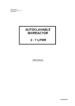
Overview of the SIXFORS Systems of Measurement & Control
TEMPERATURE
PID Loop1 Temperature
INPUT
Op Amp
OUTPUT
Heater Cooling
Valve
Temperature is controlled using an electrical heating block with in-built cooling coil.
The range of control is approximately 5ºC above the cooling temperature to 60ºC. A
signal from a Pt-100 temperature sensor in the culture is used for feedback control
by the micro-processor to activate either the heater or the cooling valve. The main
controller display shows actual value, setpoint PID control etc.
Pt-100
STIRRER SPEED
P ID Lo op 2 S pe e d
A n- IN
S pe ed
PCB
O UTP U T
M oto r
A setpoint is given to the control circuitry by the
microprocessor. The PID control values
are factory set for this parameter. The main display
shows the actual value for speed. The level of
dissolved oxygen can be cascaded to influence the
stirrer speed. Speed range is typically 20-1200 rpm
upper and lower limits depending on the EPROM installed
for a specific application. No service adjustments can be made.
Adjustments cannot be made using potentiometers and
dip switches on the speed controller pcb in the second
section of the base unit.
Ta ch om e ter
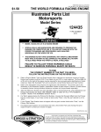
pH
PID Loop3 pH
INPUT
Op Amp
OUTPUT
Acid
Pump
Alkali
Pump
pH
The pH measurement and control system consists
of an electrode linked to a signal conditioning module
which sends the measured value to the microprocessor.
Calibration is digital and similar to the procedure for a
bench meter. Range is typically pH 2-12.
Integrated peristaltic pumps deliver a timed dose of
either acid or alkali reagent into the fermenter vessel.
The total “on” time of each pump is recorded and can
be used to measure how much reagent has been added.
Temperature compensation can be activated if required.
A gas valve for CO2 may replace the acid pump.
DISSOLVED OXYGEN
PID Loop4 pO2
INPUT OUTPUT1 OUTPUT2
Op Amp
Motor
Thermal
Mass Flow
Val ve
Measurement of dissolved oxygen is via an electrode
linked to an integrated operational amplifier within the
signal conditioning module. A polarising voltage is also
supplied by this unit. Calibration is similar to a bench
meter with zero and 100% values being set.
Control is by a PID loop acting on either the stirrer
speed or by influencing an optional thermal mass
flow control valve to adjust the air flow rate.
A gas-mixing unit can be used for special applications
such as animal cell culture. Range 0-100%
PO 2
Service Manual Version 1.0 for SIXFORS
®
Page 5
SIXFORS SERVICE MANUAL
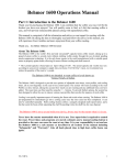
ANTIFOAM (optional)
PID Loop5 Foam
INPU T
O p Amp
O UT PU T
Antifoam
Pump
Control of foam is based on a conductivity
probe above the culture surface detecting
the build-up of foam by contact with the
probe tip. The rest of the probe is insulated
to prevent false signals.
After a user-selectable waiting time (delay)
the integral peristaltic pump delivers a dose
of antifoam reagent (shot).
The system then resets and will only add more
reagent if foam is still present.
This arrangement can double as a level control
system to remove culture.
Probe
GAS FLOW
Gas Flow Rate - Manual
Air OUT
Rotameter
Air IN
Unless specified otherwise, control of gas flow
into the fermenter is usually set manually. A
separate pump or laboratory air supply is
connected to the fermenter supply pipework
which has an integral pressure regulator valve.
The flow rate is adjusted using a rotameter
calibrated in litres per minute/hour.
The maximum air flow rate should be no more
than 1.5 vessel volumes per minute.
A mass flow valve and/or gas mixing system may also be used.
CHEMOSTAT OR CONTINUOUS OPERATION (optional)
M edium IN
INP UT
O UT PU T
ON
1 0 S e cs
O FF
5 0S e cs
F ee d Pu m p
Sh o t &
De la y
K e ypa d
S e tt in g s
or
A n alo gu e
O r A n alo gu e
M edium O U T
INP UT
O p Am p
O UT PU T
Ha rvest
Pu m p
Pro b e
This relies on a balance being set between
addition of fresh medium into the vessel and
removal of culture. The correct rate matches
the growth of the microbes so that a constant
concentration in the vessel is maintained.
If the growth of the organism is limited by
eg. a source of sugar in the medium then the
fermenter is being operated as a chemostat.
Medium is added to the culture by a
peristaltic pump which can be an integrated
digital unit relying on shot and delay times or
an external analogue pump with variable speed.
Harvest of culture can be achieved by using
a level control system (antifoam pump used
in reverse to withdraw culture), or a simple
side-arm acting as an overflow (option).
Even if the fermenter is operated as a
chemostat for a short time, large containers
are needed for both fresh medium and harvest.
Antifoam reagent can be added to the fresh medium
at a low concentration (eg. 1:20,000) if required)
Service Manual Version 1.0 for SIXFORS
®
Page 6
SIXFORS SERVICE MANUAL
2. Setup and Basic Operation
Transport
Packing and disposal
n view of the weight of the complete SIXFORS
and packing materials it should never be carried
by one person alone. For moving the packed
system over long distances, a low trolley or palette
raiser is recommended.
The SIXFORS is shipped in a wooden crate. All
packing materials are environmentally friendly and
can be re-cycled.
If the SIXFORS is to be transported by a fork lift
truck, it is vital it is secured in such a way that
there is no chance of it falling off or otherwise
being damaged!
Please make sure that no part of the SIXFORS
sustains damage during unpacking. Use the
delivery documentation to ensure that all parts are
present. If there is a discrepancy between the list
and the contentss and/or there are any signs of
transport damage, please contact Infors at once.
If this advice is not followed promptly, any resulting
costs will be the responsibility of the purchaser.
Unpacking and Checking.
All accessories and flexible connection pipes are
usually packed in a cardboard box placed on top of
the fermenter base unit. The vessel is also packed
in a separate cardboard box within the crate.
Location
Services
The SIXFORS fermenter is best mounted on a
laboratory bench of suitable working height.
Access to air, water and power services should be
nearby along with a suitable drain / sink.
A free space of 50cm should be left all around the
fermenter to make servicing both easier and
quicker.
The unit should be sited away from
potential sources of electrical noise.
The final connection of the fermenter to the services
will be made by INFORS if installation is requested
by the customer.
This is aided greatly when all services outlets
include the necessary pressure reduction system
already installed by the customer.
Services Connections
Power
Water Inlet
230V/10 A single-phase supply for standard
SIXFORS
Cold (& preferably soft, <50ppm suspended solids)
water supplied at a pressure of >= 1,5 bar enters
from the left side of the base unit of the fermenter.
Push-on connector pipes are supplied separately in
a bag. Push one of these into place and fit braided
tubing to the cold water tap. Use "jubilee clips" to
secure pipe to fitting at both ends.
The power supply should be clean and constant if not, it is recommend fitting of suitable filters and
or a UPS to the mains power supply.
In addition to the plug fuse, 2 fuses can be found
behind a cover above the location of the
connecting socket in the mains inlet and On/Off
switch.
Air
The air inlet can be found on the left side of the
fermenter. Use only clean, dry oil and dust free air
with a pressure of >= 2.0 bar.
A push-on Connector pipe is used with braided
tubing. Fit a "jubilee clip" at each end of the pipe to
secure it.
Inlet air is supplied through the rotameter (variable
area flow meter) to each vessel. Ensure this is
turned on using the black knob below the
rotameter scale.
Calibration graphs are provided in the operating
manual.
Water Drain
The drain outlet is on the left side of the fermenter. It
requires a clear fall to the drain / sink without sharp
bends or kinks.
Push fit onto metal barb connection.
Exit Air
The exit air leaves via the disposable filter attached
to the exit gas cooler (if fitted).
If oxygen supplementation is used, take care to pipe
the exit air away safely to avoid explosion risk.
Service Manual Version 1.0 for SIXFORS
®
Page 7
SIXFORS SERVICE MANUAL
Vessel connections:
Temperature control
Drive System
The vessel needs only to be placed into the heater
block by squeezing the smaller holder on the right
hand side away and letting the vessel slide in. The
block now acts like a heater jacket and allows heat
exchange with the vessel contents.
The bottom drive is automatically connected when
the vessel is placed in its holder. Ensure the drive
shaft (if fitted) is located correctly in the bottom
bearing support (the white teflon disk which is either
in the centre of the ring sparger or in a separate
triangular plate for round-bottom vessels).
Inlet of water into the heater block for cooling is
controlled by an automatic valve inside the bottom
section of the base unit.
A special version of the EPROM can be specified if
uncoupling is likely to occur during operation.
Connect the inlet and outlet pipes of the exit gas
cooler using the small rapid coupling connectors.
Use the manual valve behind each vessel to turn
the cooling water supply to the exit gas cooler ON.
Connection to a computer/Printer.
The vessel top plate is equipped with a Pt-100
temperature probe. This is in a 10mm clamped
port and a 2-pin Lemo connector. It is used for
connecting to orange cable from the operational
amplifier module. Push to fit when the red spots
on cable and connector are aligned.
The SIXFORS has an RS232 serial port on the left
side of the black support for the screen/keypad. If
specified, a cable should be provided which
connects to this port and a 9-pin serial port at the
rear of the computer. Installation and use of IRIS
software is the subject of another guide.
Gas supply
Printers must have a serial port or a parallel/serial
converter in order to link directly to the SIXFORS.
Fit a 0.22u filer to the top of the vessel sparger
using braided tubing (long enough to allow a
clamp to be placed between the filter and the
metal sparger pipe).
Connect the air line from the rotameter to the air
sparger in the vessel by braided tubing, pushing it
onto the air filter.
Additional cables and equipment.
Reagent bottles are normally provided with the
system. These are set up separately and for test
purposes can be filled with water. See diagram for
correct set-up.
If a gas mixing system is present, connect the gas
supply bottles to the appropriate inlets either to the
rear of the base unit or on the separate gas mixing
box.
Initial Setup Checklist
1.
2.
3.
4.
5.
6.
7.
8.
9.
10.
11.
Memory card in place
Water line connected
Drain line connected
Air line connected
Vessels connected to heating system
Rotameter outlet connected to sparger
Exit gas cooler inlet & drain connected
PT100 temperature sensor connected
Air supply turned on
Water supply turned on
Mains power on
This is purely for testing the basic functions of the
fermenter. Connecting of probes etc. is covered in
a separate section.
Service Manual Version 1.0 for SIXFORS
®
Page 8
SIXFORS SERVICE MANUAL
Bringing into use (from a service viewpoint)
1.
Check all O ring seals for wear and replace
as necessary. Smear with a little high temp.
grease.
2.
Undo the clamping ring using the screw at the
front of the vessel. The top plate can be lifted
clear of the vessel glass, which remains in
place.
3.
Check the large "O" ring seal (10962) in the
grooved flange of the vessel glass is lightly
greased, not damaged and not wrinkled when
in place.
4.
Charge vessel with water to approximately
the required working volume of the vessel.
5.
Replace the top plate and tighten retaining
clamp to finger tight. Take care not to
accidentally clamp the autoclaving cover for
the Pt-100 in the clamp.
6.
Equip any unused ports with a membrane,
collar and port closure if the port is to be used
for additions post-autoclaving. If not, a
blanking port closure is sufficient.
7.
Calibrate the pH electrode using the
appropriate menu option in U-DDC and
buffers of eg. pH 4 and 7. Follow the
instructions to set a low and high reading.
8.
The dissolved oxygen electrode low-value
calibration can be set using the zeroing gel
provided CARE- strongly alkaline solution.
9.
Fit the pH and dissolved oxygen electrodes in
the 13.5PG ports (they have a finer thread
than standard), using adaptors if the
electrodes are too long to fit without.
Cleaning or Assembly
Check the electrode condition, then
prepare the electrodes for first use
according to the instructions given
in the relevant appendix. i.e.
pH - remove white sealant over
diaphragm completely.
pO2- unscrew base section,
remove diaphragm cartridge and
half fill with electrolyte. Replace.
Calibrate
pH & pO2
Zero
The other vessel fittings can be added such as
sample pipe, exit gas cooler and acid/alkali inlets.
OPERATION
1.
Air flow should be set to no more than 1.5
vessel volumes per minute eg. for a 0.5L
working volume vessel the max. is
0.75NL/min.
2.
Pass the tubing from the reagent bottles
through the appropriate peristaltic pump,
using the small connector in these lines to
stop the tubing from being pulled through the
pump. Unclamp the connection between the
bottle and the vessel.
3.
Calibrate the 100% dissolved oxygen high
value by passing air through the vessel at
maximum flow rate when the stirrer speed is
also at the maximum to be used. At least 2-6
hours is needed before electrode is usable.
4.
Complete the set-up by setting appropriate
setpoint values. This should be sufficient for
an installation check without autoclaving.
Service Manual Version 1.0 for SIXFORS
Connect
tubing
Calibrate
pO2 100%
®
Page 9
SIXFORS SERVICE MANUAL
•
UDDC Instrumentation (basic points)
•
The UDDC2 instrumentation is based on a powerful
industrial process controller which uses a memory
card ( type PCMCIA) to store data about Set-points,
profiles etc.
•
The keypad is splashproof and has several
sections, each with keys which perform specific
tasks:
Numeric keys [1]..[9] plus [.] Data Entry
numbers 1..6 .
Select fermenter
[+/-]
"Toggles" options
[Enter]
Confirmation
[Esc]
Abort last action
[UP ARROW]
Moves upwards
[DOWN ARROW]
Moves downwards
[Menu]
Go to Main Menu
•
Fermenter data
Current option
Fermenter values
HELP information
A square flashing cursor [] appears in a number of
screens against something which can be changed.
STARTING OR STOPPING A FERMENTER
1.
2.
3.
4.
5.
6.
7.
1 Fermenter Menue
3 Printer/Comms
5 Password
2 Parameter Menue
4 Hardware Options
6 Copy Memory Card
The screen is a high-contrast LCD unit displaying
40 characters by 16 lines. Different areas of the
screen provide different sorts of information:
Top Line
Second line
Lines 4-13
Lines 15-16
•
Main Menue
To start a fermenter from the Main Menu select
Option 1, fermenter Menu.
The screen changes to allow you to select which
fermenter (1..6) to start using the numeric keypad.
The Fermenter Menu is then displayed. Select
Option1, Start/Stop.
In the start/Stop screen use the [DOWN ARROW]
key to move through the options, deciding which
parameters to keep On and which to switch Off
using the [+/-] key.
Finally, use the [+/-] key to switch Start Fermenter
to On and press either [Enter] or [Menu] to confirm.
[Menu] takes you back to Main Menu and
pressing[Esc] will let you see the Values screen.
To stop an active fermenter, select Option 1,
Start/Stop from the Fermenter Options menu and
use the [+/-] key to toggle Stop fermenter to On &
press Enter] or [Menu] to confirm the shutdown.
CHANGING A SETPOINT
Fermenter Menu
Fermenter: F 1
1 Start/ Stop
3 Fermenter
5 Edit Profile
7 Ferm. Overview
9 Alarms
2 Parameter Menu
4 Pump/ Flow Settings
6 Profile Control
8 Pump Timings
0 pO2 Control def.
Fermenter: >F1< Status OK
00d00:00
[Start/Stop]
_______________________________________________
Fermenter: F1
PH Control : Off
pO2 Control : Off
Temp Control : Off
RPM control : Off
Antifoam
: Off
START FERMENTER; Off
_____________________________________
Menu for Main Menu
+/- to change value; Enter / Esc to exit
There are two ways to change a setpoint:
1.
2.
3.
4.
5.
6.
From the Values Screen - simply press [Enter] after
first selecting the fermenter (1..6) and then the
required parameter with the cursor using the
UP/DOWN keys for navigation.
Alternatively, press [Menu] to show the Main Menu
and press [1] to select the Fermenter Menu.
Press [2] for the Parameter Menu. The Parameter
Selection sub-menu will allow you to choose the
parameter you want to change eg.[1] RPM.
A new setpoint is entered using the numeric keys
and confirmed with [Enter].
[DOWN ARROW] moves to the Alarm Lim. field
where a symmetrical alarm limit value can be
entered outside of which an alarm will be
generated.
Press [Enter] to confirm the value and [Enter]
again to return to the parameter menu.
Fermenter >F1<
STATUS OK
0d:14:13
[Setpoints]
>F1<
RPM
Temp
pH
pO2
AF
I
I
I
I
I
>F2<
....
37.0
7.0
80
Off
>F3<
>F4<
I
I
I
I
I
Menü for Main Menu; +/- for Values
Enter: edit setp
Service Manual Version 1.0 for SIXFORS
®
Page 10
|
|
|
|
|
>F5< >F6<
|
|
|
|
|
|
|
|
|
|
SIXFORS SERVICE MANUAL
CALIBRATION
1.
Calibration of parameters is possible for both active
and closed down fermenters. The RPM parameter
cannot be calibrated as this is factory set.
2.
3.
4.
5.
6.
7.
Press[Menu] to get to Main menu
[2] to select parameter menu
eg.[1] to select the fermenter (1..6)
eg.[2] to select the desired parameter
(1..5)
[2] to select the Calibrate screen
8.
Enter the High Ref. values using the numeric keys
eg. 60oC and press [Enter] to confirm.
Press [DOWN ARROW] to move on.
The High Read is a value generated by the A/D
converter in the instrumentation - press [Enter] to
allow the reading shown in the Act Read display to
replace the current value in the High Read position.
Use the [DOWN ARROW] key to pass over the
value.
Repeat the process for the Low Value and Low
Reading.
Press ENTER to confirm or Menu.
9.
10.
11.
12.
13.
PUMP/FLOW CONTROL
1.
2.
3.
4.
5.
6.
7.
8.
9.
This screen allows the built-in reagent and feed
pumps to be set to ON. OFF or AUTO control.
Acid, Base and Feed pumps can be ON. OFF or
AUTO eg. when the acid and base pumps are
under the control of the pH control system.
The feed pump can only be set to ON or OFF.
The cycle and set values are in seconds and allow
different flow rates to be achieved by varying the
time a pump is active over time. The maximum duty
cycle for any pump is 40% of the total cycle time
eg. cycle=60, set=24 secs.
This screen is reached via the Fermenter Options
Menu.
Use the [+/-] key to toggle On, Off or Auto options
[DOWN ARROW] moves on to the next position.
Enter the cycle time in seconds and use [Enter] to
confirm the new value. [DOWN ARROW] moves
you on. Repeat for the Set time.
The flow setting allows the thermal mass flow valve
(if fitted) to be controlled with a manual value for
gas flow rate in litres per minute. This valve is
usually under the automatic control of the pO2
control system.
A final [Enter] or [Menu] confirms the new values.
[Esc] aborts the process
[Parameter Menu]
Fermenter:F1:
1
3
5
Parameter: pH
Setpoint
PID Setup
Calibrate all
2
4
Calibrate
Controller View
Select option: Menu for Main Menu;
Enter or esc to Exit
Fermenter >F1<
[Calibrate]
OK
STATUS
Fermenter: F1
High Ref:
Low Ref:
Slope:
■ 7.000
■ 4.1
- 0.00379
Sensror Data
Act read: 0612
Parameter:
pH
High Reading
Low Reading
Offset
2048
1024
11.98
Act Value: 0.00
Ref Temp: 24.3
Slp mV/pH: 56.3
Fermenter >F1<
[Pump/Flow Settings]
00d00:00
STATUS OK
00d13:00
Fermenter F1
Acid Pump :Auto
Base Pump:Auto
AF Pump :Auto
Feed Pump:ON
Flow Out : Auto
Cycle: 60 Set: 0
Cycle:60 Set:24
Cycle:60 Set: 0
Cycle:60 Set::18
Value (l/min)0
Select Option: Menu for Main Menu
Enter or Esc to exit
DEF PO2
1.
2.
3.
4.
5.
This screen allows several options to be set for
control of dissolved oxygen. It is accessed from the
Fermenter Menu.
If Flow Control is set to On using the [+/-] key then
oxygen control is via the optional thermal mass flow
control valve.
If the RPM control is set to On, then speed is used
to control pO2 - either in place of the flow valve or
additional to it!
Max Influence sets a symmetrical limit in RPM in
which control of pO2 can take place eg set point of
1000RPM with max. influence of 200 would give
control of pO2 by stirrer speed from 1200 to 800
RPM only. This is the only standard option!
Gas Mix and hand Mix only apply to systems with a
special gas Mix unit.
Fermenter: >F1< Status OK
00d00:00
[pO2 Control Def. ]
_______________________________________________
Fermenter: F1
Flow Cont : On
RPM Cont: On
Gas Mix : Off
Hand Mix : 0
Max Infl: 100
_____________________________________
Menu for Main Menu
+/- to change value; Enter / Esc to exit
Service Manual Version 1.0 for SIXFORS
®
Page 11
SIXFORS SERVICE MANUAL
3. Cleaning
Before disconnecting the corrective reagent feed lines from the
peristaltic pumps they should be clamped off. They can then be
emptied manually after re-sterilization.
Mains switch
On the right hand side of the base unit
OFF.
On safety grounds, the fermenter must be switched off and left
for some minutes before removing the vessel(s) for cleaning of
the base unit (heating block can get very hot to the touch).
Cleaning the base unit and Master-Control
panel.
1.
Use a soft, damp (NOT WET) cloth and a
neutral detergent to wipe away any stains or
grime.
2.
Clean the unit down with electrical power off
and allow to dry completely before use.
3.
Any spillages of reagents (especially acid or
alkali) must be wiped up immediately - CARE
NEEDED.
Examination of the vessel during cleaning
During cleaning of the vessel, an examination for
any chips or cracks in the vessel glass can be made
and faulty vessel glasses MUST be replaced.
Any O ring seals which appear flattened or dry
should be replaced and the new seals lightly
greased with a mineral compound such as eg.
Edwards' high vacuum grease.
Membranes which have been pierced should be
replaced.
Cleaning of a recently-used system
Please note: sterilization of the vessel and
peripherals MUST be done by the user prior to
your starting work on the equipment!
1.
The pH and dissolved oxygen electrodes
should be removed and stored in suitable
reagents according to the manufacturer's
instructions which come with each electrode.
Copies are included in the appendices of this
operating manual.
2.
Periodic cleaning and regeneration of the
electrodes are also covered by these
instructions.
3.
The vessel should be rinsed several times in
distilled water to remove any loose culture
residues.
4.
Growth of culture on the vessel walls may
require disassembly and light brushing to
completely clean the glass.
Service Manual Version 1.0 for SIXFORS
®
Page 12
SIXFORS SERVICE MANUAL
4. Exchange of Consumable Parts
During a routine service inspection, a number of consumable parts may have to be exchanged.
4.1 Vessel seal
The vessel seal is critical for maintaining an
uncontaminated environment for the culture.
1.
Remove the clamping ring from the vessel to
release the top plate.
2.
Carefully lift the top plate upwards so the
pipes etc. clear the lip of the glass section
and place the top plate gently on its side
away from the glass section. The glass
section will continue to be supported by the
metal frame surrounding it.
3.
The vessel seal is a large "O" ring sitting in a
groove in the flange at the top of the glass
section. If it is flattened or shows signs of
fraying then it should be replaced with a new
one.
4.
The new seal is very lightly greased with
silicone grease and placed in the groove. It
must fit snugly without any wrinkles. If a good
fit cannot be achieved, discard the seal and
use a new one.
5.
Re-assemble the top plate onto the vessel
glass and replace the clamp using even
pressure the clamping screw (finger tight
only).
4.2 "O" rings on port fittings & Clamping Ports
The "O" rings seal the port closures against the
top plate so no microbes can get in or out. If their
effectiveness is compromised, the fermenter is
functionally useless.
The port closure "O" rings are located in grooves
in the closure and can be easily levered out for
exchange. Remember to lightly grease the new
"O" ring.
Port fittings which have pipes going through them
(e.g. harvest pipe, antifoam probe), use a
clamping arrangement to secure the pipe in
addition to the "O" ring which actually seals
against the top plate.
The antifoam electrode has an insulating sheath
that fits over the length of the probe, leaving only
the tip exposed.
Service Manual Version 1.0 for SIXFORS
®
Page 13
SIXFORS SERVICE MANUAL
4.3 Membranes, filters, Reagent Bottle Fittings
& Sampling Device.
Reagent Bottle Parts Disassembled
These additional items are usually replaced by the
user as necessary. However, as part of routine
maintenance, it makes sense to check any fittings
in these perpiheral items (eg. dip tubes) for
corrosion and to replace clearly worn or damaged
membranes and fittings.
Cap
Dip tube
Bottle
Needle
4.4 Replacing drive bearings & removal
of drive shaft/impelllors
1.
2.
3.
4.
5.
6.
7.
8.
Remove vessel top plate.
Undo nut holding the top of the drive shaft in
place
Draw drive shaft past the top bearing support
Press on teflon bearing support to pop it out
of its retaining metal frame
Replace with a new teflon bearing (18217)
Replace drive shaft and re-assemble
The bottom bearing support pops out of the
centre of the ring sparger or triangular frame
in the same way. This is more likely to wear
and needs regular exchange as a
consumable item. (22786)
The impellors are exchanged/moved by
releasing the small grub screws holding them
firmly onto the drive shaft using a small
hexagonal key.
Service Manual Version 1.0 for SIXFORS
®
Air filter
Page 14
Membrane
SIXFORS SERVICE MANUAL
4.5 Battery on Memory Card
The memory card (AFC003) stores information
about setpoints, calibration, PID setup, profiles
and other preferences. A "watch" batttery
preserves tha data on the card even when the
SIXFORS is switched off. After a period of 1-2
years the battery loses power and the user reports
a loss of settings every time the unit is switched
off.
A further reason for wishing to remove the battery
may be that a "PIN number" password has been
set and the user has forgotten it. Removing the
battery clears the memory.
The user will normally exchange the batttery
themselves but may well ask for it to be done as
part of preventive maintenance.
1.
Remove the card from the slot in the
SIXFORS main pcb housing (noting the
orientation of the card).
2.
A small screw is found on the back edge of
the card. Remove this with the special tool
provided with the card or using a
watchamaker's screwdriver.
3.
Put your fingernail or eg. a thin penknife blade
into the small crack above the area containing
the screw hole and pull backwards.
4.
A battery holder is revealed with the battery
sitting in position. Note the orientation of the
battery and exchange for a new one. TYPE:
xxxxxxx
5.
Ensure the write protect tab on the back edge
of the card is seet towards the middle of the
card in the "Write" position before replacing it
in the SIXFORS.
Memory Card
"Screwdriver" Screw Battery Write protect
Holder
tab
The card will be "initialised" by the SIXFORS on
first switching the fermenter on and all setpoint
values set to zero with defaults for all other data.
If the customer has downloaded the current
configuration to a PC, the data can be restored to
the card using Option 6 in the Main Menu "Copy
Memory Card".
Service Manual Version 1.0 for SIXFORS
®
Page 15
SIXFORS SERVICE MANUAL
5. Trouble-shooting the Sixfors
5.1 Basic Operation
Problem
Possible Causes
Power lead not plugged in or
Mains power not turned ON
Sixfors does not work at all
Fuses blown
Remedy
Plug in - switch mains ON
Check plug fuse (10A+)
Check fuse in base unit (10A)
(No green mains power light)
Break in power connections
Mains power, but no display
Check plug connections
Test mains cable continuity
Check connections at mains
socket in base unit
Check reset in plug socket
Unit switched ON but not
touched for longer than 30
minutes
Touch any key. LCD screen
should now light.
No 24V supply. Can the red
LED's indicating 24V supply be
seen in the LED display in the
base section of the Sixfors for
each unit? If NO
Check power supply to 24V feed
from transformer. Replace
transformer if necessary.
Replace back light
No Back light. Can figures be
seen dimly in the LCD display? If
YES
Check 24V feed to main pcb
No 24V supply to pcb.
Main pcb or back light faulty. If
24V supply to main pcb OK, can
peristaltic pumps be operated
manually? If YES
If NO
LCD Screen halts at P.O.S.T.
Screen
(Power On Self Test)
Screen shows random
characters and /or "odd"
behaviour of pumps etc.
System "hangs" or does not
respond to inputs
Keys fail to work
No Memory card. Do all tests
show pass and the display asks
for memory card to be inserted?
If YES
Processor Problem
Replace screen panel
Replace main pcb
Memory card should be inserted.
N.B. Never insert or remove a
memory card if the unit is
switched on
Switch On and OFF to clear
fault. If no change, remove &
replace processor or exchange it
for a new one.
Memory card problem
Re-initialise card/remove battery
briefly to clear mem.
Processor problem or fault with
keypad
Switch On and Off. If no change
replace keypad or processor (try
processor first)
For general, random faults with operation, pumps etc. check earthing & "digital" pcbs If setpoint,
calibration etc. data is not being retained, exchange memory card battery.
Service Manual Version 1.0 for SIXFORS
®
Page 16
SIXFORS SERVICE MANUAL
5.2 Speed Control System
Problem
Possible Causes
Remedy
Speed controller OFF. Is the
speed control switched ON at
"Start Fermenter" or "Fermenter
Options" screens?
Switch ON.
PO2 control switched on and set
to work with stirrer
Switch pO2 Control by Stirrer
OFF to test operation
Stirrer setpoint=0
Check Stirrer set point >0 and
deadband does not include zero
rpm.
Motor does not start
Drive shaft not moving.
Can the drive shaft be turned by
hand ? If NO (unlikely)
No power to motor.
Is power being supplied to motor
?
No power getting to motor from
digital pcb
Remove obstruction or replace
bearings on drive shaft -usually
bottom bearing
Replace digital pcb or motor
Check connections.
Speed control malfunction.
Does speed match displayed
value for speed? (visual
estimation) If NO
Check connections to digital
controller pcb
Is more than one motor
affected? If YES
Check connections to motor on
digital pcb for power supply etc.
Drive motor runs slowly or
erratically (pulses or "hunts")
If PO2 control by stirrer is
switched ON, turn it OFF
Motor bearings failure.
Replace motor
Drive uncouples at high speed
Culture viscosity is too high
Service Manual Version 1.0 for SIXFORS
Reduce speed
Fit special EPROM
®
Page 17
SIXFORS SERVICE MANUAL
5.3 Temperature System
Problem
No display or incorrect
display of temperature
Possible Causes
Remedy
Faulty Pt-100 sensor
Check connections
Test calibration with eg. ice and
hot water
Faulty amplifier module
Processor problem
Replace amplifier module
Check connections
Replace Pt-100 and re-test
Control not active
Switch OFF and ON again.
Replace processor
Ensure control is turned ON
Control output not given - Check
indicator LED's, is the heater
light ON? If NO
Check connections
Replace digital pcb
No temperature control
Processor Fault
Check "Fermenter Overview"
does this show heater/cooling
valve active?
If No
Check connections
Replace processor or main pcb
Does the vessel get hot?
If NO
No heating or inadequate
heating
Over-temp. cut out fault
Faulty heating element
Check connections
Replace cut out
Replace heater element
Faulty "digital" pcb
Check operation
Neg factor too high - control
biased towards cooling
Check connections
Replace heater
Check power output to heater
Replace pcb
Adjust
No Water or inadequate flow
No cooling or inadequate
cooling
Set a low setpoint eg 5oC,
Does the aluminium block and
vessel contents begin to cool? If
NO
Turn cooling water ON
Check connections
Check connections
Replace cooling valve
Faulty cooling valve
Incorrect Neg. Factor
Temperature drifts up or down
over time
PID settings incorrect
Service Manual Version 1.0 for SIXFORS
Adjust eg. if cooling water
temperature is too high.
Adjust (esp. P term) - default
values available
®
Page 18
SIXFORS SERVICE MANUAL
5.4 pH System
Problem
Possible Causes
Faulty pH electrode
Remedy
Check connections
Test calibration with pH 4 and
ph7 buffers
Check slope of electrode for
signs of ageing
Replace or regenerate electrode
Turn this to ON in normal use
No display or incorrect
display of pH
Temp compensation OFF
Faulty amplifier module
Processor problem
Control not active
Switch OFF and ON again.
Replace processor
Ensure control is turned ON
Pumps not set to Auto
Check and set to Auto if
necessary (pumps submenu)
No control in dead band
Ensure this is OFF or small
value
No reagents
Ensure bottles full, line open &
connected to vessel
Pumps not operating properly
Check operation manually
and prime pumps.
If pump heads do not rotate
Faulty pump motor
No pH Control
Wrong tubing type
Faulty Solenoid
Is only one pump effected?
If YES
Control output not given - Adjust
set points. Check indicator
LED's, do the acid and base
pumps lights ON? If NO
Processor Fault
Check "Fermenter Overview"
does this show acid/alkali pumps
active? If NO
pH drifts up or down over time
or acid & alkali added almost
continuously in turn
Check connections
Replace sensor or use simulator
to test
Replace amplifier module
Check connections
Check drive belt
Replace pump motor
Check tubing type (not too hard)
and spring tension
Check connections to solenoid
Replace solenoid
Check connections
Replace digital pcb in base
section (also for pump malfunctions)
Check connections
Replace processor or pcb
PID settings incorrect
Adjust (esp. P term) - default
values available
Incorrect strength of reagents
Check reagents ~0.1-2.0M
Service Manual Version 1.0 for SIXFORS
®
Page 19
SIXFORS SERVICE MANUAL
5.5 Dissolved oxygen system
Problem
Possible Causes
Faulty pO2 electrode
No display or incorrect
display of dissolved oxygen
Remedy
Check connections
Test calibration with zeroing gel
and max. speed + air flow
Use simulator if available
Check slope of electrode for
signs of ageing. IS IT DRY?
Replace membrane or whole
electrode
Faulty amplifier module
Check connections
Replace sensor or use simulator
to test
Replace amplifier module
Processor problem
Switch OFF and ON again.
Replace processor
Control not active
Switch control ON
Actuator not switched to ON
In "Po2 Def" screen, select
stirrer, flow and/or gas mix as
appropriate.
Other settings must be made for
flow and gas mix to work.
(only control by stirrer is
available as standard, factory
default is for flow control to be
set ON, so this must be
changed)
No gas flow into vessel
Fault with Actuator
a) Drive Motor
No dissolved oxygen control
Check for bubbles in culture
Check service supply
Check as in 5.2
Replace if necessary
b) Mass flow control valve
Check connections
Replace if necessary
c) Gas Mix unit
Check connections
Check services supply of gas
Check solenoid valve operation
(listen for activation, does valve
get warm over time, test for flow
with air)
Replace valve if necessary
Dissolved oxygen drifts up or
down over time or stirrer
"hunts"
PID settings incorrect
Service Manual Version 1.0 for SIXFORS
Adjust (esp. P term) - default
values available
Full 3-term control is often
needed for good pO2 control
®
Page 20
SIXFORS SERVICE MANUAL
5.6 Antifoam/Feed Pump
Problem
Foam not sensed
Foam always/frequently
detected
Possible Causes
Remedy
Faulty Antifoam electrode
Check lead & amplifier by
shorting cables together, does
display show "AF ON" and/or
pump operates
If YES
If NO
Check connections
Replace antifoam probe
Replace amplifier module
Processor fault
Check connections
Replace
Antifoam probe sheathing
damaged (unlikely)
Replace probe
Pump switched to ON
Switch pump to Auto
Processor fault
Control not active
Check connections
Replace
Ensure control is turned ON
Pumps not set to Auto
Check and set to Auto if
necessary (pumps submenu)
No reagent (or inadequate)
Ensure bottles full, right reagent
& connected. Line open to
vessel.
Pump not operating properly
If pump heads do not rotate
Faulty pump motor
Check operation manually
and prime pump.
Check connections
Check drive belt
Replace pump motor
Antifoam control does not
work
Wrong tubing type
Faulty Solenoid
Is only one pump effected?
If YES
Control output not given - short
out probe.. Check indicator
LED's, does the antifoam pump
lights ON?
If NO
Processor Fault
Check "Fermenter Overview"
does this show antifoam pump
active? If NO
Feed Pump does not work
(see above for range of possible
pump faults)
Pump not switched to ON
(same pump as antifoam)
No set value given
Service Manual Version 1.0 for SIXFORS
Check tubing type (not too hard)
and spring tension
Check connections to solenoid
Replace solenoid
Check connections
Replace digital pcb in the lower
front of the base (also for pump
malfunctions)
Check connections
Replace processor or pcb
Switch pump ON
Give cycle & set times (secs)
®
Page 21
SIXFORS SERVICE MANUAL
5.7 IRIS Software Connections to Sixfors (assumes prior correct installation by Infors)
Problem
No Data-logging or control
Possible Causes
Remedy
Cable not connected
Connect firmly at both ends
Cable connected to wrong COM
port
Check which COM port a
fermenter is assigned to and
swop if needed.
Cable connected to wrong
fermenter
Swop cable if necessary.
Cable not earthed at one end
Ensure earth strap connected at
the computer end to a case
screw
Fermenter not switched to
remote operation
Select this option at the
Fermenter instrumentation.
COM port settings incorrect
Fermenter mis-assigned
Check in Peripherals dialogue
box (Extras, menu, devices submenu).
Check in Fermenter Properties
dialogue box.
Device model incorrect eg. set
for ISF not Labfors
Error opening com port
Message-box appears
Wrong protocol for comms.
Eg. baud rate or parity mis-set.
Click on Settings button in
Peripherals dialogue box and
check settings re. fermenter
manual.
Conflict with other devices on
COM port eg. a mouse
Ensure the fermenter COM port
is not shared - check Control
Panel settings in Windows
COM port settings incorrect
Check in Peripherals dialogue
box (Extras, menu, devices submenu)
COM port not existing on this
computer
Try different com-port
Conflict with other devices on
COM port eg. a mouse
Ensure the fermenter COM port
is not shared - check Control
Panel settings in Windows
Parameter not set for this
Click remote operation ON in the
Edit Measured Parameter
dialogue.
Fermenter settings are not
correct
Set accept remote on the
fermenter control panel.
Backup value may be ON look in Text view table
Click backup value OFF in the
Edit Measured Parameters
dialogue
Logging but no Control
No change in logged value
Service Manual Version 1.0 for SIXFORS
®
Page 22
SIXFORS SERVICE MANUAL
6. Repair Items
6.1 Testing of Process Parameters - setup, calibration
actuators etc.
The Sixfors can be thought of as a single container for
measurement and control using at least 5 different operational
sub-systems i.e. temperature, speed, pH, dissolved oxygen
and foam/feed. This applies for up to six separate vessels: see
Section 2 for explanations of standard functions.
Part of fault diagnosis and repair requires that you have a
knowledge of how each process parameter is controlled and
setup for normal operation.
This requires familiarisation with the section of the operating
manual dealing with the U-DDC instrumentation. A short guide
is included in Chapter 2 for testing on installation but more
detailed information is required for fault diagnosis.
If the Sixfors does not function at all on switching ON, check
the cable fuse, laboratory earth trips and main fuse on the
machine by the power indicator light. A fuse is also present on
the motor controller pcb (printed circuit board).
Testing each parameter should follow a common pattern:
1.
2.
3.
4.
5.
6.
7.
8.
9.
10.
11.
12.
13.
Ensure relevant probe is in place - look for signs of
damage or eg. no electrolyte or physical dents,
Ensure correct services are switched ON eg. water
Ensure the parameter has a realistic setpoint for the test
eg. to check the cooling valve, the temperature setpoint
may be set to 5oC.
Check that control in Dead Band (BD) is switched to ON
&/or the actual value for Deadband is near zero eg. <0.5
Check calibration of parameter before starting fermenter.
Check PID values for irregularities eg. large I value or no
P value.
Start fermenter and ensure the parameter is turned ON
If pumps or valves are involved, make sure these are
switched to Auto or have realistic manual set valves.
Monitor the action of controllers via the "Fermenter
Overview" screen and LED indicators in the third section:
Use your senses for additional verification of actuators
working eg. if the heater works, the vessel will get hot or
you may be able to hear solenoid valves "click" on or off.
Some parameters take a long time to get to fullyoperational condition eg. dissolved oxygen electrode
needs at least 2 hours with power supplied. Don't take the
first value as correct, especially soon after autoclaving.
Look at measured values and the raw A/D converter
readings on the calibration page - do they roughly match
eg. pH7= approx. 512 - an A/D reading of 100 or 1000
would suggest a fault (see addendum for more info.)
Unexpected values or odd behaviour from measurement
probes can sometimes indicate an earth problem which
may not show up on a conventional electrical test (eg. the
dissolved oxygen electrode is very sensitive to a poor
earth connection, leading to the value drifting high).
Default values for calibration and settings are provided within
the EPROM for re-initialised cards and new installations - see
separate addendum UDDC installation information sheet.
The next stage in fault investigation usually requires you gain
access to the relevant actuator for more direct tests:
CHECK COMPONENTS BY SWAPPING WITH THOSE IN
ANOTHER UNIT OF THE SAME TYPE IF POSSIBLE.
pH and Dissolved Oxygen Simulator
Calibration is best achieved using a certified
simulator for pH and dissolved oxygen as
this tests both the cable and amplifier (a
suitable unit is made by the Valley
Instrument Co Inc. of Exton, PA. USA) If
calibration is successful using the simulator,
incorrect readings can then almost certainly
be attributed to a faulty probe or earthing
problem.
A simulator can be used for temperature also
but it is often cheaper and easier to carry a
spare Pt-100 sensor known to be calibrated
properly (ice water and boiling water provide
2 certain reference points at normal altitudes
and atmospheric pressures).
If you do not have access to a simulator,
useful tests can still be performed on site.
LED
INDICATOR
RELATES TO THE
ACTION OF:
Motor
Acid Pump
Base Pump
Feed Pump
Reserved
Reserved
Cooling Valve
Heater
Overtemp always ON
24V Power always ON
Indicator LEDS in the Base
section of the Sixfors
Service Manual Version 1.0 for SIXFORS
®
Page 23
SIXFORS SERVICE MANUAL
6.2 Removal of Covers -Main Sections of the Sixfors
The base unit of all Sixfors contains the following
Bottom Section rear:
1. 3 panels held by 4 screws each (flat head)
2. For left & right panels lift reagent bottle platform out of the
way by lifting back and pulling backwards at an angle of
approx. 30o to release front lugs
3. Remove panel(s)
4. The middle panel is "popped out" by moving it slightly left
and pulling out and rightwards to get it free of the
instrument support struts. This panel is replaced first
You have access to:
Left Side:
•
Water inlet & pressure regulation valve
•
Air inlet & pressure regulation valve
•
Water outlet
Middle:
•
Solenoid valves x6 for cooling water
•
Large white capacitor for 24V supply
Right Side:
•
Transformer
•
Rotameter pipework
•
Mains inlet
•
Power connector block
•
Ribbon cable (base unit to instrumentation)
•
Across all areas:
•
Solenoids for peristaltic pump operation
•
Roller for pumps
•
Rear of heating/cooling blocks for each unit
•
Pcb cooling fans for each position
Bottom Section Left rear
Bottom Section - lower front:
Bottom Section
Right Rear
Undo the 10 screws along the length of the front bottom panel
and lift forward and downwards gently to gain access to:
1.
2.
3.
Stepper motors mounted individually
Magnets on top of stirrer motor
Digital pcb with diagnostic lights
Bottom Section - upper front:
Access to:
1. Heater blocks
2. Sprung retainers for vessel
3. Rotameters for air flow control
4. Manual control valves for exit gas cooler water inlet
5. Three peristaltic pumps per station
6. .Peristaltic pump heads
7. Rollers x2
8. Solenoid valves to pull pump heads onto roller
Bottom Section front
6.3 Main pcb Housing, Screen and Keypad
From the front side you can gain access to:
1.
2.
3.
4.
5.
Memory card slot on left
RS232 serial port for printer/computer connection on back
Small instrument fan
Screen & keypad
Backlight & buzzer pcb
Top Section
The mains socket (main fuse), the hour counter, ID plate are
at the right rear of the base unit.
Service Manual Version 1.0 for SIXFORS
®
Page 24
SIXFORS SERVICE MANUAL
6.3 Exchange of Pt-100
1.
2.
3.
4.
Locate Pt-100 on vessel top plate (10mm port)
Remove retaining screw (flat head)
Withdraw vertically
If necessary, replace with one of same size
6.4 Exchange of the digital pcb in the lower, front base
1.
2.
3.
4.
Undo single screw (flat head) at front of pcb on heat sink
Pull pcb forwards part way
Remove 4 pin connector to the motor and the 2 pin
connector to the small fan behind the pcb
Pull pcb and integral heat sink out (17940)
Note the onboard fuse
6.5 Exchange of Heating element & over-temperature
sensor (supplied together)
The indication of a need for exchange will be:
1.
2.
3.
Digital pcb removal
No heating (maybe a dead short on the element also check using a multi-meter).
The controller output indicates heating is called for
There is power entering and leaving the connections on
the "digital pcb" to the heater
To exchange the heating element & overtemp. sensor:
1)
2)
3)
4)
5)
6)
7)
8)
Remove rear covers
Disconnect heater/over-temperature sensor cable (white
connector)
Undo the 2 x large screws (hexagon key needed) holding
the support block to the base unit
Push the block forwards slightly from the back and push
the heater/overtemp connector through.
Remove the green water tubing by pulling it backwards off
the connector firmly.
The block is now free and can be upended so the heater
and overtemp. sensor can be unscrewed and removed
and replaced as necessary (Part no's 17648/22662).
On re-assembly, use a little heat conducting paste in the
groove where the overtemp sensor is located.
When replacing cooling water pipes, check carefully for
any leakage before replacing the covers.
6.6 Replacement of the drive motor (17946)
1)
2)
3)
4)
5)
Open front lower cover
Remove digital pcb
Loosen small screws (hexagon key needed) to left and
right of the motor. Do not remove totally
Pull motor (on supporting bracket) forwards
Replacement is the reverse of this procedure
Heating element &
Ovetemp sensor
Other electrical components can be exchanged:
1.
2.
3.
4.
5.
6.
The 2-way magnetic cooling valves (group of six in
middle) for cooling water distribution to support blocks
Mains power inlet socket and filter
Fuse 10A
Mains ON light and green cover
Operational hour counter
Transformer for 24V supply
Service Manual Version 1.0 for SIXFORS
Removal of drive motor
®
Page 25
SIXFORS SERVICE MANUAL
6.7 Exchanging the rotameter inner cylinder
Calibration tables are included for each rotameter type in the
Sixfors operating manual., The scale on the Vogtlin rotameters
is calibrated in Newton litres/hr as standard and the type is
given by the code after the manufacturer's name eg. V100-80.
To exchange the inner cylinder gauge glass (which is the
actual variable area tube):
1.
2.
3.
4.
Undo the four screws (flat head) holding the transparent
front cover
Undo the large screw at the top of the rotameter block
using a hexagon key
The glass tube is now loose and can be replaced
Watch out that the front cover is the right way around
when replacing as the screw holes are countersunk.
Rotameter glass loosened
6.8 Exchange of the operational amplifier pcb (17649)
The purpose of the pcb is to digitise the analogue signals from
the electrodes. Exchange may be necessary if eg. a sensor
value cannot be calibrated properly even with a simulator.
Check the connections from the electrode cap and cable
wiring before reaching this conclusion!
To exchange the pcb:
1)
2)
3)
4)
5)
Undo single screw (flat head) beneath individual op map
module.
Pull forwards and down gently to partly withdraw module
Whilst supporting the module remove the ribbon cable at
the rear (red wire to left hand end) to release the module
Undo the 2 screws (flat, cheese head) on top of the
module casing. Pull back and then lift to expose the op
amp pcb and cable connector
When replacing the cover, note the two lugs at the rear of
the supporting part of the module which fit into slots in the
back of the cover.
To adjust antifoam sensitivity:
1.
2.
3.
4.
5.
6.
7.
Remove the Op amp board
Remove the top cover
Remove the ribbon cable to free the cover then replace
At the front of the module, where the cables are
connected, is a blue potentiometer marked 1-9
When there is no foam, the diode above should be lit
To reduce sensitivity, turn the potentiometer away from
the 9 until the light goes out
For the foam sensor in the vessel, ensure the black wire
is connected to the vessel top plate and the red wire is
connected to the probe itself.
Measurement module with operational
amplifiers pcb
Service Manual Version 1.0 for SIXFORS
®
Page 26
SIXFORS SERVICE MANUAL
6.9 Exchange of an individual cooling valve (17801)
1.
2.
3.
4.
Remove the rear panels
Undo the two screws (flat head) holding the valve array to
the right angled support bracket
Undo the electrical connector to the valves
Move valve for better access to the screws at the rear and
remove the 4 small screws holding the valve body to the
manifold
Replace and reassemble
6.10 Exchange of peristaltic pump components.
The motor and drive belt for the peristaltic pumps can be
accessed from the top rear of the base section. The single
stepper motor drives two rollers which operates any (or all) of
the 18 peristaltic pumps on demand. This is normally switched
on permanently. Above this are housed the peristaltic pumps,
the solenoid magnets which pull the pump heads onto the
roller.
Access to the pumps & rollers:
1.
2.
3.
Undo all pump clamping bars and lift out of the way
Undo a single screw at the back of the top section of the
base unit and the 4 screws in front (all flat head)
Lever the top panel gently out of the way - lift towards the
front then slide along to the left when free of the pump
heads
Changing a solenoid (17955):
1.
2.
3.
4.
5.
6.
Remove the rear panels
Undo the two screws (flat head) at the top of each
solenoid
Lift the solenoid forward to clear the claw of the lifting bar
for the pump head
Pull down to free the solenoid
Cut or de-solder the wires to the solenoid
The block of three pumps for each vessel position can be
disconnected using the white connector block below each
pump grouping
Changing the pump drive belt (17814):
1)
2)
3)
Loosen the two large screws holding the motor using a
hexagon key
Lift the motor up slightly and support it
The drive belt is now loose enough to remove from the
upper pulley
Removing the motor for the peristaltic pumps (17946):
1)
2)
3)
4)
5)
6)
Take out the two screws holding the motor
Remove the drive belt
Unclip the connector for the motor wiring
Cut the earth wire to the motor
The motor is now free for removal
Check the tension of the drive belt on replacing
There is no need for disassembly of the rollers other than
in exceptional circumstances. Special instructions are in
an appendix to this manual and an outline is given below.
The rubber used for providing friction is now located on the
pump heads and can be simply pushed off the individual roller
and exchanged as necessary. This requires NO disassembly
of the pump head system.
Service Manual Version 1.0 for SIXFORS
Pump motor without drive belt
®
Page 27
SIXFORS SERVICE MANUAL
Exchange of the roller bars.
1.
2.
3.
4.
5.
Remove pump cover at the front
Remove rear panels
Loosen the two large screws holding the motor with a
hexagon key (do not remove) and slide the drive belt over
the top pulley to release it
Remove the screws holding the top of the supports for the
rollers in the left, middle and right positions
Remove the roller bars and replace as necessary.
Dis-assembly of the pump head section.
1.
2.
3.
4.
5.
6.
7.
8.
9.
Remove the front and rear panels as above
Pull out the plug connecting the motor to the power supply
Unplug the relevant group of three pumps (one white
connector for all three pumps)
Loosen the screws holding the motor with a hexagon key
so the drive belt can be slipped over the top pulley
Remove the 4 large screws (2 left, 2 right) with a hexagon
key to allow the whole pump support frame to be lifted
away. Place on the bench for further dismantling.
Remove the screws in the support frame (2 in each
frame) for holding the individual group of three pumps.
Only one side need be removed to allow the pump heads
to slide out individually.
Remove the relevant pump head and replace as
necessary.
Reverse the procedure for re-assembly.
Service Manual Version 1.0 for SIXFORS
®
Page 28
SIXFORS SERVICE MANUAL
6.11 Removal of Top Cover & Main pcb Modification/
Replacement of Master Units
1.
2.
3.
4.
5.
Remove memory card
Undo 3 screws (flat head) at top and three at front of the
instrument panel to release the top cover
Lift cover up and back gently to reveal the OP amp
modules (the top cover can be carefully rested on the
back of the instrument housing)
Remove all six Op amp modules
The main pcb is now exposed for simple work such as
exchange of processor or EPROM
Replacement of EPROM (22025 Sixfors A21)
1.
2.
3.
4.
5.
The EPROM gives the Sixfors its "identity". It made need
upgrading to eg. add an analogue box or other additional
facilities.
The EPROM is located to the left of the large, square
microprocessor chip located in the top third of the pcb.
Removal can be achieved using a chip extractor or by
gentle leverage with a penknife blade or fine screwdriver CARE.
Before placing the new EPROM in the empty socket
check the pins are all properly aligned and, if not, gently
press the side on the chip onto a hard surface to cause all
the pins on that side to move inwards fractionally.
Locate the EPROM correctly by lining up the notch cut out
of one end of the EPROM with a corresponding notch on
the socket. Press firmly into place ensuring no pins are
bent under during this process.
Replacement of the Microprocessor.
1.
2.
3.
Location of EPROM &
Processor
This is not normally necessary unless a fault condition
exists. The microprocessor is easily located as it is a
large, square, socketed chip in the top third of the pcb.
Removal must be made using the correct extraction tool
(available from main electronics suppliers) which has two
"claws" that locate into slots in the socket.
Note the position of two small circles on the chip
(diagonally opposite) relative to these long slots in the
socket so the new microprocessor can be correctly
oriented.
Removal of Processor
Service Manual Version 1.0 for SIXFORS
®
Page 29
SIXFORS SERVICE MANUAL
Replacing the main pcb (21696)
1.
2.
3.
4.
5.
6.
7.
8.
9.
Note positions of all ribbon cables and connectors
Earth yourself for work on the main pcb
Take out the 2 ribbon cables and the 3 pin cable joining
the screen/keypad unit to the main pcb
Undo the 2 earth leads on the front cover
Remove the screen and keypad section complete with the
front cover. This can now be worked on separately.
There should now be free access to the main pcb
Remove ribbon cables for connection to the base, 24V
power, and the connection to the small instrument fan at
the rear of the instrument housing.
Undo the 3 screws (flat head) at the rear of the main pcb
Lift upwards and then back to remove the pcb
Replacing main pcb
6.12 Replacing Screen and/or Keypad (21557)
1.
2.
3.
4.
5.
6.
7.
Place glass screen face down on a cloth for protection.
Undo the 6 small nuts holding the LCD screen pcb on
right.
Retain all spacers and ceramic washers.
Undo the earth lead at the bottom of the housing.
Disconnect small connector at the bottom of the keypad
pcb which links two white leads from the LCD pcb to the
small, perpendicular pcb across the keypad area.
Lift LCD panel and remove/replace as necessary.
Remove the small perpendicular pcb by undoing two
small retaining nuts. The keypad area can now be
removed if required.
Screen & Keypad Interior
Re-assembly
1.
2.
3.
4.
5.
Fit the earth lead to the lower left hand side of the housing
Put the 4 small spacers into place and replace the screen
pcb.
Re-fit the perpendicular pcb and re-connect the white
wires from the screen.
Fit and tighten the retaining nuts to hold the screen pcb
into place.
Reconnect the earth leads.
LCD Screen & Light/Buzzer pcb (18335)
removed
Service Manual Version 1.0 for SIXFORS
®
Page 30
SIXFORS SERVICE MANUAL
7.1 Linking to IRIS Software - Troubleshooting,
Connection & Set-up
IRIS NT software provides data-logging, graphical display,
archiving and supervisory set point control (SSPC) for Infors
fermenters.
The software must be installed on a PC running Microsoft
Windows 9x or NT4/2000. The link to the Sixfors is made via
an RS232 serial cable which connects directly to a port on the
main pcb.
Control of the type of output and communications protocol is
handled by special settings available in the "Printer/Comms"
menu option of the U-DDC instrumentation. Use of the Sixfors
with a printer can also be controlled from here.
Details of installation of the IRIS software and operation with
the Sixfors is given in the operating manual for IRIS NT. This
section deals with the very basic physical set-up and simple
troubleshooting for an installed system you may find already
connected.
Serial cable connections
Troubleshooting for an installed system:
See chart in Section 5.8
Connection (to a PC or a printer):
1
RS 232
On the side of the unit, a male, 9-pin connector is provided.
Description
Pin Configuration
Pin 2 receive data (RD)
Pin 3 send data (TD)
Pin 5 Signal ground
2
6
3
7
3
8
Computer Side
25 pins
Computer Side
9 pins
SDDC pins
7
3
2
5
2
3
5
3
2
Ground
Tx/Rx
Rx/Tx
No other connections are used by the SIXFORS. For a
functional data connection, the cable must match this
schematic. A cable (9 Pin female - 9 Pin female) is available
from INFORS.
Should your serial connection be to a 25-pin socket, a
standard 9-25 pin adaptor can be used to allow a direct
connection.
It is possible to make your cable connections according to the
table and schematic shown. Note! With 9-pin to 9-pin
connecting plugs, the data lines 2 and 3 must be crossed.
If a printer is to be connected, this must be via a SERIAL
connection or a serial to parallel converter must be used.
It needs no additional settings to be made. Also, when a
terminal programme is used, it is not necessary to issue a
command for data to be transmitted.
Setup:
1.
2.
3.
4.
5
9
Connect one end of the serial cable to the Sixfors
Connect the other end to the 9-pin serial port of the PC
(Com1 or Com 2)
Connect the earth lead at one end to a good earth point
eg. a casing screw.
Refer to IRIS manual for operation from this point.
Service Manual Version 1.0 for SIXFORS
®
Page 31