1
REPAIR INSTRUCTION
HR7740/80
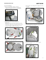
To remove the PCB´s:
1. Remove the 2 screws to loosen the Main PCB.
To remove the upper part of the coupling:
1. Remove the retaining ring with a screwdriver.
To remove the PCB Frame:
1. Release the 3 snaphooks, which hold the PCB on the
frame.
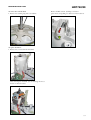
To remove the lower part of the coupling:
1. Remove the retaining ring with a screwdriver.
Soldering of Motor wires on PCB:
- Here you can see the colours of the Motor wires and their
soldering points on the PCB.
In this situation you can exchange for example the
coupling fork.
If you want to exchange the toothed wheel, you have to
remove the coupling fork and also the small axle from the
„click & go“ system (green arrow).
Solder point 2 - white wire
Solder point 3 - yellow wire
Solder point 4 - brown wire
Solder point 5 - black wire
Solder point 1 - red wire
8-9