1
MP
Series
Updated 6/12
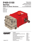
Triplex Ceramic Plunger Pump
Operating Instructions/
Repair and Service Manual
Pump Models:
MP4120
MP4124
MP4135
MP4130
MP4130HK
Contents:
Installation Instructions:
Pump Specifications:
Exploded View:
Parts List / Repair Kits:
Trouble Shooting:
Repair Instructions:
Torque Specifications:
Dimensions:
Warranty Information:
page 2
page 3
page 4
page 5
page 6
page 7-11
page 11
page 11
back page
INSTALLATION INSTRUCTIONS
Installation of the Giant Industries, Inc.,
pump is not a complicated procedure, but
there are some basic steps common to all
pumps. The following information is to be
considered as a general outline for installation. If you have unique requirements,
please contact Giant Industries, Inc. or
your local distributor for assistance.
3. The discharge plumbing from the pump
should be properly sized to the flow rate to prevent line pressure loss to the work area. It is
essential to provide a safety bypass valve between the pump and the work area to protect
the pump from pressure spikes in the event of
a blockage or the use of a shut-off gun.
4. Use of a dampener is necessary to minimize pulsation at drive elements, plumbing,
connections, and other system areas. The
use of a dampener with Giant Industries, Inc.
pumps is optional, although recommended by
Giant Industries, Inc. to further reduce system
pulsation. Dampeners can also reduce the
severity of pressure spikes that occur in systems using a shut-off gun. A dampener must
be positioned downstream from the unloader.
1. The pump should be installed flat on a
base to a maximum of a 15 degree angle of
inclination to ensure optimum lubrication.
2. The inlet to the pump should be sized for
the flow rate of the pump with no unnecessary restrictions that can cause cavitation.
Teflon tape should be used to seal all joints.
If pumps are to be operated at temperatures
in excess of 160o F, it is important to insure a
positive head to the pump to prevent cavitation. See chart below.
5. Crankshaft rotation on Giant Industries, Inc.
pumps should be made in the direction designated by the arrows on the pump crankcase.
Reverse rotation may be safely achieved by
following a few guidelines available upon
request from Giant Industries, Inc. Required
horsepower for system operation can be obtained from the charts on page 3.
6. Before beginning operation of your pumping
system, remember: Check that the crankcase
and seal areas have been properly lubricated
per recommended schedules. Do not run the
pump dry for extended periods of time. Cavitation will result in severe damage. Always remember to check that all plumbing valves are
open and that pumped media can flow freely to
the inlet of the pump.
Finally, remember that high pressure operation in a pump system has many advantages. But, if it is
used carelessly and without regard to its potential hazard, it can cause serious injury.
IMPORTANT OPERATING CONDITIONS
Failure to comply with any of these conditions invalidates the warranty.
1. Prior to initial operation, add oil to the crankcase so that oil level is between the two lines on
the oil dipstick. DO NOT OVERFILL.
2. Pump operation must not exceed rated pressure, volume, or RPM. A pressure relief device
must be installed in the discharge of the system.
Use SAE 85W - 140 Industrial Gear Oil
Giant’s p/n 01154
3. Acids, alkalines, or abrasive fluids cannot be
pumped unless approval in writing is obtained
before operation from Giant Industries, Inc.
Crankcase oil should be changed after the
first 50 hours of operation, then at regular intervals of 500 hours or less depending on operating
conditions.
4. Run the pump dry approximately 10 seconds
to drain the water before exposure to freezing
temperatures.
2
MP SERIES -- PUMP SPECIFICATIONS
U.S. Measurements
Model
MP4120
MP4124
MP4135
MP4130
MP4130HK
Max.
Max.
Power
Speed
Req'd.
Max. Flow Pressure
GPM
PSI
RPM
HP
8.9
3625
1450
23.1
12.8
2610
1450
24
13.5
1885
1100
18.2
15.4
1600*
1100
17.6
15.4
1600
1100
17.6
* Intermittent rating of 2000 PSI
Metric Measurements
Model
MP4120
MP4124
MP4135
MP4130
MP4130HK
Max.
Max.
Power
Speed
Req'd.
Max. Flow Pressure
L/min
Bar
RPM
kW
33.8
250
1450
17.2
48.6
180
1450
17.9
51.2
130
1100
13.6
58.2
110*
1100
13.1
58.2
110
1100
13.1
* Intermittent rating of 140 Bar
Max.
Plunger
Temperature Diameter
F
in
160
0.787
160
0.945
160
1.1
160
1.2
195
1.2
NPSH
Required
Ft-Head
24.6
27.9
29.5
29.5
N/A
Max.
Plunger
Temperature Diameter
C
mm
70
20
70
24
70
28
70
30
90
30
NPSH
Required
mWs
7.5
8.5
9
9
N/A
Consult the factory for special requirements that must be met if the
pump is to operate beyond one or more of the limits specified above.
Horsepower Ratings:
We recommend a 1.15 service factor be specified when selecting an electric motor as the power source.
To compute electric motor horsepower required, use the following formula: HP = (GPM X PSI) / 1450.
The formula to determine the horsepower required for a gas engine is: HP = (GPM X PSI) / 1150.
The formula to determine the horsepower required for a diesel engine is: HP = (GPM X PSI) / 1250.
For the Application of a Hydraulic Motor:
To Determine the Torque of a Hydraulic Motor -- (GPM x PSI x 36.77) / RPM = Torque (in-lbs)
Calculating RPM / GPM of Pump:
A pump must be connected to an electric motor or gas or diesel engine with the correct ratio of pulleys
and belts to attain the required speed and GPM. The use of a Variable Frequency Drive (VFD) may also
be used to control the RPM of a properly sized electric motor when variable flows are required.
(Max. Pump RPM / Rated Pump GPM) x Required Pump GPM = Required Pump RPM
To calculate a pulley diameter one (1) pulley diameter and the required pump RPM must be known:
(Pump RPM x Pump Pulley Diameter) / Motor RPM = Motor Pulley Diameter
(Motor RPM x Motor Pulley Diameter) / Pump RPM = Pump Pulley Diameter
Common Specifications:
Inlet Pressure.........................145 PSI (10 Bar)
Crankshaft Diameter...............1.10” (28mm)
Crankcase Oil Capacity...........32 fl. oz. (1.0 L)
Inlet Ports..............................(2) 1” NPT
Discharge Ports......................(2) 3/4” NPT
Stroke....................................1.02” (26mm)
Weight....................................66 lbs (30kg)
Shaft Rotation............Top of Pulley Toward
Fluid End
3
Materials Used for MP Pumps:
Manifold......... Aluminum Bronze
Plungers........ Solid Ceramic Oxide
Valves............ High Grade Stainless Steel
Seals............. Nitrile with Fabric Reinforcing
Gear End....... Spheroidal Cast Iron
Exploded View - MP Series
4
MP Series Parts List and repair kits
ITEM PART #
DESCRIPTION
QTY.
1
06100
Crankcase
1
2
13000
Oil Filler Cap Assembly
1
4
07243
Cover, Crankcase
1
5
07244
O-Ring, Crankcase Cover
1
8
01008
Oil Dip Stick
1
9
01009
O-Ring, Dip Stick
1
10 01010
Screw, Crankcase Cover
4
11
01011-0400 Spring Washer
4
12 07109
Oil Drain Plug
1
13 07182
Gasket, Oil Drain Plug
1
14 07245
Bearing Cover
2
15 07247
Seal, Crankshaft
2
16 07627
O-Ring, Bearing Cover
2
17 07114
Hex Screw, Bearing Cover
9
20 07248
Roller Bearing, Tapered
2
20A 07249
Shim
2
20B 06962
Fitting Disc
2
21 07250
Shaft Protector
1
22 07251
Crankshaft
1
23 07252
Key
1
24 07253
Connecting Rod
3
25 07596
Crosshead Complete
3
28 07255
Crosshead Pin
3
29A 07256
Centering Sleeve
3
29B 07262
Ceramic Plunger, 20mm (MP4120W) 3
29B 13046
Ceramic Plunger, 24mm (MP4124W) 3
29B 07261
Ceramic Plunger, 30mm (MP4130W, 3
MP4130HK)
29B 13005
Ceramic Plunger, 28mm (MP4135W) 3
29C 13007
Bolt, Sold only w/#07258
3
29D 07258
Seal Washer
3
30 06136
Flinger
3
31 07260
Crankcase Oil Seal
3
35A 07263
Rear Support Ring (MP4120W)
3
35A 06079
Rear Support Ring (MP4124W)
3
35B 06064
Rear V-Sleeve (MP4120W)
3
35B 06080
Rear V-Sleeve (MP4124W)
3
35C 07265
Rear Pressure Ring (MP4120W)
3
35C 06081
Rear Pressure Ring (MP4124W)
3
35D 07266
Rear O-Ring (MP4120W)
3
36 07267
Snap Ring
3
39 07268
Pressure Ring (MP4120W)
3
39 06082
Pressure Ring (MP4124W)
3
39 07271
Pressure Ring (MP4130W)
6
39 13013
Pressure Ring (MP4135W)
6
40 07322
V-Sleeve (MP4120W)
3
Plunger Packing Kits
DESCRIPTION
QTY.
V-Sleeve (MP4124W)
3
V-Sleeve (MP4130W)
6
V-Sleeve (MP4135W)
6
V-Sleeve (MP4130HK)
6
V-Sleeve (MP4130HK)
3
Support Ring (MP4120W)
3
Support Ring (MP4124W)
3
Support Ring (MP4130W)
6
Support Ring (MP4135W)
6
Spacer (MP4120W, MP4124W)
3
Intermediate Ring (MP4130W, MP4135W)
3
Tension Spring (MP4120W/MP4124W) 3
Tension Spring (MP4130W, MP4135W) 3
Tension Plug (MP4120W/MP4124W)
3
Tension Plug (MP4130W, MP4135W)
3
O-Ring (MP4120W/MP4124W)
3
O-Ring, Tension Plug (MP4130W, MP4135W)
3
Manifold Head (MP4120W/MP4124W)
1
Manifold Head (MP4130W, MP4135W) 1
Valve Seat
6
O-Ring, Valve Seat
6
Valve Plate 6
Discharge Valve Spring
3
Inlet Valve Spring
3
Spring Retainer, Discharge
3
Plug, S.S. (MP4120W, MP4124W)
3
Plug, Brass (MP4130W, MP4135W)
3
O-Ring, Plug
3
Stud, Manifold
6
Shim, Stud
2
Nut, Manifold Stud
6
Spring Washer
6
Spacer
3
Valve Housing (MP4120W/MP4124W)
3
Valve Housing (MP4130W)
3
Spacer Ring (MP4120W)
3
O-Ring (MP4120W/MP4124W)
3
O-Ring (MP4130W)
3
O-ring (MP4120W)
3
Spring Retainer, Inlet
3
Disc for Crankshaft
1
Inlet Valve Assembly Kit
MP4120W
Item Part #
40
07322
35B 06064
# 09044
Description
V-Sleeve
Rear V-Sleeve
Qty
3
3
MP4124W
Item Part #
40
06083
35B 06080
# 09300
Description
V-Sleeve
Rear V-Sleeve
Qty
3
3
MP4130W # 09042
Item Part # Description
40
07272 V-Sleeve
Qty
6
MP4135W
# 09665
Item Part # Description
40
05687 V-Sleeve
Qty
6
MP4130HK Item Part #
40
06137
40A 07272
ITEM PART#
40
06083
40
07272
40
05687
40
06137
40A 07272
41
07270
41
06084
41
07273
41
06652
41A 07329
41A 07274
42
07275
42
07353
42A 06102
42A 06103
42B 07332
42B 07354
43
06104
43
06105
44
07280
44A 07281
45
07282
46
07283
46A 06959
47
07284
48
06108
48
07356
48A 07332
49
06109
49A 07319
50
07158
50A 07159
51
06110
52
06111
52
06112
52A 07329
53
12057
53
07332
53A 12027
54
06115
57
13020
# 09664
Description
Qty
V-Sleeve, High Temp 6
V-Sleeve
3
Item
42B
42B
44
44A
45
46A
53
53A
54
Part #
07354
07332
07280
07281
07282
06959
12057
12027
06115
# 09062
Description
Qty
O-Ring Tension Plug 3
O-Ring Tension Plug 3
Valve Seat
3
O-Ring, Valve-Seat
3
Valve Plate
3
Valve Spring
3
O-Ring
3
O-Ring 3
Spring Retainer
3
Discharge Valve Assembly Kit # 09043
Item
42B
44
44A
45
46
47
5
Part #
07332
07280
07281
07282
07283
07284
Description
Qty
O-Ring, Tension Plug 3
Valve Seat
3
O-Ring
3
Valve Plate
3
Valve Spring
3
Spring Retainer
3
PUMP SYSTEM MALFUNCTION
MALFUNCTION
The Pressure and/or
the Delivery Drops
Water in crankcase
Noisy Operation
Rough/Pulsating
Operation with
Pressure Drop
Pressure Drop at Gun
Excessive Leakage
CAUSE
Worn packing seals
Broken valve spring
Belt slippage
Worn or Damaged nozzle
Fouled discharge valve
Fouled inlet strainer
Worn or Damaged hose
Worn or Plugged relief valve on
pump
Cavitation
Unloader
REMEDY
Replace packing seals
Replace spring
Tighten or Replace belt
Replace nozzle
Clean valve assembly
Clean strainer
Repair/Replace hose
Clean, Reset, and Replace worn
parts
Check suction lines on inlet of
pump for restrictions
Check for proper operation
High humidity
Worn seals
Reduce oil change interval
Replace seals
Worn bearings
Replace bearings, Refill crankcase oil with recommended lubricant
Check inlet lines for restrictions
and/or proper sizing
Cavitation
Replace packing
Check system for stoppage, air
leaks, correctly sized inlet plumbing
to pump
Recharge/Replace accumulator
Check for proper operation
Check inlet lines for restrictions and/or proper size
Worn packing
Inlet restriction
Accumulator pressure
Unloader
Cavitation
Restricted discharge plumbing
Worn plungers
Worn packing/seals
Excessive vacuum
Cracked plungers
Inlet pressure too high
High Crankcase Tem- Wrong Grade of oil
perature
Improper amount of oil in crankcase
6
Re-size discharge plumbing to flow rate of pump
Replace plungers
Adjust or Replace packing seals
Reduce suction vacuum
Replace plungers
Reduce inlet pressure
Giant oil is recommended
Adjust oil level to proper amount
REPAIR INSTRUCTION - MP SERIES
Disassembly sequence of the GIANT MP Series Pumps
1. With a 27mm wrench, re-
move the three discharge
plugs (#48) and three inlet
plugs (#42A) from the
manifold (#43).
47
46
45
2. Inspect the plug o-rings
(#48A and #42B) and
replace as necessary.
44A
3. From the discharge port remove
the spring retainer (#47)
spring (#46) and the valve plate
(#45). Using the valve puller
(Available from Snap-On Tools)
remove the valve seat (#44)
44
4. Inspect all parts, especially the seating surface
of the valve plate (#45), and replace as necessary.
5. Remove the six manifold stud nuts
(#50) with a 19mm wrench. Remove the spring washers (#50A).
Tap the back of the manifold with a
rubber mallet to dislodge and slide
it off the studs (#49). The spacer
(#51) can now be removed by prying gently outward with a screwdriver through the front of the inlet
port.
6. To remove the inlet valve
assembly, insert a 13mm
socket with extension
51
44
44A
45
46A
52
through the rear of the
inlet manifold (#43) port
and tap it firmly with a
7. Pull the inlet valve assembly apart for inspection. Any resishammer. This will force
tance may be overcome by placing the valve housing (#52) in
the tension spring (#46A),
a brass jawed vise and carefully tapping the back of the valve
valve housing (#52) and
plate (#45) with a screwdriver. Inspect the valve seats (#44),
the remainder of the inlet
spring (#46A), o-ring (#44A) and o-ring (#53A for MP4120W/
valve assembly out through
MP4124W) for wear and replace them as necessary.
the front of the inlet port.
7
REPAIR INSTRUCTION - MP SERIES
36
8. From the front of the manifold
(#43), remove the packing assembly (#41A, 41, 40, and 39).
Use a small slide hammer puller
if necessary, or insert a wooden
dowel through the back of the
manifold and tap the assembly
out from the back to the front.
10. Note: The following procedure is only necessary
if a stud bolt (#49) has
been damaged and must
be replaced. To remove
the manifold studs (#49),
place a stud nut (#50),
lock washer (#50A), and
second nut on each stud.
Tighten the nuts against
each other. Hold the front
nut with one wrench, and
remove the stud bolt by
turning the rear nut counterclockwise with another
wrench. To reassemble,
turn the front stud bolt nut
clockwise.
39
40
41
9. Turn the manifold (#43) over and remove the rear v-sleeve
snap ring (#36). For MP4120W/MP4124W, remove the
rear o-ring (#35D). Remove the rear pressure ring (#35CMP4120W/MP4124W & #39-MP4130W/MP4135W), rear
v-sleeve (#35B-MP4120W/MP4124W & #40-MP4130W/
MP4135W) and rear support ring (#35A-MP4120W/
MP4124W & #41-MP4130W/MP4135W) These parts
should slide out with little resistance. If necessary, a
screwdriver may be used to pry outward. Replace all rubber parts and inspect the metal parts for wear.
29C
29D
29B
11. Inspect ceramic plunger pipe (29B). Clean any dirt or
grime. If the surface of the pipe is rough, scored or pitted,
replace plunger pipe. To remove the ceramic plunger
pipe, turn the plunger bolt (#29C) counterclockwise with
a 13mm socket. Use a steady torque to prevent ceramic
plunger pipe damage. Loosen and remove the plunger
bolt assembly (#29C and #29D) and replace the seal
washer (#29D).
31
12. Inspect the crankcase oil
seals (#31) for evidence of
leaking. If there is oil on
the crankcase (#1) at the
sight of the oil seals, they
must be replaced. The oil
seals are replaced after
removing the crosshead/
plunger assembly (#25) as
described on page 9.
13.Clean the bolt threads
(#29C), apply locktite,
and remount.
8
14. Torque the ceramic plunger
bolt assembly to 300 inch-
pounds (34 Nm). If originally
removed, reinstall the stud bolts (#49).
REPAIR INSTRUCTIONS - MP SERIES
15. Replace the rear support ring (#35A for MP4120W/MP4124W and
#41 for MP4130W/MP4135W). Replace the rear v-sleeve (#35B for
MP4120W/MP4124W and #40 for MP4130W/MP4135W) and rear
pressure ring (#35C for MP4120W/MP4124W and #39 for MP4130W/
MP4135W) making sure that the grooved side is facing the discharge
end of the manifold (#43). For MP4120W/MP4124W, replace the rear
o-ring (#35D) into the back of the manifold (#43). Replace the snap
ring (#36).
39
40
(40A in MP4135W)
41
16. Reinstall the pressure ring (#39), v-sleeve (#40 /
#40A fpr MP4135W), support ring (#41 / #40 for
MP4135W) and intermediate ring (#41A) into each
plunger bore. Re-install the tension spring (#42).
For MP4120W/MP4124W only replace the spacer
ring (#52A).
41A
(40 in MP4135W)
17. Reassemble the inlet valve assembly in the reverse order of step #6. Make certain all the components
are press fit together and that the spring retainer (#54) is slightly counter sunk in the valve housing (#52).
Grease the o-ring (#53) and replace it on to the valve housing. Reinstall the entire inlet valve assembly
into the manifold (#43). Replace the tension plugs (#42A) and tighten.
18. Reassemble the discharge valve assembly by placing the valve plate (#45),
spring (#46), and spring retainer (#47) on top of the valve seat (#44). Press
fit together. Place the entire discharge assembly into discharge port making
certain the assembly is properly seated. Replace discharge plug (#48) and
tighten securely.
19. Again lubricate the plungers (29B) and slide the manifold (#43) gently and
evenly over the plungers. Press the manifold firmly into place against the
crankcase (#1). Replace the spring washer (#50A) and tighten the manifold
stud nuts (#50) to 700 inch-pounds (79 Nm).
9
REPAIR INSTRUCTIONS - MP SERIES
Gear End Disassembly
20.Remove the manifold and plunger assemblies as described earlier. Make sure the oil is drained
from the pump before removing the crankcase cover (#4). Remove all screws (#10). Inspect the
crankcase cover o-ring (#5) for damage and replace it as necessary.
21.Remove the connecting rod screws and washers with a 6mm allen wrench. Remove the back
halves of each connecting rod (#24) . Push the connecting rods down as far as possible into the
crankcase (#1) housing. Note that the connecting rod halves are numbered (or colored) and that
the numbers (or colors) must be matched for reassembly.
22.Remove the crankshaft bearing cover screws (#17) with a 13mm wrench. Remove the key (#23) from
the crankshaft (#22).
23.Remove the bearing cover (#14) and any shims (#20A) if any. Remember to replace shims on the
same side of the crankcase (#1) during the reassembly.
24.Steady the pump rear assembly and, using a rubber mallet, tap the crankshaft (#22) from one side.
The far side bearing race will be removed and the near side race will remain in the crankcase. The
roller bearings (#20) will remain on the crankshaft. When both ends are free, the crankshaft can be
removed by hand.
25.To remove the remaining bearing race, place a dowel against the inside edge of the race and tap it
out with a rubber mallet. This is done only if the race wear surface has been damaged.
26.Inspect the bearing race removed with the crankshaft (#22) and replace if wear surface is damaged.
27.Note: The following procedure is only necessary if the inspection shows evidence of heavy
wear. Inspect the crankshaft (#22) and bearings (#20) for wear. To remove the roller bearings from
the crankshaft, use a three inch push puller with a pulley attachment. To remount the bearings, tap
the bearings down the well-lubricated crankshaft with the Giant Bearing Tool. Be sure that the bearing
is firmly seated.
28.Remove the connecting rod (#24) with the attached crosshead/plunger assembly (#25) from the
crankcase (#1) by pulling it straight out. The oil seals (#31) may now be removed by tapping them
out through the front of the crankcase. Be careful not to damage the snap ring.
29.Inspect the surfaces of the crosshead/plunger assembly (#25) and connecting rods (#24) for heavy
scoring or galling due to poor lubrication. Check for play at the joint between connecting rod crosshead/plunger assembly.
30.To remove the crosshead pin (#28) from the crosshead/plunger assembly (#25), the assembly should
be positioned in such a manner to prevent damage to the crosshead when driving the pin out. The
crosshead pin can be driven out by tapping on the tapered side of the pin.
Reassembly Sequence
Note: Always take time to lubricate all metal and nonmetal parts with a light film of oil before reassembly. This step will help ensure a proper fit, at the same time it will protect the pump non-metal parts
(elastomers) from cutting and scoring.
31.Take the crosshead/plunger rod assembly and insert the connecting rod (#24) into the crosshead/
plunger assembly (#25). Drive the tapered end of the crosshead pin (#28) into the beveled side of
the crosshead and through the connecting rod completing the assembly.
Note: The crosshead pin should not extend beyond either side of the crosshead in order to prevent damage to the crosshead bore of the crankcase.
32.Inspect the crankcase crosshead guides for any possible damage.
33.Replace the connecting rod (#24), crosshead/plunger rod assembly (#25) into the crankcase (#1).
34.If removed previously, replace the far side bearing race into the crankcase. Tap with a rubber mallet
until the edges are flush with the crankcase surface.
35.Remove the old crankshaft seal (#15) from the bearing cover (#14). Lubricate the edges of the new
seal and install using the standard Giant Bearing Tool. Remove the bearing tool and tap around the
perimeter of the seal with a rubber mallet to firmly seat the seal. Position the far bearing cover on the
crankcase (#1) and insert the cover bolts (#17). Tighten the cover evenly to the crankcase, setting the
bearing into position. Torque the cover bolts to 125 inch-pounds (14 Nm).
10
REPAIR INSTRUCTIONS - MP SERIES
Reassembly Sequence
36.Insert the crankshaft (#22) with the mounted bearings (#20) through the near side of the crankcase
(#1). Make certain that the numbers (or colors) or the crankshaft correspond to the numbers (or colors)
on the connecting rods (#24). Reinstall the near side bearing race by inserting it into the crankcase.
Supporting the crankshaft with one hand, tap the race with a rubber mallet until the edge is flush with
the crankcase.
37.Replace any shims (#20A, 20B) and position the bearing cover (#14) as before. Tighten the bearing
cover bolts (#17) evenly to position the bearing race. Torque the bolts to 125 inch-pounds. Once the
crankshaft reassembly is complete, oil the crankshaft races freely before replacing the connecting rod
(#24) end caps.
38.Reassemble the connecting rods (#24), matching the numbered (or colored) halves. Torque the connecting rod bolts (#24A) to 250 inch-pounds (28 Nm).
39.To replace the oil seal (#31) apply Locktite to the outside edges of the seal and install from the front
of the crankcase (#1). The side of the seal with the spring must face the oil. Make sure that the face
of the seal is flush with the crankcase.
40.Clean the back edge of the crankcase and replace the crankcase cover (#4). be careful not to pinch
the crankcase cover o-ring (#5).
41.Fill the crankcase with 32 fluid ounces of Giant oil or the equivalent SAE 85W-140 Industrial Gear oil
and check the oil level with the dip stick (#8). The proper level is center of the two lines. Reinstall the
Giant MP Series pump into your system.
MP SERIES TORQUE SPECIFICATIONS
Position
17
24
29C
50
Item#
07114
07253
13007
07158
Description
Torque Amount - in.-lbs. (Nm)
Hex Screw, Bearing Cover
Hex Screw, Connecting Rod
Bolt, Plunger
Nut, Manifold Stud
125 (14)
250 (28)
300 (34)
700 (79)
MP SERIES DIMENSIONS - Inches (mm)
NOTE: Contact Giant Industries for
Service School Information.
Phone: (419)-531-4600
11
giant industries Limited WaRranty
Giant Industries, Inc. pumps and accessories are warranted by the manufacturer to be free from
defects in workmanship and material as follows:
1.
For portable pressure washers and self-service car wash applications, the discharge manifolds are guaranteed for the life of the pump. Our other pump parts,
used in portable pressure washers and in car wash applications, are warranted
for five years from the date of shipment for all pumps used in NON-SALINE, clean
water applications.
2. 3. 4. One (1) year from the date of shipment for all other Giant industrial and consumer pumps.
Six (6) months from the date of shipment for all rebuilt pumps.
Ninety (90) days from the date of shipment for all Giant accessories.
This warranty is limited to repair or replacement of pumps and accessories of which the manufacturer’s evaluation shows were defective at the time of shipment by the manufacturer. The following items are NOT covered or will void the warranty:
1. Defects caused by negligence or fault of the buyer or third party.
2. Normal wear and tear to standard wear parts.
3. Use of repair parts other than those manufactured or authorized by Giant.
4. Improper use of the product as a component part.
5. Changes or modifications made by the customer or third party.
6. The operation of pumps and or accessories exceeding the specifications set forth in the Operations Manuals provided by Giant Industries, Inc.
Liability under this warranty is on all non-wear parts and limited to the replacement or repair of
those products returned freight prepaid to Giant Industries which are deemed to be defective
due to workmanship or failure of material. A Returned Goods Authorization (R.G.A.) number and
completed warranty evaluation form is required prior to the return to Giant Industries of all products under warranty consideration. Call (419)-531-4600 or fax (419)-531-6836 to obtain an R.G.A.
number.
Repair or replacement of defective products as provided is the sole and exclusive remedy provided hereunder and the MANUFACTURER SHALL NOT BE LIABLE FOR FURTHER LOSS,
DAMAGES, OR EXPENSES, INCLUDING INCIDENTAL AND CONSEQUENTIAL DAMAGES
DIRECTLY OR INDIRECTLY ARISING FROM THE SALE OR USE OF THIS PRODUCT.
The limited warranty set forth herein is in lieu of all other warranties or
representation, express or implied, including without limitation any warranties or merchantability or fitness for a particular purpose and all
such warranties are hereby disclaimed and excluded by the manufacturer.
Giant Industries, Inc., 900 N. Westwood Ave., Toledo, Ohio 43607
PHONE (419) 531-4600, FAX (419) 531-6836, www.giantpumps.com
© Copyright 2012 Giant Industries, Inc.
06/12 MP Series.indd