1
Rough Terrain Crane Specifications
|
RT600 Series
Cranes |
STANDARD BOOM EQUIPMENT
BOOM
BOOM HEAD
36-111' (10.67-33.53 m), four section full power boom. Telescoping
is mechanically synchronized with single lever control. The synchronization system consists of a single telescope cylinder and high
strength leaf chains to extend and retract the third section and the
tip section. The boom is a high-strength four plate design, welded
inside and out with anti-friction slide pads. Boom side plates are
made with stamped impressions to reduce weight and increase
strength. A single boom hoist cylinder provides for boom elevation of
-4 to 76 degrees. Maximum tip height 115' (35.05 m).
Welded to fourth section of boom. Five or six nylon load sheaves and
two idler sheaves mounted on heavy duty, anti friction bearings.
Quick reeving boom head. Provisions made for side-stow jib mounting.
OPTIONAL BOOM EQUIPMENT
JIBS
HOOK BLOCK
32' (9.68 m) side stow swing-on one-piece lattice type jib. Single
nylon sheave mounted on anti-friction bearing. Jib is offsettable at
0˚, 15˚ or 30. Maximum tip height is 146' (44.50 m).
Five metallic sheaves on anti-friction bearings with hook and hook
latch. Quick reeving design does not require removal of wedge and
socket form rope.
33-57' (10.15-17.30 m) side stow swing-on lattice type jib. Single
nylon sheave mounted on anti-friction bearing. Jib is extendible to
57' (17.30 m) by means of a 25' (7.62 m) manual pull-out tip section, roller supported for ease of extension. Jib is offsettable at 0º,
15º, 30º. Maximum tip height is 170' (51.82 m).
HOOK AND BALL
AUXILIARY BOOM HEAD
Removable auxiliary boom head has single nylon sheave mounted on
anti-friction bearing. Removable pin-type rope guard for quick reeving. Installs on main boom peak only. Removal is not required for jib
use.
12 ton (10.9 mt) top swivel ball with hook and hook latch.
ROUGH TERRAIN CRANE
RT600 SERIES
STANDARD UPPERSTRUCTURE EQUIPMENT
UPPERSTRUCTURE FRAME
All welded one-piece structure fabricated with high tensile strength
alloy steel. Counterweight is bolted to frame.
TURNTABLE CONNECTION
CONTROLS
Swing bearing is a single row, ball type with internal teeth. The
swing bearing is bolted to the revolving upperstructure and to the
carrier frame.
SWING
A hydraulic motor drives a double planetary reduction gear for precise and smooth swing function. Swing speed (no load) is 1.9 rpm.
SWING BRAKE
Heavy duty multiple disc swing brake is mechanically actuated from
operator’s cab by foot pedal. Brake may be locked on or used as a
momentary brake. A 360º house mechanical house lock is standard.
RATED CAPACITY INDICATOR
Rated Capacity Indicator with visual and audible warning system and
automatic function disconnects. Second generation pictographic display includes: boom radius, boom angle, boom length, allowable
load, actual load, and percentage of allowable load registered by bar
graph. Operator settable alarms provided for swing angle, boom
length, boom angle, tip height, and work area exclusion zone. Antitwo block system includes audio/visual warning and automatic function disconnects.
OPERATORS CAB
Environmental cab with all steel construction, optimum visibility, tinted safety glass throughout. and rubber floor matting is mounted on
vibration absorbing pads. The cab has a sliding door on the left side.
Framed sliding window on the right side, hinged tinted all glass skylight and removable front windshield to provide optimum visibility of
the load open or closed. Acoustical foam padding insulates against
sound and weather. The deluxe six-way adjustable seat is equipped
with a mechanical suspension and includes head and arm rests.
Armrest mounted dual axis controls for winch(s), swing, and boom
elevation. Winch rotation indication incorporated into control handles. Armrest swings up to improve access and egress. Vernier
adjustable hand throttle included. Steering column mounted turn signal, wiper, and shift controls. Switches include ignition, engine stop,
lights, horn, roof window wiper, defroster, steering mode, parking
brake, outriggers, 360˚ house lock, etc. Horn and winch speed shift
switches are mounted in the levers. Foot control pedals include
swing brake, boom telescope, service brake, and accelerator.
INSTRUMENTATION AND ACCESSORIES
In-cab gauges include air pressure, bubble level, engine oil pressure,
fuel, engine temperature, voltmeter, transmission temperature, and
transmission oil pressure. Indicators include low air, high water temperature, low oil pressure, high transmission temperature, and low
coolant level audio/visual warning, hoist drum rotation indicator(s),
and Rated Capacity Indicator. Accessories include fire extinguisher;
light package including headlights, tail light, brake lights, directional
signals, four-way hazard flashers, dome light, and back-up lights
with audible back-up alarm; windshield washer/wiper; skylight
wiper; R.H. and L.H. rear view mirrors; dash lights; and seat belt.
Circuit breakers protect electrical circuits.
HYDRAULIC CONTROL VALVES
Valves are mounted on the rear of the upperstructure and are easily
accessible. Valves have electric/hydraulic operators and include one
pressure compensated two spool valve for main and auxiliary winch,
and one single spool valve for swing. Quick disconnects are provided for ease of installation of pressure check gauges.
OPTIONAL EQUIPMENT
Auxiliary Winch, Single axis armrest mounted controllers CLP
Heater/Defroster, Hydraulically powered Air conditioner with or without hydraulic header, Diesel Heater/ Defroster, Work Lights, Rotating
Beacon.
STANDARD CARRIER EQUIPMENT
CARRIER CHASSIS
Chassis is Terex designed with four-wheel drive and four-wheel steer
(4x4x4). Has box-type construction with reinforcing cross members, a precision machined turn table mounting plate and integrally welded outrigger
boxes. Decking has anti-skid surfaces, including between the frame rails
lockable front tool storage compartment, and access steps and handles on
the left and right sides and on all four corners.
AXLES AND SUSPENSION
Rear axle is a planetary drive/steer type with 10.5' (.26 m) of total oscillation.
Automatic oscillation lockouts that engage when the superstructure is swung
10˚in either direction. Front axle is a planetary drive/steer type, rigid mounted
to the frame for increased stability.
STEERING
Hydraulic four-wheel power steering for two-wheel, four-wheel coordinated,
or four-wheel crab steer is easily controlled by steering wheel. A rear axle
centering light is provided.
Two-wheel:
Four-wheel:
Turning Radius:
(to CL of outside tire)
41' 7" (12.7 m)
22' 10" (7.0 m)
Curb Clearance
Radius
43' 2" (13.2 m)
24' 7" (7.5 m)
TRANSMISSION
Range shift type power-shift transmission with integral torque converter provides six speeds forward and six speed reverse with neutral safety start. Four
wheel drive engages automatically with low range and two wheel drive with
high range. Automatic pulsating back-up alarm.
ROUGH TERRAIN CRANE
RT600 SERIES
STANDARD CARRIER EQUIPMENT
(CONTINUED)
MULTI-POSITION OUT AND DOWN
OUTRIGGERS
Fully independent hydraulic outriggers may be utilized fully extended to 24'
(7.32 m) centerline to centerline, in their 1/2 extended position, or fully
retracted for maximum flexibility. Easily removable Almag floats, each with an
area of 254 in2 (1639 cm2), stow on the outrigger boxes at their point of use.
Complete controls and a sight leveling bubble are located in the operator’s
cab.
WHEELS AND TIRES
Disc type wheels with full tapered bead seat rim. 157.56" (4 m) wheelbase.
SERVICE BRAKES
Split system air over hydraulic 18.5" (470 mm) diameter disc dual caliper
brakes on all wheels.
PARKING BRAKE
Front axle equipped with spring-set, air released parking brake.
OPTIONAL EQUIPMENT
Immersion Heater, Pintle Hook, Clearance Lights, Independent Rear Wheel
Steer, Four Mode Rear Wheel Steer, 20,000 lb line pull front mounted winch.
TIRES
Wide earthmover (E3) style tread tires provide life and flotation. 29.50 x 25,
28 P.R.-std.
HYDRAULIC SYSTEM
HYDRAULIC PUMPS
FILTRATION
Three gear type pumps, one single and two in tandem , driven off the transmission. Combined system capability is 113 gpm (428 lpm). Includes pump
disconnect on winch pump.
Full flow oil filtration system with bypass protection includes a removable 60
mesh (250 micron) suction screen-type filter and five micron replaceable
return line filter.
u
u
u
HYDRAULIC RESERVOIR
Main and Auxiliary Winch Pump
52.7 gpm (199.5 lpm) @ 4,500 psi (316.4 kg/cm2)
Boom Hoist and Telescope Pump
37.3 gpm (141.2 lpm) @ 3,500 psi (246.1 kg/cm2)
Power Steering, Outrigger and Swing Pump
18.7 gpm (70.8 lpm) @ 3,500 psi (246.1 kg/cm2)
All steel, welded construction with internal baffles and diffuser. Provides easy
access to filters and is equipped with an external sight level gauge. The
hydraulic tank is pressurized to aid in keeping out contaminants and in
reducing potential pump cavitation. Capacity is 116 gal (439 L). Hydraulic oil
cooler is standard.
MAIN WINCH SPECIFICATIONS
OPTIONAL HOIST LINE
Hydraulic winch with bent axis piston motor and planetary reduction gearing
provides two-speed operation with equal speeds for power up and down.
Winch is equipped with an integral automatic brake, grooved drum, tapered
flanges, standard cable roller on drum, and electronic rotation indicator.
Main winch and optional auxiliary winch 3/4" (19 mm) rotation resistant compacted strand 34 x 7 grade 1960. Min. breaking strength 34.5 tons
(31.7 mt).
u
u
u
u
u
u
u
u
u
u
u
u
Performance
LO-Range
Max line speed (no load)
First layer
187 fpm (57 m/min)
Fifth layer
269 fpm (82 m/min)
Max. line pull-first layer 18,450 lb (8 369 kg)
Max. line pull-fifth layer 12,845 lb (5 826 kg)
Permissible line pull
13,800 lb (6 260 kg)
HI-Range
300 fpm (91.4 m/min)
431 fpm (131.4 m/min)
10,002 lb (4 537 kg)
6,963 lb (3 158 kg)
Drum Dimensions
Drum Capacity
13" (330 mm) drum diameter
Max. Storage: 561' (171 m)
20.16" (512 mm) length
Max. Useable: 561' (171 m)*
12.5" (546 mm) flange dia.
Cable: 3/4" x 600' (19 mm x 182.9 m)
Cable type: 3/4" (19 mm) 6 x 19 IWRC XIPS, right regular lay, performed.
Min. breaking strength 29.4 tons (26.6 mt)
*Based on minimum flange height above top layer to comply with ANSI B30.5
OPTIONAL AUXILIARY WINCH
Hydraulic two-speed winch with bent axis piston motor, equal speed power
up and down, planetary reduction with integral automatic brake, grooved
drum with tapered flanges, drum roller, and rotation indicator.
u
u
Performance
Max. line speed (no load) Fifth layer
Max. line pull First layer
431 fpm (131.4 m/min)
18,450 lb (8 369 kg)
Drum Dimensions and Capacity
(Same as main winch)
ENGINE SPECIFICATIONS
u
u
u
u
u
u
u
u
u
u
u
u
u
Make and Model, Cummins QSB-215 (300 hp)
Type
6 cylinder
Bore and Stroke
4.02 x 4.72" (102 x 120 mm)
Displacement
359 in3 (5.9 L)
Rated HP
215 hp (160 kw) @ 2500 rpm
Max. Gross HP
255 hp (168 kw) @ 2300 rpm
Max. Gross Torque
655 lb • ft (888 N•m) @ 1500 rpm
Aspiration
Turbocharged & charge air cooled
Air filter
dry type
Electrical System
12 volt
Alternator
102 amp
Battery
(2) 12V-1900 C.C.A.
Fuel Capacity
50 gal (189 L)
PERFORMANCE
Transmission
Gear
u 1
u 2
u 3
u 4
u 5
u 6
Forward
Drive
4-wheel
4-wheel
4-wheel
2-wheel
2-wheel
2-wheel
(STANDARD ENGINE)
Max.
Speed
1.9 mph (3.1 kph)
3.8 mph (6.1 kph)
9.6 mph (15.4 kph)
5.2 mph (8.4 kph)
10.3 mph (16.6 kph)
23.4 mph (37.7 kph)
Max.
Tractive
Effort
86,330 lb (39 159 kg)
41,547 lb (18 845 kg)
15,220 lb (6 904 kg)
29,686 lb (13 465 kg)
14,260 lb (6 468 kg)
5,211 lb (2 364 kg)
Gradeability
@ Stall
127.6%
48.5%
34.7%
18%
12%
5.9%
All performance data is based on a gross vehicle weight of 86,000 lb (39 009
kg) 29.5x25 tires, 4x4 drive. Performance may vary due to engine performance. Gradeability data is theoretical and is limited by tire slip, machine stability, or oil pan design.
GENERAL DIMENSIONS
1. Dimensions given assume the boom is fully retracted in travel position and 29.50 x 25 tires.
2. Minimum ground clearance under: transmission-29.00", axle bowls-23.62", tie rods-23.88"
WEIGHTS &
AXLE LOADS
GROSS
WEIGHT
LB
Basic crane with 14,200 Ib (6 440 kg) counterweight
UPPER FACING
FRONT
FRONT
85,694
REAR
45,238
GROSS
WEIGHT
KG
40,456
UPPER FACING
FRONT
FRONT
38 870
20 520
REAR
18 350
Add Options:
32' (9.68 m) Swing-on Jib (Stowed)
+
1,270
+
2,205
-
935
+
576
+
1 000
-
424
33'-57' (10.15-17.30 m) Swing-on Jib (Stowed)
+
2,170
+
3,580
-
1,410
+
984
+
1 624
-
640
Axillary Boom Head
+
125
+
365
-
240
+
57
+
166
-
109
Auxiliary Winch with Wire Rope, Controls, Etc.
+
584
-
30
+
614
+
265
-
14
+
279
75 T (68.0 mt) 5-Sheave Hook Block
+
1,040
+
1,971
-
931
+
472
+
894
-
422
60 T (54.4 mt) 5-Sheave Hook Block
+
1,204
+
2,233
-
1,029
+
546
+
1 013
-
467
20 T (18.1 mt) l-Sheave Hook Block
+
570
+
936
-
366
+
259
+
425
-
166
12 T (19.9 mt) Hook and Ball (In tool box)
+
419
+
443
-
24
+
190
+
201
-
11
Pintle Hook:
Front
+
45
+
60
-
15
+
20
+
27
-
7
Rear
+
45
-
25
+
70
+
20
-
11
+
31
+
98
-
17
+
115
+
44
-
8
+
52
Substitute:
600' of 34x7 class spin resistant wire rope
Note: Weights are for Terex supplied equipment and are subject to 2% variation due to manufacturing tolerances.
TEREX Cranes
106-12th Street S.E.
Waverly, Iowa 50677-9466 USA
TEL (319) 352-3920 FAX (319) 352-5727
EMAIL [email protected]
WEB terex.com
WE RESERVE THE RIGHT TO AMEND THESE SPECIFICATIONS AT ANY TIME WITHOUT NOTICE. THE ONLY WARRANTY APPLICABLE IS OUR STANDARD WRITTEN WARRANTY APPLICABLE TO THE PARTICULAR PRODUCT AND SALE.
WE MAKE NO OTHER WARRANTY, EXPRESSED OR IMPLIED.
©TEREX CRANES, INC 2005
PRINTED IN U.S.A
MARCH 7, 2005
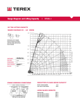
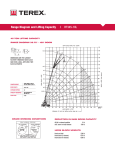
Range Diagram and Lifting Capacity
|
Cranes |
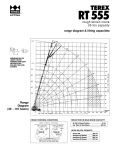
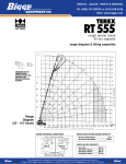
RT665
65 TON LIFTING CAPACITY
RANGE DIAGRAM 36' - 111' BOOM
DIMENSIONS ARE FOR LARGEST
FACTORY FURNISHED HOOK BLOCK
AND HOOK & BALL, WITH ANTI-TWO
BLOCK ACTIVATED
COUNTERWEIGHT
W/AUX. WINCH 13,100 LB
W/O AUX. WINCH 14,200 LB
BOOM LENGTH
36'-111'
OUTRIGGER SPREAD
24'
STABILITY PERCENTAGE
ON OUTRIGGERS 85%
ON TIRES 75%
PCSA CLASS
10-270
CRANE WORKING CONDITIONS
REDUCTION IN MAIN BOOM CAPACITY
All jib in stowed position
Aux. boom in head sheave
0 lb
100 lb
HOOK BLOCK WEIGHTS
Hook and ball
Hook block (5 sheave)
419 lb
1,204 lb
ROUGH TERRAIN CRANE
RT665
LIFTING CAPACITIES
CAUTION: Do not use this specification sheet as a load rating chart. The format of data is not consistent with
the machine chart and may be subject to change
ON OUTRIGGERS - FULLY EXTENDED
BOOM LENGTH 36’
LOAD
RADIUS
(FT)
10
12
15
20
25
30
35
40
45
50
55
60
65
70
75
80
85
90
95
100
105
110
BOOM
ANGLE
(DEG)
REF.
67.1
63.6
57.5
48.0
35.9
18.0
**
BOOM LENGTH 51’
OVER
FRONT
(LB)
360º
(LB)
130,000*
106,800*
86,100*
62,100*
47,700*
37,800*
130,000*
106,800*
85,900*
62,100*
47,700*
37,800*
BOOM
ANGLE
(DEG)
REF.
74.1
71.8
68.1
61.9
55.3
48.0
39.9
29.9
15.0
**
BOOM LENGTH 66’
OVER
FRONT
(LB)
360º
(LB)
80,100*
80,100*
78,500*
63,400*
48,900*
39,200*
32,300*
27,100*
22,200
80,100*
80,100*
78,500*
63,400*
48,900*
39,200*
32,300*
27,000
21,400
BOOM
ANGLE
(DEG)
REF.
73.3
68.7
63.9
58.9
53.7
48.0
41.9
34.8
26.2
13.2
**
OVER
FRONT
(LB)
62,000*
54,900*
49,200*
39,900*
33,000*
27,700
23,000
19,100
16,000
13,500
360º
(LB)
62,000*
54,900*
49,200*
39,900*
33,000*
27,500
2,200
18,300
15,200
12,700
LOAD
RADIUS
(FT)
10
12
15
20
25
30
35
40
45
50
55
60
65
70
75
80
85
90
95
100
105
110
USE THESE CHARTS ONLY
WHEN ALL OUTRIGGERS
ARE FULLY EXTENDED
ROUGH TERRAIN CRANE
RT665
CAUTION: Do not use this specification sheet as a load rating chart. The format of data is not consistent with
the machine chart and may be subject to change
LIFTING CAPACITIES
ON OUTRIGGERS - FULLY EXTENDED
BOOM LENGTH 81’
LOAD
RADIUS
(FT)
10
12
15
20
25
30
35
40
45
50
55
60
65
70
75
80
85
90
95
100
105
110
BOOM
ANGLE
(DEG)
REF.
72.8
69.0
65.2
61.2
57.1
52.7
48.1
43.1
37.6
31.3
23.6
11.9
**
OVER
FRONT
(LB)
46,300*
40,800*
36,100*
32,400*
28,100*
23,300
19,400
16,400
14,000
12,000
10,300
8,900
BOOM LENGTH 96’
360º
(LB)
46.300*
40,800*
36,100*
32,400*
27,900
22,500
18,600
15,600
13,200
11,300
9,600
8,200
BOOM
ANGLE
(DEG)
REF.
72.4
69.3
66.0
62.7
59.3
55.5
52.0
48.1
43.9
39.4
34.4
28.7
21.7
11.0
**
BOOM LENGTH 111’
OVER
FRONT
(LB)
360º
(LB)
35,400*
31,300*
28,100*
25,400*
23,200*
19,600
16,600
14,200
12,300
10,600
9,300
8,100
7,000
6,000
35,400*
31,300*
28,100*
25,400*
22,700
16,600
15,800
13,400
11,500
9,900
8,500
7,400
6,300
5,400
BOOM
ANGLE
(DEG)
REF.
72.2
69.4
66.7
63.8
60.9
57.9
54.7
51.5
48.1
44.5
40.7
36.6
31.9
26.7
20.1
10.2
**
OVER
FRONT
(LB)
360º
(LB)
27,600*
24,900*
22,600*
20,700*
18,900*
16,700
14,300
12,400
10,800
9,400
8,200
7,200
6,300
5,500
4,800
4,100
27,600*
24,900*
22,600*
20,700*
18,900*
15,900
13,500
11,600
10,000
8,700
7,500
6,500
5,700
4,900
4,200
3,600
LOAD
RADIUS
(FT)
10
12
15
20
25
30
35
40
45
50
55
60
65
70
75
80
85
90
95
100
105
110
**MAXIMUM CAPACITY AT 0 DEGREE BOOM ANGLE
BOOM LENGTH 36'
LOAD
OVER
RADIUS FRONT
360º
(FT)
(LB)
(LB)
31.7
20,400* 20,400*
BOOM LENGTH 51'
LOAD
OVER
RADIUS FRONT
360º
(FT)
(LB)
(LB)
46.7
12,400*
12,400*
BOOM LENGTH 66'
LOAD
OVER
RADIUS FRONT
360º
(FT)
(LB)
(LB)
61.7
8,000*
8,000*
BOOM LENGTH 81'
LOAD
OVER
RADIUS FRONT
360º
(FT)
(LB)
(LB)
76.7
5,300*
5,300*
BOOM LENGTH 96'
LOAD
OVER
RADIUS FRONT
360º
(FT)
(LB)
(LB)
91.7
3,400*
3,400*
BOOM LENGTH 111'
LOAD
OVER
RADIUS FRONT
360º
(FT)
(LB)
(LB)
106.7
2,100*
2,100*
ROUGH TERRAIN CRANE
RT665
LIFTING CAPACITIES
CAUTION: Do not use this specification sheet as a load rating chart. The format of data is not consistent with
the machine chart and may be subject to change
ON OUTRIGGERS - MID POSITION
LOAD
RADIUS
(FT)
BOOM LENGTH 36'
BOOM
ANGLE
(DEG)
360º
REF.
(LB)
10
12
15
20
25
30
35
40
45
50
55
60
65
70
75
80
67.1
63.6
57.5
48.0
35.9
18.0
**
121,200*
106,800*
86,000*
48,800
31,300
21,800
BOOM LENGTH 51'
BOOM
ANGLE
(DEG)
360º
REF.
(LB)
74.1
71.8
68.1
61.9
55.3
48.0
39.9
29.9
15.0
**
80,100*
80,100*
78,500*
49,900
32,700
23,400
17,500
13,300
10,300
BOOM LENGTH 66'
BOOM
ANGLE
(DEG)
360º
REF.
(LB)
73.3
68.7
63.9
58.9
53.7
48.0
41.9
34.8
26.2
13.2
**
BOOM LENGTH 81'
BOOM
ANGLE
(DEG)
360º
REF.
(LB)
62,000*
50,400
33,200
23,900
18,100
14,100
11,100
8,800
7,000
5,400
72.8
69.0
65.2
61.2
57.1
52.7
48.1
43.1
37.6
31.3
23.6
11.9
**
46,300*
33,500
24,200
18,300
14,300
11,400
9,200
7,400
5,900
4,700
3,700
2,800
BOOM LENGTH 96'
BOOM
ANGLE
(DEG)
360º
REF.
(LB)
72.4
69.3
66.0
62.7
59.3
55.5
52.0
48.1
43.9
39.4
34.4
28.7
**MAXIMUM CAPACITY AT 0 DEGREE BOOM ANGLE
BOOM LENGTH 36’
BOOM LENGTH 51’
BOOM LENGTH 66’
BOOM LENGTH 81’
LOAD
RADIUS
(FT)
360º
(LB)
LOAD
RADIUS
(FT)
360º
(LB)
LOAD
RADIUS
(FT)
360º
(LB)
LOAD
RADIUS
(FT)
360º
(LB)
31.7
19,200
46.7
9,300
61.7
4,900
76.7
2,500
BOOM LENGTH 96’
LOAD
RADIUS
(FT)
360º
(LB)
BOOM LENGTH 111’
LOAD
RADIUS
(FT)
360º
(LB)
33,700
24,400
18,500
14,500
11,600
9,400
7,600
6,200
5,000
4,000
3,100
2,400
BOOM LENGTH 111'
BOOM
ANGLE
(DEG)
360º
REF.
(LB)
72.2
69.4
66.7
63.8
60.9
57.9
54.7
51.5
48.1
44.5
40.7
24.500
18,600
14,600
11,700
9.500
7.800
6,300
5.200
4,200
3.300
2.600
LOAD
RADIUS
(FT
10
12
15
20
25
30
35
40
45
50
55
60
65
70
75
80
USE THESE CHARTS ONLY WHEN
ALL OUTRIGGERS ARE PINNED IN
MID POSITION
ROUGH TERRAIN CRANE
RT665
LIFTING CAPACITIES
CAUTION: Do not use this specification sheet as a load rating chart. The format of data is not consistent with
the machine chart and may be subject to change
ON OUTRIGGERS - RETRACTED
LOAD
RADIUS
(FT)
BOOM LENGTH 36'
BOOM
ANGLE
(DEG)
360º
REF.
(LB)
10
12
15
20
25
30
35
40
45
50
55
67.1
63.6
57.5
48.0
35.9
18.0
**
73,700
51,700
34,300
20,100
12,800
8,200
BOOM LENGTH 51'
BOOM
ANGLE
(DEG)
360º
REF.
(LB)
74.1
71.8
68.1
61.9
55.3
48.0
39.9
29.9
15.0
74,900
51,700
35,300
21,400
14,100
9,600
6,600
4,400
2,600
BOOM LENGTH 66'
BOOM
ANGLE
(DEG)
360º
REF.
(LB)
73.3
68.7
63.9
58.9
53.7
48.0
41.9
BOOM LENGTH 81'
BOOM
ANGLE
(DEG)
360º
REF.
(LB)
35,800
21,800
14,600
10,200
7,200
5,000
3,400
72.8
69.0
65.2
61.2
57.1
52.7
48.1
22,100
14,900
10,500
7,600
5,400
3,800
2,500
BOOM LENGTH 96'
BOOM
ANGLE
(DEG)
360º
REF.
(LB)
72.4
69.3
66.0
62.7
59.3
55.5
**MAXIMUM CAPACITY AT 0 DEGREE BOOM ANGLE
BOOM LENGTH 36’
LOAD
RADIUS
(FT)
360º
(LB)
31.7
6,800
BOOM LENGTH 51’
LOAD
RADIUS
(FT)
360º
(LB)
BOOM LENGTH 66’
LOAD
RADIUS
(FT)
360º
(LB)
BOOM LENGTH 81’
LOAD
RADIUS
(FT)
360º
(LB)
BOOM LENGTH 96’
LOAD
RADIUS
(FT)
360º
(LB)
BOOM LENGTH 111’
LOAD
RADIUS
(FT)
360º
(LB)
15,000
10,700
7,700
5,600
4,000
2,700
BOOM LENGTH 111'
BOOM
ANGLE
(DEG)
360º
REF.
(LB)
72.2
69.4
68.7
63.8
60.9
10,800
7,800
5,700
4,100
2,900
LOAD
RADIUS
(FT
10
12
15
20
25
30
35
40
45
50
55
USE THESE CHARS WHEN ALL OUTRIGGER BEAMS ARE NOT IN EITHER THE
MID OR FULLY EXTENDED POSITION
ROUGH TERRAIN CRANE
RT665
LIFTING CAPACITIES
CAUTION: Do not use this specification sheet as a load rating chart. The format of data is not consistent with
the machine chart and may be subject to change
SIDE STOW JIB ON FULLY EXTENDED OUTRIGGERS
0º OFFSET
LOADED
BOOM
ANGLE
(DEG)
LOAD
RADIUS
(REF)
(FT)
FRONT
ONLY
(LB)
75
73
71
68
65
62
59
55
51
47
43
38
32
25
17
40
46
51
58
65
71
78
86
93
100
106
113
121
127
133
12,600*
11,900*
11,300*
10,400*
9,600*
8,900*
8,300*
7,700*
7,100*
6,000
5,200
4,300
3,500
2,900
2,400
32' OFFSETTABLE JIB/NO PULL OUT INSTALLED
15º OFFSET
30º OFFSET
LOAD
LOAD
RADIUS
FRONT
RADIUS
FRONT
360º
(REF)
ONLY
360º
(REF)
ONLY
(LB)
(FT)
(LB)
(LB)
(FT)
(LB)
12,600*
11,900*
11,300*
10,400*
9,600*
8,900*
8,300*
7,700*
6,500
5,500
4,600
3,800
3,100
2,500
2,000
48
53
58
65
71
78
84
91
98
105
111
119
124
130
135
8,500*
8,200*
7,800*
7,400*
7,100*
6,800*
6,500*
6,200*
5,900*
5,500
4,800
4,100
3,400
2,800
2,300
8,500*
8,200*
7,800*
7,400*
7,100*
6,800*
6,500*
6,200*
5,900*
5,100
4,400
3,600
2,900
2,300
1,900
54
59
63
70
76
83
88
95
102
108
113
119
125
6,600*
6,400*
6,300*
6,000*
5,900*
5,700*
5,500*
5,300*
5,200*
5,000*
4,700
4,000
3,300
0º OFFSET
360º
(LB)
6,600*
6,400*
6,300*
6,000*
5,900*
5,700*
5,500*
5,300*
5,200*
5,000*
4,300
3,600
2,900
LOAD
RADIUS
(REF)
(FT)
FRONT
ONLY
(LB)
41
47
52
59
66
72
79
87
94
101
107
114
122
129
135
12,600*
11,900*
11,300*
10,400*
9,600*
8,900*
8,300*
7,600*
6,300
5,300
4,400
3,600
2,800
2,200
1,700
49' OFFSETTABLE JIB/PULL OUT RETRACTED
15º OFFSET
30º OFFSET
LOAD
LOAD
RADIUS
FRONT
RADIUS
FRONT
360º
(REF)
ONLY
360º
(REF)
ONLY
(LB)
(FT)
(LB)
(LB)
(FT)
(LB)
12,600*
11,900*
11,300*
10,400*
9,600*
8,900*
8,200*
6,800
5,700
4,700
3,900
3,100
2,300
1,800
1,300
49
54
59
66
72
79
85
92
99
106
112
120
125
132
137
8,500*
8,200*
7,800*
7,400*
7,100*
6,800*
6,500*
6,200*
5,600
4,800
4,100
3,400
2,700
2,100
1,700
8,500*
8,200*
7,800*
7,400*
7,100*
6,800*
6,500*
6,200*
5,200
4,400
3,600
2,900
2,200
1,700
1,300
55
60
64
71
77
84
89
96
103
109
114
120
126
6,600*
6,400*
6,300*
6,000*
5,900*
5,700*
5,500*
5,300*
5,200*
4,700
4,000
3,300
2,600
360º
(LB)
6,600*
6,400*
6,300*
6,000*
5,900*
5,700*
5,500*
5,300*
5,000*
4,200
3,600
2,900
2,200
LOADED
BOOM
ANGLE
(DEG)
75
73
71
68
65
62
59
55
51
47
43
38
32
25
17
ROUGH TERRAIN CRANE
RT665
LIFTING CAPACITIES
CAUTION: Do not use this specification sheet as a load rating chart. The format of data is not consistent with
the machine chart and may be subject to change
SIDE STOW JIB ON FULLY EXTENDED OUTRIGGERS
0º OFFSET
LOADED
BOOM
ANGLE
(DEG)
LOAD
RADIUS
(REF)
(FT)
FRONT
ONLY
(LB)
360º
(LB)
75
73
71
68
65
62
59
55
51
47
43
38
32
25
17
52
58
64
73
81
89
96
105
114
122
129
137
145
153
159
6,600*
6,200*
5,900*
5,600*
5,200*
4,800*
4,500*
4,100*
3,800*
3,500*
3,300*
2,700
2,200
1,600
1,200
6,600*
6,200*
5,900*
5,600*
5,200*
4,800*
4,500*
4,100*
3,800*
3,500*
3,000
2,400
1,800
1,300
1,000
57' OFFSETTABLE JIB
15º OFFSET
LOAD
RADIUS
FRONT
(REF)
ONLY
360º
(FT)
(LB)
(LB)
64
70
76
83
91
98
105
113
121
128
135
142
149
155
160
4,600*
4,400*
4,200*
3,900*
3,700*
3,500*
3,400*
3,200*
3,000*
2,900*
2,800*
2,600
2,100
1,600
1,200
4,600*
4,400*
4,200*
3,900*
3,700*
3,500*
3,400*
3,200*
3,000*
2,900*
2,800*
2,200
1,700
1,200
900
30º OFFSET
LOAD
RADIUS
(REF)
(FT)
FRONT
ONLY
(LB)
360º
(LB)
74
80
85
92
99
106
112
119
126
132
138
144
149
3,400*
3,300*
3,200*
3,100*
3,000*
2,900*
2,800*
2,700*
2,700*
2,600*
2,600*
2,500
2,000
3,400*
3,300*
3,200*
3,100*
3,000*
2,900*
2,800"
2,700"
2,700*
2,600*
2,600*
2,200
1,700
LOADED
BOOM
ANGLE
(DEG)
75
73
71
68
65
62
59
55
51
47
43
38
32
25
17
Notes For Jib Capacities:
A. For all boom lengths less than the maximum with a jib erected, the rated loads are
determined by boom angle only In the appropriate column.
B. For boom angle not shown, use the capacity of the next lower boom angle.
C. Listed radii are for extended main boom only.
ON TIRES
RADIUS
(FT)
10
12
15
20
25
30
35
40
45
50
55
60
65
75
MAX
BOOM
LENGTH
(FT)
36
36
36
36
51
51
51
51
66
66
66
81
81
81
29.5 X 25 28 PR
STATIONARY
STATIC
360º
55,700
42,800
29,500
17,600
11,800
8,000
5,700
4,100
2,900
1,900
87,600*
77,300*
61,400
37,300
22,600
15,700
12,700
10,200
8,100
6,500
5,200
4,200
3,400
2,700
PICK & CARRY
CREEP
2.5 MPH
STRAIGHT OVER FRONT
68,800
51,900
60,500
45,400
50,800
37,700
37,300
28,800
22,600
22,600
15,700
15,700
12,700
12,700
10,200
10,200
8,100
8,100
6,500
6,500
5,200
5,200
4,200
4,200
3,400
3,400
2,700
2,700
Notes For On Tire Capacities:
A. For Pick and Carry operations, boom must be centered over the front of the crane with swing
brake and lock engaged. Use minimum boom point height and keep load close to ground surface.
B. The load should be restrained from swinging. NO ON TIRE OPERATION WITH JIB ERECTED.
C. Without outriggers, never maneuver the boom beyond listed load radii for applicable tires to
ensure stability.
D. Creep speed is crane movement of less than 200' (61 m) in a 30 minute period and not
exceeding 1.0 mph (1.6 km/h).
E. Refer to General Notes for additional information.
RECOMMENDED TIRE PRESSURE
TIRE SIZE
STATIONARY
CREEP
2 1/2 MPH
TRAVEL
29.5 x 25-28 PR
81 PSI
81 PSI
65 PSI
55 PSI
MAXIMUM PERMISSIBLE HOIST LINE LOAD
LINE PARTS
MAIN & AUX. HOIST
1
13,800
WIRE ROPE:
2
27,600
3
41,400
4
55,200
5
69,000
6
82,800
7
96,600
8
100,400
9
124,200
10
130,000
3/4" ROTATION RESISTANT 34X7 COMPACTED STRAND, GRADE 2160, MINIMUM BREAKING STRENGTH - 34.5 TONS.
3/4" 6X19 OR 6X37, IPS, IWRC, PERFORMED RIGHT REGULAR LAY MINIMUM BREAKING STRENGTH - 25.6 TONS.
WEIGHT 1.04 LB/FT.
General Notes
|
Cranes |
RT600 Series
GENERAL
1.
Rated loads as shown on Lift Charts pertain to this machine as originally manufactured and equipped. Modifications to the machine or use of optional equipment or
other than that specified can result in a reduction of capacity.
2.
Construction equipment can be hazardous if improperly operated or maintained.
Operation and maintenance of this machine shall be in compliance with the information in the Operator’s, Parts and Safety Manuals supplied with this machine. If
These manuals are missing, order replacements from the manufacturer through
your distributor.
3.
These warnings to not constitute all of the operating conditions for the crane. The
operator and job site supervision must read the OPERATORS MANUAL, CIMA SAFETY MANUAL, APPLICABLE OSHA REGULATIONS, AND SOCIETY OF MECHANICAL
ENGINEERS (ASME) SAFETY STANDINGS FOR CRANES.
4.
This crane and its load ratings are in accordance with POWER CRANE & SHOVEL
ASSOCIATION, STANDARD NO.4 SAE CRANE LOAD STABILITY TEST CODE J765A,
SAE METHOD OF TEST FOR CRANE STRUCTURE J1063 AND APPLICABLE SAFETY
CODE FOR CRANES, DERRICKS AND HOISTS, ASME/ANSI B30.5
DEFINITIONS
1.
LOAD RADIUS - The horizontal distance from the axis of rotation before loading to
the center of the vertical hoist line or tackle with a load applied.
2.
LOADED BOOM ANGLE - It is the angle between the boom base section and the horizontal, after lifting the rated load at the rated radius. the boom angle before loading
should be greater to account for deflections. The loaded boom angle combined with
boom length give only an approximation of the operating radius.
3.
WORKING AREA - Areas measured in a circular arc about the centerline of rotation
as shown in the diagram.
4.
FREELY SUSPENDED LOAD - Load hanging free with no direct external force applied
except by the hoist rope.
5.
SIDE LOAD - Horizontal force applied to he lifted load either on the ground or in the
air.
6.
NO LOAD STABILITY LIMIT - The stability limit radius shown on the range diagrams
is the radius beyond which it is not permitted to position the boom, when the boom
angle is less than the minimum shown on the applicable load chart, because the
machine can overturn without any load.
7.
BOOM SIDE OF CRANE - The side of the crane over which the boom is positions
when in OVER SIDE working position.
SET-UP
1.
Crane load ratings are based on the crane being leveled and standing on a firm,
uniform supporting surface.
2.
Crane load ratings on outriggers are based on all outrigger beams being fully
extended or in the case of partial extension ratings mechanically pinned in the
appropriate position, and the tires free of the supporting surface.
3.
Crane load ratings on tires depend on appropriate inflation pressure and the tire
conditions. Caution must be exercised when increasing air pressures in tires.
Consult Operator’s Manual for precautions.
4.
Use of jibs, lattice-type boom extensions, or fourth section pullouts extended is not
permitted for pick and carry operations.
5.
Consult appropriate section of the Operator’s and Service Manual for more exact
description of hoist line reeving.
6.
The use of more parts of line than required by the load may result in having insufficient rope to allow the hook block to reach the ground.
7.
Properly maintained wire rope is essential for save crane operation. Consult
Operator’s Manual for proper maintenance and inspection requirements.
8.
When spin-resistant wire rope is used, the allowable rope loading shall be the
breaking strength divided by five (5), unless otherwise specified by the wire rope
manufacturer.
9.
Do not elevate the boom above 60° unless the boom is positioned in-line with the
crane’s chassis or the outrigger are extended. Failure to observe this warning may
result in loss of stability.
TEREX Cranes
106-12th Street S.E.
Waverly, Iowa 50677-9466 USA
OPERATION
1.
CRANE LOAD RATINGS MUST NOT BE EXCEEDED. DO NOT ATTEMPT TO TIP THE
CRANE TO DETERMINE ALLOWABLE LOADS.
2.
When either radius or boom length, or both, are between listed values, the smaller
of the two listed load ratings shall be used.
3.
Do not operate at longer radii than those listed on the applicable load rating chart
(cross hatched areas shown on range diagrams.)
4.
The boom angles shown on the Capacity Chart give an approximation of the operating radius for a specified boom length.The boom angle, before loading, should be
greater to account for boom deflection. It may be necessary to retract the boom if
maximum boom angle is insufficient to maintain rated radius.
5.
Power telescoping boom sections must be extended equally.
6.
Rated loads include the weight of hook block, slings, and auxiliary lifting devices.
Their weights shall be subtracted from the listed rated load to obtain the net load
that can be lifted. When lifting over the jib the weight of any hook block, slings, and
auxiliary lifting devices at the boom head must be added to the load. When jibs are
erected but unused add two (2) times the weight of any hook block, slings, and
auxiliary lifting devices at the jib head to the load.
7.
Rated loads do not exceed 85% on outriggers or 75% on tires, of the tipping load
as determined by SAE Crane Stability Test Code J765a. Structural strength ratings
in chart are indicated with an asterisk (*).
8.
Rated loads are based on freely suspended loads. No attempt shall be made to drag
a load horizontally on the ground in any direction.
9.
The user shall operate at reduced ratings to allow for adverse job conditions, such
as: soft or uneven ground, out of level conditions, high winds, side loads, pendulum
action, jerking or sudden stopping of loads, hazardous conditions, experience of
personnel, two machine lifts, traveling with loads, electric wires, etc. (side pull on
boom or jib is hazardous). Derating of the cranes lifting capacity is required when
wind speed exceeds 20 MPH. The center of the lifted load must never be allowed to
move more then 3* off the center line of the base boom section due to the effects
of wind, inertia, or any combination of the two.
*"Use 2' off the center line of the base boom for a two section boom, 3' for a there
section boom, or 4’ for a four section boom.”
10. The maximum load which can be telescoped is not definable, because of variations
in loadings and crane maintenance, but it is permissible to attempt retraction and
extension if load ratings are not exceeded.
11. Load ratings are dependent upon the crane being maintained according to manufacturer's specifications.
12. It is recommended that load handling devices, including hooks, and hook blocks, be
kept away from boom head at all times.
13. FOR TRUCK CRANES ONLY: 360° capacities apply only to machines equipped with a
front outrigger jack and all five(5) outrigger jacks properly set. If the front (5th) outrigger jack is not properly set, the work area is restricted to the over side and over
rear ares as shown on the Crane Working Positions diagram. Use the 360° load ratings in the overside work areas.
14. Do not lift with outrigger beams positioned between the fully extended and intermediate (pinned) positions.
15. Truck Cranes not equipped with equalizing (bogie) beams between the rear axles
may not be used for lifting “on tires”. Truck Cranes equipped with equalizing beams
and rear air suspension should “dump” the air before lifting “on tires”.
CLAMSHELL, MAGNET, AND CONCRETE BUCKET SERVICE
1.
Maximum boom length for clamshell and magnet service is 50'.
2.
Weight of clamshell or magnet, plus contents are not to exceed 6,000 lb or 90% of
rated lifting capacities, whichever is less. For concrete bucket operation, weight of
bucket and load must not exceed 90% of rated lifting capacity.
TEL (319) 352-3920 FAX (319) 352-5727
EMAIL [email protected]
WEB terex.com
WE RESERVE THE RIGHT TO AMEND THESE SPECIFICATIONS AT ANY TIME WITHOUT NOTICE. THE ONLY WARRANTY APPLICABLE IS OUR STANDARD WRITTEN WARRANTY APPLICABLE TO THE PARTICULAR PRODUCT AND SALE.
WE MAKE NO OTHER WARRANTY, EXPRESSED OR IMPLIED.
©TEREX CRANES, INC 2005
PRINTED IN U.S.A
MARCH 7, 2005