1
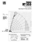
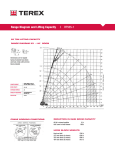
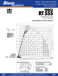
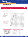
Range Diagram and Lifting Capacity
|
Cranes |
RT345-1XL
45 TON LIFTING CAPACITY
RANGE DIAGRAM 33.75' - 105' BOOM
DIMENSIONS ARE FOR LARGEST
FACTORY FURNISHED HOOK BLOCK
AND HOOK & BALL, WITH ANTI-TWO
BLOCK ACTIVATED
COUNTER WEIGHT
W/AUX. WINCH 11,900 LB
W/O AUX. WINCH 13,000 LB
BOOM LENGTH
33.75'-105'
OUTRIGGER SPREAD
22'
STABILITY PERCENTAGE
ON OUTRIGGERS 85%
ON TIRES 75%
PCSA CLASS
9-169
CRANE WORKING CONDITIONS
REDUCTION IN MAIN BOOM CAPACITY
All jib in stowed position
Aux. boom in head sheave
0 lb
100 lb
HOOK BLOCK WEIGHTS
Hook and ball
Hook block (3 sheave)
Hook block (4 sheave)
239 lb
670 lb
690 lb
ROUGH TERRAIN CRANE
RT345-1XL
CAUTION: Do not use this specification sheet as a load rating chart. The format of data is not consistent with
the machine chart and may be subject to change
LIFTING CAPACITIES
ON OUTRIGGERS - FULLY EXTENDED
BOOM LENGTH 33.75’
LOADED
BOOM
OVER
ANGLE
FRONT
360º
(DEG)
(LB)
(LB)
LOAD
RADIUS
(FT)
9
10
12
15
20
25
30
35
40
45
50
55
60
65
70
75
80
85
90
95
100
105
LOAD
RADIUS
(FT)
9
10
12
15
20
25
30
35
40
45
50
55
60
65
70
75
80
85
90
95
100
105
68.1
66.0
62.1
56.1
44.8
30.2
90,000
64,400
58,000
50,700
40,400
30,600
BOOM LENGTH 69’
LOADED
BOOM
OVER
ANGLE
FRONT
360º
(DEG)
(LB)
(LB)
74.3
69.9
65.4
60.7
55.8
50.5
44.8
38.4
31.0
21.3
41,600
34,800
29,400
25,600
21,300
17,800
15,100
12,900
11,100
9,500
41,600
34,800
29,400
25,600
21,300
17,800
15,100
12,900
11,100
9,500
BOOM LENGTH 45’
OVER
FRONT
(LB)
360º
(LB)
72.3
69.6
65.4
58.1
50.1
40.9
29.5
8.4
46,500
46,500
46,500
38,800
31,600
25,000
20,300
16,700
46,500
46,500
46,500
38,800
31,600
25,000
20,300
16,700
90,000
64,400
58,000
50,700
40,400
30,600
BOOM LENGTH 81’
LOADED
BOOM
OVER
ANGLE
FRONT
360º
(DEG)
(LB)
(LB)
73.0
69.2
65.4
61.4
57.3
52.9
48.3
43.3
37.7
31.4
23.5
11.1
30,660
26,000
22,500
19,600
17,400
15,300
13,100
11,300
9,800
8,500
7,400
6,500
LOADED
BOOM
ANGLE
(DEG)
72.0
68.7
65.4
61.9
58.3
54.6
50.7
46.6
42.1
37.2
31.7
25.1
16.0
23,400
20,300
17,700
15,600
14,100
12,600
11,500
10,000
8,700
7,600
6,700
5,800
5,000
OVER
FRONT
(LB)
74.0
70.8
65.4
59.7
53.6
46.9
39.4
30.4
17.5
BOOM LENGTH 93’
LOADED
BOOM
OVER
ANGLE
FRONT
360º
(DEG)
(LB)
(LB)
30,660
26,000
22,500
19,600
17,400
15,300
13,100
11,300
9,800
8,400
7,200
6,100
USE THESE CHARTS ONLY
WHEN ALL OUTRIGGERS
ARE FULLY EXTENDED
BOOM LENGTH 57’
LOADED
BOOM
ANGLE
(DEG)
23,400
20,300
17,700
15,600
14,100
12,600
11,500
9,900
8,500
7,300
6,300
5,500
4,700
46,500
44,500
36,400
31,000
25,600
20,900
17,400
14,700
12,400
360º
(LB)
18,600
16,200
14,400
12,900
11,600
10,400
9,500
8,800
7,800
6,800
6,000
5,200
4,500
3,900
3,300
9
10
12
15
20
25
30
35
40
45
50
55
60
65
70
75
80
85
90
95
100
105
46,500
44,500
36,400
31,000
25,600
20,900
17,400
14,700
12,400
BOOM LENGTH 105'
LOADED
BOOM
OVER
ANGLE
FRONT
360º
(DEG)
(LB)
(LB)
71.3
68.4
65.4
62.3
59.2
55.9
52.5
49.0
45.2
41.2
36.8
31.9
26.2
18.9
5.2
LOAD
RADIUS
(FT)
18,600
16,200
14,400
12,900
11,600
10,400
9,500
8,600
7,400
6,400
5,600
4,800
4,200
3,600
3,100
LOAD
RADIUS
(FT)
9
10
12
15
20
25
30
35
40
45
50
55
60
65
70
75
80
85
90
95
100
105
**MAXIMUM CAPACITY AT 0 DEGREE BOOM ANGLE
BOOM LENGTH 33.75 FT
LOAD
OVER
RADIUS FRONT
360º
(FT)
(LB)
(LB)
29.1
24,800
24,800
BOOM LENGTH 45 FT
LOAD
OVER
RADIUS FRONT
360º
(FT)
(LB)
(LB)
40.3
16,400
16,400
BOOM LENGTH 57 FT
LOAD
OVER
RADIUS FRONT
360º
(FT)
(LB)
(LB)
52.3
11,500
11,500
BOOM LENGTH 69 FT
LOAD
OVER
RADIUS FRONT
360º
(FT)
(LB)
(LB)
64.3
8,300
8,200
BOOM LENGTH 81 FT
LOAD
OVER
RADIUS FRONT
360º
(FT)
(LB)
(LB)
76.3
6,200
5,800
BOOM LENGTH 93 FT
LOAD
OVER
RADIUS FRONT
360º
(FT)
(LB)
(LB)
88.3
4,500
4,200
BOOM LENGTH 105 FT
LOAD
OVER
RADIUS FRONT 360º
(FT)
(LB)
(LB)
100.3
3,300
3,300
ROUGH TERRAIN CRANE
RT345-1XL
LIFTING CAPACITIES
CAUTION: Do not use this specification sheet as a load rating chart. The format of data is not consistent with
the machine chart and may be subject to change
ON OUTRIGGERS - RETRACTED
LOAD
RADIUS
(FT)
BOOM LENGTH 33.75 FT
LOADED
BOOM
ANGLE
360º
(DEG)
(LB)
9
10
12
15
20
25
30
35
40
45
50
55
LOAD
RADIUS
(FT)
66.0
62.1
56.1
44.8
30.2
62,100
43,500
29,000
17,100
10,900
BOOM LENGTH 69 FT
LOADED
BOOM
ANGLE
360º
(DEG)
(LB)
9
10
12
15
20
25
30
35
40
45
50
55
60
65
70
74.3
69.9
65.4
60.7
55.8
50.5
44.8
38.4
31.0
30,600
18,800
12,700
9,000
6,600
4,700
3,300
2,300
1,400
BOOM LENGTH 45 FT
LOADED
BOOM
ANGLE
360º
(DEG)
(LB)
72.3
69.6
65.4
58.1
50.1
40.9
29.5
8.4
46,500
44,500
29,800
18,100
11,900
8,200
5,600
3,700
BOOM LENGTH 81 FT
LOADED
BOOM
ANGLE
360º
(DEG)
(LB)
73.0
69.2
65.4
61.4
57.3
52.9
48.3
43.3
19,000
12,900
9,200
6,700
5,000
3,600
2,500
1,600
BOOM LENGTH 57 FT
LOADED
BOOM
ANGLE
360º
(DEG)
(LB)
74.0
70.8
65.4
59.7
53.6
46.9
39.4
30.4
17.5
LOAD
RADIUS
(FT)
9
10
12
15
20
25
30
35
40
45
50
55
45,00
30,300
18,500
12,500
8,700
6,200
4,400
3,000
1,900
BOOM LENGTH 93 FT
LOADED
BOOM
ANGLE
360º
(DEG)
(LB)
72.0
68.7
65.4
61.9
58.3
54.6
50.7
46.6
USE THESE CHARTS WHEN ALL
OUTRIGGER BEAMS ARE NOT IN
EITHER THE MID OR FULLY
EXTENDED POSITION
BOOM LENGTH 105 FT
LOADED
BOOM
ANGLE
360º
(DEG)
(LB)
13,000
9,300
6,900
5,100
3,700
2,700
1,800
1,100
71.3
68.4
65.4
62.3
59.2
55.9
52.5
LOAD
RADIUS
(FT)
9
10
12
15
20
25
30
35
40
45
50
55
60
65
70
9,400
6,900
5,200
3,800
2,800
1,900
1,200
**MAXIMUM CAPACITY AT 0 DEGREE BOOM ANGLE
BOOM LENGTH 33.75 FT BOOM LENGTH 45 FT
BOOM LENGTH 57 FT
BOOM LENGTH 69 FT
BOOM LENGTH 81 FT
BOOM LENGTH 93 FT
BOOM LENGTH 105 FT
LOAD
RADIUS
(FT)
360º
(LB)
LOAD
RADIUS
(FT)
360º
(LB)
LOAD
RADIUS
(FT)
360º
(LB)
LOAD
RADIUS
(FT)
360º
(LB)
LOAD
RADIUS
(FT)
360º
(LB)
LOAD
RADIUS
(FT)
360º
(LB)
LOAD
RADIUS
(FT)
360º
(LB)
29.1
7,500
40.3
3,500
52.3
1,300
--
--
--
--
--
--
--
--
ROUGH TERRAIN CRANE
RT345-1XL
LIFTING CAPACITIES
CAUTION: Do not use this specification sheet as a load rating chart. The format of data is not consistent with
the machine chart and may be subject to change
SIDE STOW JIB ON FULLY EXTENDED OUTRIGGERS
RATED ON OUTRIGGERS WITH 32 FT OFFSETABLE JIB
0º OFFSET
15º OFFSET
30º OFFSET
LOAD
LOAD
LOAD
RADIUS
RADIUS
RADIUS
(REF)
360º
(REF)
360º
(REF)
360º
(FT)
(LB)
(FT)
(LB)
(FT)
(LB)
LOADED
BOOM
ANGLE
(DEG)
75
73
71
68
65
62
59
55
51
47
43
38
32
25
49
50
51
59
66
72
78
86
92
97
103
109
116
123
9,100
8,700
8,300
7,700
7,100
6,500
6,000
5,200
4,400
3,600
2,900
2,200
1,500
1,000
59
60
62
68
74
79
84
91
97
103
108
114
121
127
8,300
8,000
7,600
7,200
6,900
6,500
5,900
4,900
4,100
3,300
2,700
2,000
1,500
1,100
65
66
68
73
78
83
88
94
100
105
109
115
120
126
6,400
6,200
6,100
5,800
5,700
5,500
5,300
4,500
3,800
3,200
2,600
2,000
1,500
1,100
RATED ON OUTRIGGERS WITH 49 FT OFFSETABLE JIB
0º OFFSET
15º OFFSET
30º OFFSET
LOAD
LOAD
LOAD
RADIUS
RADIUS
RADIUS
(REF)
360º
(REF)
360º
(REF)
360º
(FT)
(LB)
(FT)
(LB)
(FT)
(LB)
65
67
68
75
81
87
92
99
106
113
119
126
133
141
4,900
4,600
4,300
3,900
3,600
3,400
3,200
2,900
2,700
2,600
2,500
2,000
1,500
1,100
62
67
72
79
86
92
98
106
112
119
124
131
137
142
3,200
3,100
3,000
2,800
2,700
2,600
2,500
2,400
2,300
2,200
2,100
1,900
1,500
1,100
65
70
75
82
89
96
102
109
116
121
127
132
136
140
2,500
2,500
2,400
2,300
2,300
2,200
2,200
2,100
2,100
2,000
2,000
1,700
1,300
900
LOADED
BOOM
ANGLE
(DEG)
USE THESE CHARTS ONLY
WHEN ALL OUTRIGGERS
ARE FULLY EXTENDED
75
73
71
68
65
62
59
550
51
47
43
38
32
25
Notes For Jib Capacities:
A. For all boom lengths less than the maximum with a jib erected, the rated loads are determined by boom angle only In the appropriate column.
B. For boom angle not shown, use the capacity of the next lower boom angle.
C. Listed radii are for extended main boom only.
ON TIRES
RADIUS
(FT)
10
12
15
20
25
30
35
40
45
50
55
60
65
70
75
MAX
BOOM
LENGTH
(FT)
33.75
33.75
45
45
45
45
57
57
57
69
69
81
81
81
93
Notes For On Tire Capacities:
26.5 X 25-26 PR
STATIONARY
360º
34,200
64,500*
28,300
56,200*
21,300
46,800*
13,100
30,300
8,300
20,300
5,700
14,600
4,100
11,200
3,000
8,700
2,200
7,000
1,500
5,700
4,600
3,800
2,900
2,100
1,300
PICK & CARRY
CREEP
2.5 MPH
STRAIGHT OVER FRONT
48,600*
40,600*
42,100*
33,300
34,800*
28,700*
26,400*
21,500*
20,300
16,500*
14,600
12,900*
11,200
10,700*
8,700
8,700
7,000
7,000
5,700
5,700
4,600
4,600
3,800
3,800
2,900
2,900
2,100
2,100
1,300
1,300
A. For Pick and Carry operations, boom must be
centered over the front of the crane with swing
brake and lock engaged. Use minimum boom
point height and keep load close to ground surface.
B. The load should be restrained from swinging.
NO ON TIRE OPERATION WITH JIB ERECTED.
C. Without outriggers, never maneuver the boom
beyond listed load radii for applicable tires to
ensure stability.
D. Creep speed is crane movement of less than
200' (61m) in a 30 minute period and not
exceeding 1.0 mph (1.6 km/h).
E. Refer General Notes for additional information.
RECOMMENDED TIRE PRESSURE
TIRE SIZE
STATIONARY
CREEP
2 1/2 MPH
TRAVEL
26.5 x 25-26 PR
65 PSI
65 PSI
65 PSI
50 PSI
MAXIMUM PERMISSIBLE HOIST LINE LOAD
LINE PARTS
MAX. LOAD
BOOM HEAD
HOOK BLOCK
1
2
3
4
5
6
9,080
18,160
27,240
36,320
45,400
54,480
2
3-D
2-3
1-4-D
2-3-4
2-3-4-D
0
3
3-D
1-4
2-3-D
2-3-4
WIRE ROPE:
5/8' ROTATION RESISTANT COMPACTED STRAND, 18X19
OR 19X19 MINIMUM BREAKING STRENGTH - 22.7 TONS
5/8' 6X19 OR 6X37 IWPC IPS PREFORMED RIGHT
REGULAR LAY MINIMUM BREAKING STRENGTH - 17.9 TONS
7
63,560
1-2-3-4
2-3-4-D
8
72,640
1-2-3-4-D
1-2-3-4
9
10
80,000
80,000
1-2-3-4-5 1-2-3-4-5-D
1-2-3-4-D 1-2-3-4-5
ROUGH TERRAIN CRANE
RT345-1XL
LIFTING CAPACITIES
CAUTION: Do not use this specification sheet as a load rating chart. The format of data is not consistent with
the machine chart and may be subject to change
ON OUTRIGGERS - MID POSITION
LOAD
RADIUS
(FT)
BOOM LENGTH 33.75 FT
LOADED
BOOM
ANGLE
360º
(DEG)
(LB)
9
10
12
15
20
25
30
35
40
45
50
55
60
65
70
LOAD
RADIUS
(FT)
68.1
66.0
62.1
56.1
44.8
30.2
80,000
64,400
58,000
50,700
36,600
23,700
BOOM LENGTH 69 FT
LOADED
BOOM
ANGLE
360º
(DEG)
(LB)
9
10
12
15
20
25
30
35
40
45
50
55
60
65
70
75
80
85
90
74.3
69.9
65.4
60.7
55.8
50.5
44.8
38.4
31.0
41,600
34,800
25,500
18,400
10,900
8,600
6,900
5,400
4,300
BOOM LENGTH 45 FT
LOADED
BOOM
ANGLE
360º
(DEG)
(LB)
72.3
69.6
65.4
58.1
50.1
40.9
29.5
8.4
46,500
46,500
46,500
37,500
24,700
17,700
13,100
9,800
BOOM LENGTH 81 FT
LOADED
BOOM
ANGLE
360º
(DEG)
(LB)
73.0
69.2
65.4
61.4
57.3
52.9
48.3
43.3
37.7
31.4
23.5
11.1
30,600
25,700
18,600
14,200
11,100
8,800
7,100
5,700
4,600
3,600
2,800
2,100
BOOM LENGTH 57 FT
LOADED
BOOM
ANGLE
360º
(DEG)
(LB)
74.0
70.8
65.4
59.7
53.6
46.9
39.4
30.4
17.5
LOAD
RADIUS
(FT)
46,500
44,500
36,400
25,200
18,200
13,700
10,600
8,200
6,400
5,600
BOOM LENGTH 93 FT
LOADED
BOOM
ANGLE
360º
(DEG)
(LB)
72.0
68.7
65.4
61.9
58.3
54.6
50.7
46.6
42.1
37.2
31.7
25.1
16.0
9
10
12
15
20
25
30
35
40
45
50
55
60
65
70
USE THESE CHARTS ONLY WHEN
ALL OUTRIGGERS ARE PINNED IN
MID POSITION
BOOM LENGTH 105 FT
LOADED
BOOM
ANGLE
360º
(DEG)
(LB)
23,400
18,800
14,300
11,200
8,900
7,200
5,800
4,700
3,800
3,000
2,300
1,800
1,200
71.3
68.4
65.4
62.3
59.2
55.9
52.5
49.0
45.2
41.2
36.8
31.9
LOAD
RADIUS
(FT)
9
10
12
15
20
25
30
35
40
45
50
55
60
65
70
75
80
85
90
18,600
14,400
11,300
9,000
7,300
5,900
4,800
3,900
3,100
2,500
1,900
1,400
**MAXIMUM CAPACITY AT 0 DEGREE BOOM ANGLE
BOOM LENGTH 33.75 FT BOOM LENGTH 45 FT
BOOM LENGTH 57 FT
BOOM LENGTH 69 FT
BOOM LENGTH 81 FT
BOOM LENGTH 93 FT
LOAD
RADIUS
(FT)
360º
(LB)
LOAD
RADIUS
(FT)
LOAD
RADIUS
(FT)
360º
(LB)
LOAD
RADIUS
(FT)
360º
(LB)
LOAD
RADIUS
(FT)
360º
(LB)
LOAD
RADIUS
(FT)
360º
(LB)
LOAD
RADIUS
(FT)
360º
(LB)
29.1
17,300
40.3
52.3
5,600
64.3
3,400
76.3
1,900
--
--
--
--
360º
(LB)
9,600
BOOM LENGTH 105 FT
Notes
Notes
General Notes
|
Cranes |
RT300 Series
GENERAL
1.
Rated loads as shown on Lift Charts pertain to this machine as originally manufactured and equipped. Modifications to the machine or use of optional equipment or
other than that specified can result in a reduction of capacity.
2.
Construction equipment can be hazardous if improperly operated or maintained.
Operation and maintenance of this machine shall be in compliance with the information in the Operator’s, Parts and Safety Manuals supplied with this machine. If
These manuals are missing, order replacements from the manufacturer through
your distributor.
3.
These warnings to not constitute all of the operating conditions for the crane. The
operator and job site supervision must read the OPERATORS MANUAL, CIMA SAFETY MANUAL, APPLICABLE OSHA REGULATIONS, AND SOCIETY OF MECHANICAL
ENGINEERS (ASME) SAFETY STANDINGS FOR CRANES.
4.
This crane and its load ratings are in accordance with POWER CRANE & SHOVEL
ASSOCIATION, STANDARD NO.4 SAE CRANE LOAD STABILITY TEST CODE J765A,
SAE METHOD OF TEST FOR CRANE STRUCTURE J1063 AND APPLICABLE SAFETY
CODE FOR CRANES, DERRICKS AND HOISTS, ASME/ANSI B30.5
DEFINITIONS
1.
LOAD RADIUS - The horizontal distance from the axis of rotation before loading to
the center of the vertical hoist line or tackle with a load applied.
2.
LOADED BOOM ANGLE - It is the angle between the boom base section and the horizontal, after lifting the rated load at the rated radius. the boom angle before loading
should be greater to account for deflections. The loaded boom angle combined with
boom length give only an approximation of the operating radius.
3.
WORKING AREA - Areas measured in a circular arc about the centerline of rotation
as shown in the diagram.
4.
FREELY SUSPENDED LOAD - Load hanging free with no direct external force applied
except by the hoist rope.
5.
SIDE LOAD - Horizontal force applied to he lifted load either on the ground or in the
air.
6.
NO LOAD STABILITY LIMIT - The stability limit radius shown on the range diagrams
is the radius beyond which it is not permitted to position the boom, when the boom
angle is less than the minimum shown on the applicable load chart, because the
machine can overturn without any load.
7.
BOOM SIDE OF CRANE - The side of the crane over which the boom is positions
when in OVER SIDE working position.
SET-UP
1.
Crane load ratings are based on the crane being leveled and standing on a firm,
uniform supporting surface.
2.
Crane load ratings on outriggers are based on all outrigger beams being fully
extended or in the case of partial extension ratings mechanically pinned in the
appropriate position, and the tires free of the supporting surface.
3.
Crane load ratings on tires depend on appropriate inflation pressure and the tire
conditions. Caution must be exercised when increasing air pressures in tires.
Consult Operator’s Manual for precautions.
4.
Use of jibs, lattice-type boom extensions, or fourth section pullouts extended is not
permitted for pick and carry operations.
5.
Consult appropriate section of the Operator’s and Service Manual for more exact
description of hoist line reeving.
6.
The use of more parts of line than required by the load may result in having insufficient rope to allow the hook block to reach the ground.
7.
Properly maintained wire rope is essential for save crane operation. Consult
Operator’s Manual for proper maintenance and inspection requirements.
8.
When spin-resistant wire rope is used, the allowable rope loading shall be the
breaking strength divided by five (5), unless otherwise specified by the wire rope
manufacturer.
9.
Do not elevate the boom above 60° unless the boom is positioned in-line with the
crane’s chassis or the outrigger are extended. Failure to observe this warning may
result in loss of stability.
TEREX Cranes
106-12th Street S.E.
Waverly, Iowa 50677-9466 USA
OPERATION
1.
CRANE LOAD RATINGS MUST NOT BE EXCEEDED. DO NOT ATTEMPT TO TIP THE
CRANE TO DETERMINE ALLOWABLE LOADS.
2.
When either radius or boom length, or both, are between listed values, the smaller
of the two listed load ratings shall be used.
3.
Do not operate at longer radii than those listed on the applicable load rating chart
(cross hatched areas shown on range diagrams.)
4.
The boom angles shown on the Capacity Chart give an approximation of the operating radius for a specified boom length.The boom angle, before loading, should be
greater to account for boom deflection. It may be necessary to retract the boom if
maximum boom angle is insufficient to maintain rated radius.
5.
Power telescoping boom sections must be extended equally.
6.
Rated loads include the weight of hook block, slings, and auxiliary lifting devices.
Their weights shall be subtracted from the listed rated load to obtain the net load
that can be lifted. When lifting over the jib the weight of any hook block, slings, and
auxiliary lifting devices at the boom head must be added to the load. When jibs are
erected but unused add two (2) times the weight of any hook block, slings, and
auxiliary lifting devices at the jib head to the load.
7.
Rated loads do not exceed 85% on outriggers or 75% on tires, of the tipping load
as determined by SAE Crane Stability Test Code J765a. Structural strength ratings
in chart are indicated with an asterisk (*).
8.
Rated loads are based on freely suspended loads. No attempt shall be made to drag
a load horizontally on the ground in any direction.
9.
The user shall operate at reduced ratings to allow for adverse job conditions, such
as: soft or uneven ground, out of level conditions, high winds, side loads, pendulum
action, jerking or sudden stopping of loads, hazardous conditions, experience of
personnel, two machine lifts, traveling with loads, electric wires, etc. (side pull on
boom or jib is hazardous). Derating of the cranes lifting capacity is required when
wind speed exceeds 20 MPH. The center of the lifted load must never be allowed to
move more then 3* off the center line of the base boom section due to the effects
of wind, inertia, or any combination of the two.
*"Use 2' off the center line of the base boom for a two section boom, 3' for a there
section boom, or 4’ for a four section boom.”
10. The maximum load which can be telescoped is not definable, because of variations
in loadings and crane maintenance, but it is permissible to attempt retraction and
extension if load ratings are not exceeded.
11. Load ratings are dependent upon the crane being maintained according to manufacturer's specifications.
12. It is recommended that load handling devices, including hooks, and hook blocks, be
kept away from boom head at all times.
13. FOR TRUCK CRANES ONLY: 360° capacities apply only to machines equipped with a
front outrigger jack and all five(5) outrigger jacks properly set. If the front (5th) outrigger jack is not properly set, the work area is restricted to the over side and over
rear ares as shown on the Crane Working Positions diagram. Use the 360° load ratings in the overside work areas.
14. Do not lift with outrigger beams positioned between the fully extended and intermediate (pinned) positions.
15. Truck Cranes not equipped with equalizing (bogie) beams between the rear axles
may not be used for lifting “on tires”. Truck Cranes equipped with equalizing beams
and rear air suspension should “dump” the air before lifting “on tires”.
CLAMSHELL, MAGNET, AND CONCRETE BUCKET SERVICE
1.
Maximum boom length for clamshell and magnet service is 50'.
2.
Weight of clamshell or magnet, plus contents are not to exceed 6,000 lb or 90% of
rated lifting capacities, whichever is less. For concrete bucket operation, weight of
bucket and load must not exceed 90% of rated lifting capacity.
TEL (319) 352-3920 FAX (319) 352-5727
EMAIL [email protected]
WEB terex-cranes.com
Disclaimer: Effective Date: March, 2008. Product specifications and prices are subject to change without notice or obligation. The photographs and/or drawings in this document are for
illustrative purposes only. Refer to the appropriate Operator’s Manual for instructions on the proper use of this equipment. Failure to follow the appropriate Operator’s Manual when using our
equipment or to otherwise act irresponsibly may result in serious injury or death. The only warranty applicable to our equipment is the standard written warranty applicable to the particular
product and sale and Terex makes no other warranty, express or implied. Products and services listed may be trademarks, service marks or trade-names of Terex Corporation and/or its
subsidiaries in the USA and other countries.
All rights are reserved. Terex® is a registered trademark of Terex Corporation
in the USA and many other countries.
Copyright 2008 Terex Corporation.
PRINTED IN U.S
OCTOBER 27, 2009
P/N: RT3451XLRDCC