1
w
models
w
33R, 33E
•
•
•
.M
w
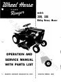
! Riding Rotary Mower
•
•
•
•
•
•
•
•
•
•
•
WITH PARTS LIST
m
WHEEL-HORSE PRODUCTS, INC.
•
•
•
•
•
•
•
•
•
•
•
•
•
•
•
•
•
•
•
•
•
•
•
•
•
•
•
•
•
•
•
•
•
•
•
•
•
o
.c
SERVICE MANUAL !
se
or
H
el
he
yW
OPERATION AND
•
•
•
•
•
•
•
•
•
•
•
SOUTH BEND, IND.
A SSEMB LY
A . Remove aI I parts from box and place i n a convenient arrange
ment on a clean, level surface.
B. Insert a Woodruff key, Part No. 1008, in the keyway in each
rear axle. Assemble rear wheels on axles with nut for set screw to
the inside making sure that the wheel hub does not touch the end
of the axle housing. The wheels are held in place with set screws
which must be tightened securely and locked with the jam nuts
provided.
w
C. Slide the front wheels onto the front spindles and secure with
washers, Part No. 1278, and snap rings, Part No. 1127.
w
D. Place steering wheel on steering column shaft and secure with
the 3(6 x I % roll pin, Part No. 1227.
E. Remove screws, holding seatspring in place, and reinstall with
hitch bar in place on top of seat spring.
w
F. Attach fenders to tool box using holes that give proper location
of fender with respect to wheels.
G. Secure seat to top of seat spring with carriage bolt provided.
The seat may be attached to either of the two holes in the seat
spring depending on operator preference.
.M
H. Screw 5Yz" long pipe nipple into elbow in exhaust port in
engine and screW muffler onto nipple. Tighten securely.
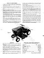
I. Attach the two 6" wheels to the mower housing using shoulder
bolt, Part No. 4177. Wheels can be moved up or down to obtain
cutting heights of Yz" to 2Yz". In the up position mower cuts a
full 3Yz" high.
yW
J. Assemble idler pulley, Part No. 1623. and shield assembly, Part
No. 4931, to mower clutch pedal. The leaf spring on the shield
assembly must be deflected down sO that it fits under the tubular
portion of the clutch pedal assembly. The idler bushing Part No.
1536 must be placed between the idler and shield. Note! The belt
must be in the idler pulley groove before these parts are a ssembled.
Remove oil filler plug. located at the left rear side of the trans
mission, and fill to level of hole with a good grade of S.A.E. 90
Gear Lube (will require about 3 pintsJ.
The transmission should be checked after every 40 hours of use.
The transmission should be drained once a year by removing plug
on bottom to drain oil. Ref, II as above paragraph. This is a
regular automotive type transmission with sliding gears and
should have the same care as your car.
B A TTE RY
The battery installed in the Model BE is a dry charged battery.
It is important that you properly prepare this battery to insure
good service and long life.
1. Remove vent caps. Remove or destroy any sealing device
which may have been used to close or restrict the vent openings.
2. Fill each cell of the battery to the proper level with the bat
tery electrolyte.
NOTE: Temperature of battery and electrolyte at time of filling
should be above 60"F. Never fill battery in the vehicle.
3. BOOST CHARGE: 15 amps. for 10 minutes or 7 amps. for 30
minutes. Adjust electrolyte level, if necessary, after charge.
4. Install battery with battery posts toward the rear of mower.
Start motor. Check to see if generator is charging properly. After
battery has been in service, add only approved water.
DO NOT ADD ACID.
TIRE S
The front tires are 3.50 x 4 pneumatic and should be filled to 2 0
pounds o f air pressure. T h e rear tires are 4.00 x 8 and should have
6 to 8 pounds of air pressure.
STARTING ENGINE
he
K. Slide mower under unit and attach the four links using the
fourth and sixth holes from the front on each side of the frame.
Use % x I bolts, Part No. 1425, spacers, Part No. 4937, washers,
Part No. 1434, and nuts, Part No. 1408, for attaching links to frame.
A light machine oil should be used on all moving parts to keep
joints from wearing and squeaking.
L. Move lift lever forward and hook lift link to pin in lift arm,
securing with washer and hair pin cotter.
2. Place gear shift lever in neutral position, lower the rotary mower
to the ground on its gage wheels, make certain that the mower
clutch is latched in the disengaged position.
3. Pull throttle lever Yz way out and turn to the right to lock it
in position. Note: The Throttle control has a locking device. Turn
the throttle control to the left to unlock, adjust to the desired
position and turn to the right to lock.
el
M. With mower clutch in disengaged. down position, slide belt
over engine pulley and place in outside groove. Release mower
clutch and check belt alignment. Tightness of belt is automatically
adjusted through the tension springs.
1. Before starting the engine open valve on sediment bowl.
(NOTE:
Auxiliary foot rest CAN NOT be used when mowing)
4. Pull choke lever all the way out to choke engine. If engine is
warm and has been running, choking will not be necessary.
H
N. Adjust position of belt stop Part No. 4930, so that it just clears
the outside of the belt when the mower is at maximum and mini
mum height and with the belt clutch engaged. This insures proper
release of mower clutch.
5. A. Model 33R has a recoil starter with an OFF and ON switch.
To start push switch to ON position and pull recoil starter.
(NOTE:
ALL
YOUR
WARRANTY
CLAIMS,
AUTHORIZED
NOTE:
WORK,
SHIPMEN1'S,
WHEEL HORSE;
MUS1'
BE
HANDLED
THROUGH
DEALER.
90 Day Warranty for Commercial Use.
BE FORE YOU START
There is NO OIL in the crankcase of the engine when shipped from
the factory. Read Engine Manual and follow all instructions per
taining to type of lubrication specified. The engine is the heart of
your Lawn Ranger and it is very important that you keep it in good
condition.
Before mowing, the moWer should be operated at a slow speed
to check all moving parts for any damage or looseness caused
in transporting.
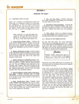
Lubricate all grease fittings with a regular pressure gun lubricant
every eight to ten hours of operation. Refer to Figure I for the
location of grease fittings.
7. Depress clutch pedal on left side of the Lawn Ranger before
selecting desired gear ra nge.
8. When starting the Lawn Ranger in winter it is desirable to de·
press clutch so starter does not have to turn transmission.
CLUTCHING
om
.c
The engine and battery carry a separate warranty by the
manufacturer. FOR ENGINE OR BATTERY SERVICE, CONTACT
YOUR LOCAL ENGINE OR BATTERY SERVICE HEADQUARTERS.
6. When engine starts push choke in to off position and regulate
throttle control by turning to the left to unlock and push in or out
to desired speed.
se
WE warrant WHEEL HORSE PRODUCTS for ONE YEAR from
date of purchase against defective parts and workmanship. We
will replace, free of charge, any defective part if returned to
the factory PREPAID". Wheel Horse Products, Inc., reserves the
right to make changes or improvements upon its products with
out imposing any obligations upon itself to install the same
upon its products that have been previously manufactured.
Keep feet clear of mower while pulling recoil starter.)
B. Model 33E has an OFF and ON key. also a starter button.
Turn key to ON position and push starter button.
or
W A RR AN T Y
There is no need to force the gear shift lever if the gears do not
immediately mesh. Depress clutch pedal all the way down and
let up, then depress again and shift. To avoid sudden starts,
release clutch pedal slowly. While in motion do not shift gears
without depressing clutch pedal.
The clutch pedal also operates the brakes WHEN DEPRESSED
ALL THE WAY DOWN. For this reason, you should depress the
clutch pedal ONLY % OF THE WAY DOWN WHEN SHIFTING
while in motion.
This clutch-brake pedal combination makes
clutching automatic as you apply the brakes to stop.
PARKING B RA KE
The parking brake is located on the left side of the Lawn Ranger
as shown in Figure I. To set the parking brake depress the clutch
brake pedal as far as possible and push the parking brake for
ward. To release the brake depress the clutch-brake pedal and
pull the parking brake back.
C ARE OF THE LAWN RA NGER
1. Keep the Lawn Ranger greased and oiled regularly. Refer to
to Figure I for the location of grease fittings. Check transmission
and engine case oil levels.
2. Keep engine air cleaner clean.
3. Keep tires properly inflated.
This will add to engine life.
See previous instructions.
4. Keep the Lawn Ranger covered and in a dry place when not
in use ..
w
5. Keep grass and dirt out of engine cowling as these will stop
the flow of air and decrease engine life.
w
6. BRAKE ADJUSTMENT. The brake band, located on the left side
of the transmission, bra kes the transmission and in turn stops the
wheels. Adjust the nut on the bra ke rod so that, when you depress
the clutch pedal all the way down. the band tightens around the
brake drum. just as the idler pulley releases the belt. Keep brake
band and drum free from oil and dirt.
w
7. Clutch.Brake Pedal Ad'justment. The clutch-brake pedal rod
may be turned in or out to adjust the pedal to operator's desired
position. Remove pin from rod and turn rod in or out for adjustment.
.M
S. When blades become dull, remove and regrind. CAUTION:
Sharpen evenly on both sides so blade does not become out of
balance.
9. On the Model BE ,check battery after every 40 hours of use.
If the mower has been in storage it may be necessary to recharge.
10. Your Lawn Ranger is only as good as the service you give it.
See your Wheel Horse Dealer for a thorough check-up after each
season of use.
6. Never leave motor running unattended.
in use - children could get hurt.
heavy grass or weeds. The sideplates may be reinstalled in an in
verted position, as shown by the dotted illustration, thus acting as
an additional foot guard. EXTREME CAUTION should be exercised
when the sideplates are removed, because of the danger of flying
debris.
9. Exercise special care when mowing around objects to prevent
the blades from striking them, and never deliberately mOw over
any object.
10. Stop operation when another person approaches - prohibit
others from riding with you on your riding mower.
1 1. Riding mowers can be tipped to either back or side. Exercise
extreme ca ution when mowing on slopes or inclines. Engage clutch
slowly and smoothly. Never abuse your mower by improper handling.
12. Never adjust mower or tractor until engine has been turned off.
13. If your Lawn Ranger is to be used for purposes other than
mowing, latch mOWer clutch in disengaged position, stop engine
and remove mower drive belt from engine pulley. The spring wire
belt stop may be deflected to remove belt. Never allow children
to operate unless you have removed this belt to prevent their
accidentally engaging mower.
(NOTE: Auxiliary Foot Rest for use only when mower Is removed.
This foot rest CAN NOT be used when mowing.)
:--'PAIIKI�IG BRAKE
O PERATI ON
WHEEL HORSE LAWN RA NGER SPECIFIC A TIONS
With proper care and adjustment. your new Wheel Horse Lawn
Ranger has been designed to give. many years of satisfactory
performance.
Preparation for operation and operating hints listed below are
recommended for all mowers and approved by the Outdoor Power
Institute for safe operation of your mower.
1. Before starting operation, clear the entire lawn area of all
debris that could catch on to or be thrown by the blades.
2. When you mow on rough terrain or in high grass or weeds. the
blade should be set at the highest cutting point. In tall grass or
weeds. a second cutting may be made to bring the grass down to
the d esired height.
3. Mowers do not operate as well in wet grass. Wet grass has a
tendency to build up on mower housing and give non-uniform dis
charge.
(SPECIfICATIONS SUBJlfCT T O CHANGIf WITHOUT NOTICIf!
4. Fill gas tank outdoors. Avoid spilling gasoline and don't fill the
tank while engine is running or while you are smoking.
om
.c
"'--'
se
or
H
el
Figure 1
Remove key when not
7. Don't overspeed the engine. Excessive cutting speed or tamper·
ing with the governor can 'be dangerous.
S. The �ower has side plates which may be removed when cutting
he
yW
1 1. When replacing belts be sure to purchase them from your
Wheel Horse Dealer, as these belts are specifically designed for
each application. (NOTE: Make sure all pulleys are in line.)
5. While mowing. give undivided attention to the job at hand, keep
the cutting path in area of operation' clear of all persons, particu
larly small childreno
,. .... . . . . . .. . . . . . . . . . . . 54 inches
41X inches
Width Overall (with mower) . . ...... .
o. 33)1 inches
Width Overall (without mower)
',
26% inches
Width at Front Wheels,
24% inches
Height
33)1 inches
Height to Top of Hood
28% inches
Net Weight (33E)
"
365 Ibs.
Nef Weight (33R) . . . ..
339 Ibs.
Frame Clearance . .
10% inches
6 HoP.
Engine (4 cycle, single cylinder, air cooled) . . . .... . .. .
Fuel Capacity
,
4 quarts
Tires (front) ............ ..... .. .3.50 x 4 Pneumatic (10" wheel d'a.)
Tires (rear) ....... ... ..... .
4 .00 x 8 Pneumatic (16" wheel dia.)
Length Overall
Wheelbase
.
.
.
.
.
. .
.
.
.
.
.
.
.
.
.
.
.
.
.
•
•
•
•
•
•
•
•
•
•
•
,
0 •
0
•
•
•
• •
• •
'
•
.
. .
.
.
.
.
.
.
.
.
.
0
0
•
.
.
.
. 0 0
•
•
•
0 0
•
•
•
•
•
•
0
0
•
•
•
•
•
•
•
•
•
.
0
•
.
0
0
.
0
0 0 0 0 0 •
•
0 •
• 0
•
•
• 0
•
•
•
•
•
•
•
0
•
•
•
•
• 0
•
•
•
•
•
•
•
0 0
0
•
• •
•
• •
• •
• •
•
•
•
•
•
•
•
•
•
•
•
•
•
•
•
•
•
•
• 0
•
•
•
•
•
•
•
•
•
• 0
• 0 0
•
•
•
•
•
•
•
•
•
•
•
•
•
•
•
•
• •
•
•
•
•
•
•
0
•
•
•
•
•
•
•
• •
•
• 0
•
•
•
•
•
•
•
•
•
•
0
•
•
•
•
•
•
•
•
0
• 0
•
•
•
•
0
0 0
• 0
• • 0
•
•
• 0
0
•
•
•
•
•
•
•
•
0 0
•
•
•
•
•
• 0
0
•
•
•
•
•
•
•
•
•
•
•
•
•
• 0
•
•
•
•
•
•
•
•
•
•
•
•
•
•
•
•
•
•
0
0
•
•
•
•
.
•
•
•
•
.
•
•
•
•
•
•
•
•
•
0 •
•
•
•
• 0
• •
0
• • •
0
•
•
• 0
•
•
•
•
•
, 0
•
•
•
•
• •
•
•
•
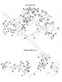
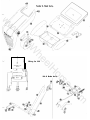
Main
Frame Ass'y.
.M
w
w
w
•
Wheel Ass'y.
m
o
.c
se
or
&
H
el
he
yW
Steermg
/ I
\
w
/
1'1/
Ii
I
//-�
�
.M
w
w
Wiring
for
33E
Lift &
or
H
el
T"ECUMS£H e H.P.
ENGINE
he
yW
1
Brake
Ass'y.
m
o
.c
se
w
yW
.M
w
w
(D
I
he
Transmission
el
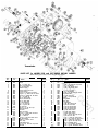
PARTS LIST for MODELS 33R and 33E RIDING ROTARY MOWER
Ref.
No.
Part
No.
1232
1372
1239
1242
1244
1262
1434
1273
1277
4912
1287
1303
1
1
5
3
1
2
2
6
5
1
1
3
2
3
1
1
1
1
1
2
3
1
1
1
2
4
1
2
2
1
1
2
35
36
37
38
39
40
41
42
43
44
45
46
47
48
49
50
51
52
53
54
55
56
57
58
59
60
61
62
63
64
65
Part
No.
1329
1331
1339
1340
1345
1346
1349
1350
1363
1364
1384
1385
1483
4944
4930
4452
1406
1316
1408
1410
1413
1416
1417
1418
1423
1424
1425
1426
1427
1428
1480
1430
1432
Name
Qu ant ity
�6-18 x 3X Hex Hd. Cap Screw
�6 Shakeproof Washer
%-16 x 3X Hex Hd. Cap Screw
X x lX Roll Pin
X-20 x 'K6 Thumb Screw
X-20 x 17\', Thumb Screw
X x X x lX Key
Ya x 1X Roll Pin
%-16 x % Hex Hd. Cap Screw
�6 Round Nut
% Std. Pipe Plug
X -20 x !1 Keps Screw
Decal
Plug-Wheel
Belt Stop
Gasket-Tank
X-20 Hex Nylock Nut
�6-18 Hex lock Nut
%-16 Hex Nylack Nut
!1-13 Hex Nylock Nut
%-24 Hex Nylock Nut
X Split lock Washer
�6 Split lock Washer
% Split lock Wa.her
%-16 x % Hex Hd. Cop Screw
!1.13 Hex Jam Nut
%.16 x 1 Hex Hd. Cap Screw
%-16 x 1X x Hex Hd. Cap Screw
%-16 x 2 Hex Hd. Cop Screw
X-20 x % Hex Hd. Cap Screw
#8 x % Tapping Screw
X-13 x lX Carriage Hd. Bolt
�,-24 x !1 Rd. Hd. Mach. Screw
4
2
1
5
2
1
.1
1
1
2
1
4
1
2
1
om
.c
23
24
25
26
27
28
29
30
31
32
33
34
Handle Grip
Knob
Ya x 1 Cotter Key
No. 15 Woodruff Key
X Std. Pipe Plug
Ten.ion Spring
Square Head Set Screw
Grea.e Fitting
%·16 x 2 Hex Hd. Cap Screw
�6·18 x �6 Socket Hd. Set Screw
X·20 x X Socket Hd. Set Screw
X x 1!1 Rotl Pin
% 1.0. Shaft Cotlar
No. 9 Woodruff Key
% 1.0. Snap Riltg
1 1.0. Snap Ring
�6 x 1!1 Roll Pin
7\'6 x 1!1 Roll Pin
Ya Pipe Nip
%.16 x lX Sq. Hd. Cup
Point Set Screw
Oil Seal
Hoi r Pi n Cotter
X·20 x % Dog Point Set Screw
�1 x 'K6 Roll Pin
Ya x 1 Roll Pin
X -20 x % Rd. Hd. Mach. Screw
% SAE Washer
10-32 x % Mach. Screw
Wire Clip
Tube & Nut Au'y.
!1-13 x 2% Hex Hd. Cap Screw
Oil Seal
Ref.
No.
se
1000
1001
1002
1008
1013
1014
1023
1030
1032
1042
1066
1081
1085
1122
1127
1128
1136
1135
1192
1206
Quantity
or
1
2
3
4
5
7
8
9
10
12
13
14
15
16
17
18
19
20
21
22
Name
H
When ordering parts alway. list Part No. and name of part.
1
4
4
21
1
1
4
2
4
8
3
2
6
1
6
15
1
2
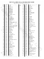
PARTS LIST for MODELS 33R and 33E RIDING ROTARY MOWER
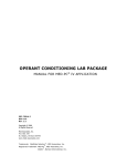
When ordering parts always list Part No. and name of part.
���-.-�-. . ��- .
Ref.
N0'
1
Part
No.
��-
. ������- .. ��-....
Name
....
��
.�--.�..
Ref.
+--
-�-
._-
No.
-····
Part
+--
No.
--�···--�-
I-
Name
Quantity
--�--
. _--
.
--.
-...---+...
-.-�
2
141
3917
Bevel Pinion
3918
Steeting Pivot
1
3919
Steering Arm
2
1
Needle Bearing
2
71
1516
Bushing
1
142
143
72
1518
Needle Bearing
1
144
2297
Brace
73
74
75
1528
1529
Needle Bearing
2
Needle Bearing
2
Needle Bearing
1
1240
3935
3940
U·Bolt
1530
1531
145
147
149
Needle Bearing
1
150
Tool Box
1532
Needle Bearing
151
Ball Bearing
152
3945
Upper Steering Shaft
1
79
1533
1536
1
2
3587
3944
Idler Bushing
1
3949
Clevis Pin
81
82
1576
1611
"V" Belt 70" A Section
2
1
1621
1623
Engine Pulley
1
Idler Pulley
1
3950
3973
3978
3979
Idler Arm
Pulley
1
1
154
155
1664
Rear Wheel Ass'y.
3586
3080
Front Wheel Ass'y.
2
2
1739
Tecumseh Muflle r
3585
4910
Upper Plunger Rod
1745
1751
Ammeter
Reverse Idler Gear
w
1508
83
84
85
87
88
90
91
93
.M
w
w
77
78
Starter Button
156
157
158
159
160
"xhaust
Brake Rod
Drag Link
Lower
1
Steering
Shaft
1
Seat
Seat Cushion
1
1
Pivot Brake
1
Fender R.H.
1
Fender l. H.
1
1
1
1
161
1
1
164
4915
4204
165
4206
Battery Clamp
1
166
167
4211
Spacer
4213
�
Shift Stick
163
1
1
1
1
Belt Guard
1
1
1
Gas Cop
1754
�" Std. Pipe Nipple
95
96
1786
1787
Fuel Strainer
Straight Fitting
1
1
168
4440
97
99
1796
Fuel Line
1
169
4216
2638
2639
Tecumseh
1
1
170
4217
171
4218
4220
).{
Front Axle
1
1
1
4222
Quadrant
1
174
175
4907
4232
lift
Throttle
1
1
176
4233
Choke
1
177
4235
Differential Pinion Gear
4
lower Plunger Ass'y.
1
1
Tank
1
1
182
4905
4438
4407
4249
lift Lever
1
178
180
181
183
1861
3279
Tecumseh
5 � " Lg.
6 hp. Engine (Electric)
6 hp. Engine (Recoil)
Rod Control Stud
Off.On Switch
(33R)
Shift Fork
1
1
2
103
104
105
3515
Front Shift Roil
106
3516
Rear Shift Rail
107
108
3517
3518
Boll Stop
110
111
3522
Input Gear
3523
Hi and 2nd Gear
112
113
3524
3525
Low and Reverse Gear
Cluster Gear
1
1
114
3526
Splined Pinion
1
3503
3514
Shift Collar
172
173
he
101
102
yW
3998
94
100
1
el
Spring Stop
1
1
2
1
Bottom
4405
Fuel Tank Ass'y.
4901
Front Spindle
1
2
4410
Wheel Horse Decal
2
4412
80ttom Steering Support
4413
Steering
1
1
1
186
187
117
3537
Seat Spring
118
119
3573
1143
� .20
1
1
1
190
120·
3577
3578
Boot
2
1
191
Plunger Guide
1
192
3605
3624
Tie Rod
1
Compression Spring
1
193
194
3653
Battery
188
189
3656
3680
Switch
(33E)
Plunger Cap
1
196
197
3900
Transmission Case R.H.
1
199
195
Sector
4414
Steering Wheel
4415
4416
Hood
4417
4418
Brake Set Lever
1
1
Shift Decal
1
4419
Shield
1466
Retainer
1
2
1539
4422
Bushing
1
Instrument Decal
4429
Clutch Rod
1
1
Lawson Engine Base
1
1
om
125
126
127
1
1
.c
se
or
H
184
185
Reduction Gear
123
124
Std.
1 ).{ Std. Pipe Nipple
x
1
1
1
Reduction Pinion
Button Head Screw
�
Pipe Cap
900
1
3527
%
Std. Pipe Elbow
1
Fuel Tank
3528
x
1
3 Std. Pipe Nipple
4406
115
Shift Pin Stop
).{
x
Hole Plug
116
121
122
V
-.--
69
76
.."-.-/
'-����..
Quantity
�.�+.--- -- -�- -t---- -� . ..
Bushing
1504
68
...
....
128
3901
Transmission Case L.H.
1
200
3902
4430
Clutch Pedal
129
Brake Drum
1
4431
Ground Switch to Coil Wire
130
3903
Brake Shaft Gear
4432
Starter Switch to Starter Wire
131
3904
Axle
1
2
201
202
1
203
Ballery to Starter Wire
132
3905
Differential
2
204
4433
4434
133
3906
Bull Gear
1
208
1227
134
3907
Spline Shaft
1
'f6
1
1
209
3930
Hood Stand Channel Strut
Case
Generator to Ammeter Wire
x
1% Roll Pin
1
1
1
2
135
3908
Axle Gear
2
215
4900
Frame Ass'y.
1
136
3909
Differential Pin
5
4904
Hitch
1
137
138
139
3910
3912
Clu ster
1
217
218
4427
Hood Stand Channel Ass'y.
1
Gasket
1
219
1755
Street EI
4437
Brake Band Ass'y.
1
220
1756
�" lock Nut
1
1
140
3915
Locating Pin
2
. _L._..__. . .._ ... -!-_.�.
Shaft
90· �" Std.
..
..
w
yW
.M
w
w
he
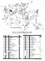
Lawn Ranger Rotary Mower
When
_.
Quantity
35
36
37
38
39
40
41
42
43
44
45
46
47
48
49
50
51
52
53
54
55
56
57
58
59
60
61
62
63
64
65
66
67
Part
No.
3130
1185
1194
1122
1613
1042
1426
3141
1304
3757
1587
1418
1408
1343
4935
4934
1423
4940
4939
4938
1017
1002
4936
1425
4937
4914
1434
3725
1391
4121
4177
1484
3710
Name
Quantity
Gear - Foce
2
Wo.her - Lock %
2
Key - Woodruff #5
2
Key - Woodruff #9 Pulley
1
Pulley 3X Dia.
1
Set ;'6-18 x ;'6
Screw
1
Bolt
Hex %·16 x lY.t
6
Cover
Geor
2
Screw - Hex Hd. #8
32 x 14Self Top. 8
Plug - Button
2
Belt 43" A Section
1
Wosher - Lock %
4
Nylock %.16
Nuts
12
Nut % x 18
2
Bracket
L.H.
1
Bracket
R.H.
1
Bolts %-16 x %
4
Link - Front
2
Link - Rear
2
Rod - Front (Link Pivot)
1
Washer X SAE Plain
5
Pin - Cotter Va x 1
5
Rod - Rear (Link Pivot)
1
Bolt %.16 x 1
4
Spacer
4
Lift
Bar
1
Washer % SAE Plain
4
Cover - End Plote
2
10
Screw - Rd. Hd. Mach. 14·20 x % (SEMS)
Wheel - 6" Dia.
2
Stud - Shoulder
2
DecoI (Caution)
2
Deco!
2
om
.c
Deck
1
Clutch Latch
1
Clutch Pedal
1
Shield
1
Twin Housing & Bearings
1
Housing
1
Bearing
4
Oil Seal
2
Spindle
2
Cup
2
Pin - Roll 14x %
4
Blade
Rotory - R.H.
1
1
Blade - Rotary - L.H.
Washer - Dome
2
Screw - Hex - Nylock % - 16 x % 2
4
Race - Bearing Thrust
2
Bearing - Thrust
Key #5
2
Gear Spur
2
Snap Ring
2
Fitting
2
Grease
Hex. H. Cap Screw ;'6 x 18.%
4
Hex. Hd. Nut Nylock ;'6 x 18
4
As.'y. Housing - Cron Shaft
2
Housing
1
Bearing
1
Pulley Idler
Bushing
Idler
Bolt
Hex %.16 x % CP
Bolt 142- 0 x 1
CP
1
1
Nut - Nylock 14·20
Washer - 14 SAE CP
1
Spring - Clutch
2
Shoft
1
Ref.
No.
Part.
se
4917
4924
4927
4931
4151
3726
1508
1303
3724
3716
1382
3718
3719
1336
1398
1535
1534
1194
3131
1127
1030
1443
1407
4150
3138
1515
1623
1536
1363
1439
1406
1436
1486
3715
Name
Name of
or
1
2
3
4
5
6
7
8
9
10
11
12
13
14
15
16
17
18
19
20
21
22
23
24
25
26
27
28
29
30
31
32
33
34
Part
No.
Ordering Parts Always List Part Number and
H
Ref.
No.
el
PARTS LIST FOR LAWN RANGER ROTARY MOWER
8 -16-62
Form No. 135