1
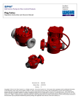
Excellent
Oil & Gas
Solutions
Emergency Back Pressure Relief Valve
Operating and Maintenance Instructions
SAFETY INFORMATION
! WARNING
IMPORTANT SAFETY INFORMATION ENCLOSED. READ THIS OPERATING AND MAINTENANCE
INSTRUCTIONS MANUAL BEFORE OPERATING PRODUCT.
IT IS THE RESPONSIBILITY OF THE EMPLOYER TO PLACE THE INFORMATION IN THIS MANUAL
INTO THE HANDS OF THE OPERATOR. FAILURE TO READ, UNDERSTAND AND FOLLOW THE
OPERATING AND MAINTENANCE INSTRUCTIONS MANUAL COULD RESULT IN SEVERE
PERSONAL INJURY OR DEATH.
Contents
Product Description....................................................3
Pressure/Temperature Ratings.....................................3
End Connections........................................................ 3
Description of Operation.............................................3
Installation................................................................. 3
Maintenance..............................................................4
Service........................................................................5
Disassembly..............................................................5
Replacement and Assembly.......................................8
Setting and Adjusting Pressure....................................8
Vessel Test Procedures.................................................9
Trouble Shooting Guide............................................12
Parts and Seals Kit Listing...........................................13
Drawing of 3” Valve - 15,000 NSCWP.........................14
Drawing of 3” 20K Valve - 20,000 NSCWP...................15
Drawing of 4” Valve - 602/1002.................................16
Drawing of 4” Valve - 1502 MxF - 15,000 NSCWP........17
Drawing of 4” 10K Safety Iron Valve - 10,000 NSCWP..18
Drawing of 4” 15K Big Iron Valve - 15,000 NSCWP......19
2
I. Product Description:
III. End Connections:
Weir SPM's Emergency Back Pressure Relief Valve provides
over-pressure protection for reciprocating pumps, treating
lines, pressure vessels, and other equipment operating
under high-pressure, high-flow conditions. Compact and
simple to operate, the valve is direct acting, relying on the
system's hydraulic pressure to overcome a preset nitrogen
gas force to relieve. It is externally adjustable from zero
pressure to maximum setting.
Weir SPM's 3" or 4" Emergency Back Pressure Relief Valve is
available with Weir SPM Wing Union or Safety Iron™
Connections. The nameplate will indicate the cold working
pressure allowable for each assembly.
Wing union connections on the relief valve are
interchangeable with other union connections of
the same size and figure (pressure rating). Caution
must be taken to avoid mixing different ratings of
wing connections. There are various sizes and
figures that are capable of making marginal
connections. Safety Iron™ connections are
universal requiring no male or female as the wing
union does. Failure to observe good judgement
may lead to failure of components and danger to
life and limb. Always verify working pressure
ratings of each connection before use.
Unlike Shear Relief Valves, which use common nails to
trigger the release, the Weir SPM valve will reseat once the
system pressure reduces. And unlike many "High-Lift"
Valves, which require a substantial drop in pressure before
they will reseat, the Weir SPM valve exhibits little blow
down and will reseat at or near the "cracking pressure".
Manufactured to Weir SPM's stringent Quality Assurance
System, all pressure bearing components are made from
high quality material. The forged body features an integral
wing union male inlet or Safety Iron™ type connections,
suitable for the pressure rating of the component.
This device is intended to discharge to atmospheric
pressure when it relieves. It should not be subjected to any
significant backpressure. The choice of discharge
connections is offered as a convenience for the user and
does not imply high-pressure capability.
The low-pressure outlet is available with an integral wing
union female or Safety Iron™ connection. Conforming to
conditions of design and performance in API RP520, the
Weir SPM Emergency Back Pressure Relief Valve is intended
for liquid service. It is not intended for elevated
temperatures nor as a safety device in case of fire.
Observe all instructions, cautions and warnings as
noted in this brochure. Failure to do so can lead to
equipment damage, personal injury or loss of life.
! WARNING: NEVER BLOCK DISCHARGE PORT!
Available in 3" or 4", this valve offers pressure ranges from
1,000 - 20,000 psi. The valve is best suited for over
pressure protection in a "slick water" medium. However,
due to its large bore, it should work well in drilling mud
applications also.
IV. Description of Operation
The back pressure relief valve operation is a simple balance
between the nitrogen (or suitable gas) acting on the piston
and the inlet liquid pressure acting on the rod and wear
sleeve. The equation is Pressure times Area equals
Force (PxA=F). The ratio of areas is approximately:
25.0:1 for the 15,000 psi rated valve
This means that nitrogen pressure of 100 psi can counter an
inlet line pressure of 2500 psi for the 15,000 psi rated
Emergency Back Pressure Relief Valve. Variations in this
ratio in practice are due to friction of seals and will be
discussed in section VIII. Setting and Adjusting
Pressure.
II. Pressure/Temperature
Ratings:
The Weir SPM 3" or 4" Emergency Back Pressure Relief Valve
is available in the following configurations at this time.
Fluid Side Ratings:
INLET
(LOW PRESS)
DISCHARGE
PRESSURE INT. END
RANGE NSCWP
(PSI)
(PSI) SERVICE
SEALS
TEMP.
RANGE
3" - 1502M
3" - 1502F 1000 - 15000 15000 Standard -30°C - 110C
3" - 2002M
3" - 2002M 1000 - 20000 20000 Standard -30°C - 110C
4" - 1002M
4" - 1002M 1000 - 10000 10000 Standard -30°C - 110C
4" - 1502M
4" - 1502M 1000 - 15000 15000 Standard -30°C - 110C
Gas Side Specifications:
Low Pressure Working Range:
Recommended Nitrogen Bottle:
Recommended Rupture Disc:
V. Installation:
The Weir SPM Emergency Back Pressure Relief Valve should
be installed in a branch on the high-pressure pump line
(Fig. 1). To avoid stability problems, the valve should not
be mounted directly at the pump discharge, but rather
somewhat removed from the pump due to the fluctuating
discharge signature of the pump. Preferably, the valve
should be mounted in the vertical position as shown, to
reduce the tendency for contaminants and particulates in
the fluid to collect at the throat of the main seal. However,
any position is acceptable within approximately 30 degree
declination (angle from vertical).
0 to 800 psi
2,000 psi
2,250 psi
Bottle or source gas pressure should be twice maximum
low pressure working range.
Operating Temperature:
-22°F to 120°F
(-30°C to 49°C)
3
The gas regulator and gas back pressure relief valve should
be installed as close to the relief valve as possible. The
nitrogen filled high-pressure cylinder must be secured to
either a skid or trailer or by staking it to the ground.
ALWAYS REMEMBER
Any type of liquid may be unloaded through the valve. The
valve will tolerate clean liquids better than others. And
lighter liquids will flow greater rates than heavier liquids.
Particulates, abrasives and contaminants will not preclude
the valve from opening at the appropriate set pressure.
However, abrasive materials will cause some wear between
the wear sleeve, nozzle, and main seal. While these
components feature wear resistant surfaces, their life will be
reduced as the abrasives increase in the fluid.
1. ! WARNING: DISASSEMBLY UNDER PRESSURE CAN
CAUSE SERIOUS INJURY OR DEATH.
2. Always use a new parts kit for reassembly.
3. Clean all components thoroughly prior to reassembly
using protective clothing and safety glasses.
4. Check sealing surface area of valve gate and nozzle for
pitting, erosion or other flaws. Failure in sealing can
result if these areas are not smooth.
5. Use only Weir SPM relief valve parts on Weir SPM relief valves.
6. This device is intended to discharge to atmospheric
pressure when it relieves. It should not be subjected to
any significant back pressure.
CAUTION
It is important for the user to consider the
consequences of a valve that does not fully reseat
after it has relieved. In the event that this might
present a danger to personnel or equipment, Weir
SPM highly recommends that an isolator valve be
placed between the pressure line and the Relief
Valve.
VI. Maintenance:
General Inspection and Repair:
The Weir SPM 3" or 4" Emergency Back Pressure Relief Valve is a
well designed, dependable component that should provide long
term reliable performance for the user. Like any device,
however, it requires routine inspection and servicing to
guarantee that it is fully functional.
With the device installed, as shown in (Fig. 1), any time the
pressure exceeds the set pressure at the Emergency Back
Pressure Relief Valve, the fluid will pass through the valve
and out the discharge.
The valve is intended to be used as an emergency pressure relief
device only, and should not be subjected to continuous fluid
flow except in emergency situations. If the valve is subjected to
extended flow or abrasive fluids, the valve may not reseal
completely once the pressure is relieved. If complete fluid shutoff is desired, a shut-off valve (such as Weir SPM's plug valve)
should be installed in series with the relief valve, which can be
closed once the over-pressure is relieved.
PRESSURE REGULATOR
BACK PRESSURE REGULATOR
HIGH PRESSURE
NITROGEN CYLINDER
BACK PRESSURE
RELIEF VALVE
DISCHARGE
TO ATMOSPHERE
TO WELL
FIG. 1
Weir SPM recommends that the valve be serviced on a weekly
basis. O-rings and the mating seal surfaces can be inspected at
that time and replaced as required. There are sealing surfaces on
this device that require maintenance. For the valve to operate
properly and safely, these items must be kept in good condition.
Inspection and servicing should be conducted in accordance
with a recognized maintenance program. The more severe the
usage, the more often the maintenance.
At low flow rates, the valve will discharge fluid at
approximately the set pressure (Fig. 2). At higher flow
rates, the valve will discharge fluid at levels above the set
pressure. API 520 defines the valve flow capacity as the rate
that can be relieved at an over pressure of 25%. When the
fluid pressure falls to the set pressure level or below, the
valve will reseat and reseal.
1
1
2
3
2
3
Any time the valve is sequenced in operation as a result of
overpressure (other than routine calibration with water prior to
pumping operations), it must undergo a teardown and
comprehensive inspection. This should be done
immediately following the completion of the current
job. Not properly servicing the valve once it has discharged frac
media (including frac sand) is dangerous practice and increases
the risk of leakage during the next operation. Disassembly,
Repairs, and Reassembly should be done in accordance with
service manual instructions.
FIG. 2
Fluid pressure below set pressure-rod and valve gate seated and
reseated.
Fluid pressure slightly above set pressure-rod and valve gate slightly
off nozzle.
Fluid pressure substantially above set pressure-rod and valve gate
off nozzle.
CAUTION
Weir SPM's 3" or 4 " standard service Emergency
Back Pressure Relief Valve is not intended for use in
the sour gas environment. ! WARNING: DO NOT
USE FOR H2S SERVICE. Weir SPM does offer a
separate series of H2S service back-pressure valves.
Contact your Weir SPM representative for advice
about sour gas service applications.
4
In order to determine the N2 gas line pressure, the valve is
equipped with a corrosion resistant bourdon tube gauge with a
pressure rating of 0 to 600 psi. This range is adequate to allow
the valve to reach maximum operational working pressure, and
yet still allow precise adjustments in line pressure. However, if
the relief valve is only operated at release pressures below 6000
psi, then the pressure gauge could be replaced with a 0 - 300
psi gauge. This would increase the accuracy at which the N2 gas
line pressure could be adjusted. The primary consideration is not
to operate the pressure gauge beyond 75% of its rated capacity
for any extended period of time. If additional information is
needed, please contact the Weir SPM Engineering department.
VII. Service:
allow fluid to leak past the flange during the relieving
function. If this surface shows signs of damage, the body
should be replaced.
TOOLS REQUIRED
1. Vise
2. 1/2" Hex Socket Wrench & 1/4" Hex Socket Wrench
3. Screwdriver
4. 2 lb. Hammer
5. Special Torque Tool (see Fig. 6)
6. Ø 1/2" BAR x 12" LG (Aluminum or Brass)
7. 600 Grit Sandpaper
8. Anti-seize Lubrication
9. Hand and Eye Protection
10. (2) 1/2 - 13 UNC x 1 1/2 LG bolt (for cylinder
extraction)
2.) Cylinder: 5
Visually inspect the inside surface of the cylinder for wear or
damage. Damage to this surface renders this component
unusable and should be replaced.
3.) Piston: 8
Visually inspect the piston seal areas for damage or wear. If
damage or wear is evident, the part should be replaced.
4.) Flange: 1
Inspect the seal 26 pocket in the nylon sleeve at the
bottom. Inspect seal 19 and 25 pockets for wear. The
sleeve and seal pockets should be in good condition. If not
the flange should be replaced.
DISASSEMBLY: (Fig. 3 & 4)
! WARNING: MAKE SURE THAT THERE IS NO PRESSURE
ON THE VALVE
5.) Spider: 11
Visually inspect the fluid discharge areas for erosion and
corrosion. Some wear in these areas is expected. Any
damage in these areas that extends deeper than .06"
renders the parts unusable and they should be replaced.
1. If the nitrogen cylinder is attached, close the highpressure cylinder valve 2 . Then bleed down and
remove the nitrogen line 14 from the back-pressure
valve 1 (Fig. 3).
2. Secure the valve in a horizontal position by clamping the
valve body 3 in a vise (Fig. 4).
3. Remove the eight lower and ten upper 5/8" socket
screws 30 from the flange 1 . Separate the cylinder 5
from the flange 1 . If piston extraction is difficult after
jackscrews are fully extended replace with 1/2 -13 UNC x
1 1/2 LG or longer bolts for easier disassembly. Separate
the flange 1 from the body 3 by using jackscrews.
Remove the entire bonnet assembly from the body.
4. Remove the cotter pin 13 from the clevis pin 29 .
Remove the clevis pin 29 from the cylinder rod 4 . The
valve gate 23 , wave spring 14 , spring retainer 9 ,
and bushing 10 can now be removed from the cylinder
rod 4 . Remove the piston 8 with the cylinder rod
from the flange assembly 1 .
5. Hold the cylinder rod 4 by the flat at its mid length.
Exercise care not to damage the rod’s other surfaces.
Remove the hex jam nut 22 and washer 33 from the
cylinder rod 4 . The bumper 32 can now be removed.
Remove the jam nut 22 . Then the piston 8 and
sleeve 21 can be removed.
6. Remove the spider 11 from the valve body 3 . Remove
the nozzle 6 along with the seat 12 from the body.
7. Gently remove the seal 28 from the valve body 3 .
6.) Valve Gate 23 and Nozzle 6 :
The gate and nozzle are considered expendable items and
spares should be kept on hand at all times. The life of these
parts is dependent on the type and length of service to
which they are exposed.
Visually inspect the gate and nozzle for indications of wear
and of pitting, erosion or corrosion damage. These are
critical components in the function of the valve. Any
indications of deterioration more than .01" deep should be
cause to replace these items. Deterioration of the sealing
surfaces less than .01" deep should be removed by
polishing with 600 grit sandpaper. Keep flatness of surface
when polishing. Total depth of polishing should not be
more than .015" for each sealing surface. Look for
contaminants that, while not damaging to the gate and
nozzle, will keep the parts from sealing. Remove any
foreign material found.
7.) All Seals: 15 19 24 25 26 27 28
All elastomer seals should be replaced regardless of
condition.
See drawing 2L23886 (page 13)
for Seal and Part Kits.
Inspecting Components: (Fig. 4)
1.) Body: 3
Visually inspect the o-ring groove area beneath the nozzle
6 . This is a critical area. If the groove shows indications
of damage from erosion or corrosion, the body should be
replaced. It is not repairable.
See all assembly drawings for
3” and 4” configuration for
parts and seal part numbers
(pages 14 through 19).
Visually inspect the fluid discharge surface for erosion or
corrosion. Some wear in this area is expected. Any damage
to this surface that extends deeper than .10" renders the
part unusable and it should be replaced.
Visually inspect nylon guide bushing on flange assy 1 seal
surface for erosion or corrosion. Damage to this area will
5
FIG. 3
6
S
T
A
N
D
A
R
D
U
N
I
O
N
H
A
M
M
E
R
I
R
O
N
S
A
F
E
T
Y
2A25568
2A26134
2A28064
2A28078
2A28079
2A28082
BUNA
BUNA
BUNA
VITON
3"-15K
4"-15K
4"-10K
4"-6K
3"-20K
P26327
'B'
SEAL
SIZE
'C'
300
600
P26239
'A'
2A26329
BUNA
3"-15K
600
600
300
300
600
600
300
600
P26239
P26239
P26327
P26327
P26239
P26239
P26327
P26239
2A23402
2A23402
1A23493LT
BUNA
3"-15K
PART NO.
2A24348
2A26463
BUNA
3"-20K
2A24348V
2A26133
2A27829
2A28005
BUNA
2A27828
2A28137
2A28006
2A27232LT
BUNA
BUNA
SHOWING SAFETY IRON
CONFIGURATION
4"-10K
4"-15K
DETAIL "A"
SCALE = 1:2
'D'
14.31
14.31
16.38
16.38
14.31
14.31
16.38
14.25
14.25
'E'
29.21
29.21
31.25
31.25
29.21
29.21
31.25
29.21
29.21
29.21
OPERATING
PRESSURE
1,000-10,000
1,000-15,000
1,000-20,000
1,000-20,000
1,000-6,000
1,000-10,000
1,000-15,000
1,000-15,000
1,000-10,000
1,000-15,000
'E'
'D'
13
1
14
PART NO
.XXX
.XX
fractional
125
surface roughnes sall
machinedsurfaces
.010 unlessotherwise noted
linear
tol
+ 1/32
+ .01
+ .005
+ 30'
Angular tol
All diameters concentric to
DIMENSIONS ARE IN INCHES
UNLESS OTHERWISE NOTED
1
ITEM QTY
1
P104469
P101847
P23417
P23364
P23362
P23354
P23355
'B'
P23356
P23353
P23359
P23358
P23160
'A'
14 1
13 1
12 1
11 1
10 1
9
1
8
1
7
1
6
1
5
1
4
1
3
1
2 REF
9
12
4
(7.00)
6
3
SCALE = 1:4
CYLINDER DETAIL
7
(33.00)
2
DESCRIPTION
VALVE ASSY
HOSE ASSY - 120.00 LG. w/1/4" SAE37° SWIVEL ENDS
90° ADAPTER - SM XPM/04X04
TEE - SM x SMx PM/04x04x04
CONNECTOR - SM x PF/04 x 04
COUPLING - SF x SF/04 x 04
BACK PRESSURE REGULATOR - 10000 PSI /5-800 PSI RANGE
REGULATOR - 6000 PSI /0-800 PSI RANGE
GAUGE PSI, Ø 2 1/2",1/4" NPT
GAUGE 4000 PSI, Ø2", 1/4" NPT
NIPPLE - 1/4" NPT x 3.00 LG.
CYLINDER NIPPLE - 1/4" NPT
CYLINDER NUT
HIGH PRESSURE CYLINDER (CHARGED TO 2500PSI)
8
5
10
Material:
Description:
HALF
12/14/00
Approved:
Drawnby:
BACK PRESSURE
BCW
JAS
1L23577
DrawingNo:
EMERGENCY RELIEF VALVE FULL BORE
INSTALLATION DETAIL
Date:
Scale:
DO NOT SCALE DRAWING
7601 WYATT DRIVE
FT WORTH TEXAS 76108-2587
11
1-1/4"-8 UN JAM NUT
22
FLAT WASHER
33
27
SEAL
CYLINDER
5
32 BUMPER
8 PISTON
24 SEAL
25 SEAL
SLEEVE
21
FLANGE ASSEMBLY
SEAL
19
SEAL
SPIDER
30 5/8" - 11UNC SHCS
1
4
CYLINDER ROD
15
26
SEAL RING
11
FLOW OUT
(LOW PRESSURE)
VALVE BODY
3
SEE DETAIL B
WING NUT
2
FLOW IN
BUSHING
10
13 .125 x .75 COTTER PIN
(HIGH PRESSURE)
.31 x 3.00 CLEVIS PIN
WAVE SPRING
14
29
SPRING RETAINER
9
6 NOZZLE
VALVE GATE
23
DETAIL B
28 SEAL
FIG. 4
7
REPLACEMENT AND ASSEMBLY
1. Screw the pressure regulator 8 adjustment screw all the
way out (Counter Clockwise) to open.
- See ALWAYS REMEMBER Section before
assembly.
- The reassembly of the valve is in approximate reverse
order to the disassembly process. Ref (Fig. 4).
- Lightly lubricate all surfaces prior to assembly.
CAUTION
When the handle hits its stop, the top of the
regulator may start to unscrew. Do not unscrew
the regulator top any further. ! WARNING:
FAILURE TO COMPLY MAY CAUSE INJURY TO
PERSONNEL WHEN PRESSURE IS APPLIED TO THE
VALVE.
1. Install seal 28 into valve body. Replace nozzle 6 and fit
over seal 28 . CAUTION: If seal 28 is difficult to seat,
push into place with seat and tap lightly. Remove seat to
ensure seal is properly seated. Install the spider 11 into
the valve body 3 and fit to the nozzle 6 .
2. Secure the cylinder rod 4 in a vertical position using the
flats at its mid length.
3. Install the sleeve 21 and the piston 8 with seals 27
and 24 onto cylinder rod 4 . Secure the piston 8
with jam nut 22 using blue Loctite. Install bumper 32 ,
washer 33 and hex jam nut 22 using blue Loctite.
4. Install seals 25 , 26 and 19 into the flange
assembly 1 . Uniformly apply a small amount of anti
-seize compound on the inside friction surface of the
nylon bushing of the flange assembly 1 . Carefully
insert the cylinder rod 4 with piston 8 into the flange
assembly 1 .
5. Insert wave spring 14 into spring retainer 9 followed
by new or polished valve gate 23 . Install the
bushing 10 into spring retainer 9 . Assemble the
spring retainer 9 and the cylinder rod 4 together by
using the clevis pin 29 . Secure the clevis pin 29 by
cotter pin 13 .
6. Install the entire cylinder rod-flange package into the
valve body 3 . Tighten the eight 5/8" socket screws 30
that hold the flange assembly 1 to the body 3 using
proper torque orientation to 110 ft-lb (lubricated).
7. Install cylinder 5 onto flange 1 and tighten the ten
5/8" socket screws 30 using proper torque orientation
to 110 ft-lb (lubricated).
8. Tighten the connector 13 (See Fig. 3) into the
cylinder 5 with thread sealing compound.
9. Using shop air, connector 13 (See Fig. 3), and vent
hole on the valve assembly 1 , stroke the piston 8 in
and out to assure that it moves freely.
10. The valve is now ready for pressure testing as discussed
in Section VIII, Pressure Testing.
2. Open the valve 15 on the nitrogen bottle or from the
air source. The inlet gauge 6 on the regulator 8
should indicate the pressure in the nitrogen bottle.
3. Tighten the backpressure regulator 9 adjustment screw
fully (Clockwise).
4. Turn the adjustment screw on the regulator 8 until the
gas line pressure reaches a nominal set point. Use the
chart in Figure 5 to find gas pressure versus "set”
pressure.
NOTE
Always set the pressure in the Rising Direction. If
you pass a set point drop the pressure to about 50
psi below the set point and re-approach the set
point.
5. Test the working pressure by slowly raising the line
(liquid) pressure until the valve begins to relieve. The
treating line pressure should stabilize and stop rising
once this happens.
Reduce the line pressure until the valve gate 23 is fully
seated on the nozzle 6 (See Fig. 4).
7.
The relationship between gas pressure and line (liquid)
pressure is defined by Figure 5. These values are from
actual tests and should be accurate. However, if the
predicted gas pressure does not produce the desired
set pressure, you may have to adjust the regulator 8
up or down.
Some of the factors affecting performance include
temperature, and gas used (air vs nitrogen).
Observe all instructions, cautions and
warnings as noted in this manual. Failure to
do so can lead to equipment damage,
personal injury or loss of life.
VIII. Setting and Adjusting
Pressure:
The Emergency Back Pressure Relief Valve is direct acting.
The pressure set on the nitrogen regulator is directly related
to the relief pressure. The higher the nitrogen pressure, the
higher the relief set point. Use the following procedure to
obtain the correct set point. A few attempts at working
pressure may be required to confirm the set point (Fig. 3).
Clean dry air at a minimum of 1350 psi (6000 psi max) may
also be used.
CAUTION
Bleed off all air from the fluid system. Trapped air
will become energized and may cause injury to
personnel when the valve relieves.
6.
8.
Reset the nitrogen pressure to the new set point. Test
the line again until the valve relieves.
9.
With pressure on the back pressure relief valve, back
the adjustment screw of the backpressure regulator 9
(Fig. 3) out (Counter Clockwise) until the backpressure
regulator exhausts gas.
10. Then slowly turn the adjustment screw in (Clockwise)
until the backpressure regulator 9 just stops
exhausting gas.
8
NOTE
Once the relief valve is adjusted to the correct set
point it is normal for the gas pressure to rise as
fluid in the discharge line (to well) (Fig. 1)
approaches the set pressure. The backpressure
regulator, will vent gas to compensate this increase
in gas pressure.
VIII. Setting and Adjusting
Pressure (continued) :
IX. Vessel Test Procedures:
Prior to shipment, product testing procedure 4S12497
requires that each emergency valve pass a one time vessel
test at 150% it's rated working pressure. Then, when
conducting subsequent vessel tests on used or re-certified
valves, limit the pressure to 100% of rated working pressure
as required by 4S12497.
NOTE: This chart does not apply to the 3"
2002/20K ERV valve. Contact Weir SPM
Engineering for 3" 2002/20K Full Bore Emergency
Unloading Valve Performance Data Values.
Line
Set Pressure
(PSI)
350
500
1000
1500
2000
2500
3000
3500
4000
4500
5000
5500
6000
6500
7000
7500
8000
8500
9000
9500
10000
10500
11000
11500
12000
12500
13000
13500
14000
14500
15000
Emergency relief valves should always be vessel tested in
accordance with product testing procedure 4S12497.
! WARNING: A FULLY ASSEMBLED RELIEF VALVE
SHOULD NEVER BE PRESSURE TESTED WITH THE
OUTLET DISCHARGE PORT BLANKED OR BLOCKED
OFF AS THIS WILL RESULT IN A CATASTROPHIC
FAILURE. Below is excerpt from 4S12497 regarding the
proper vessel testing procedure on used or recertified
emergency relief valves:
Required
Nitrogen (or
gas) Pressure
(PSI)
0
14
28
41
55
69
83
97
110
124
138
152
166
179
193
207
221
234
248
262
276
290
303
317
331
345
359
372
386
400
414
Vessel Test Procedure for Used or Recertified Emergency
Back Pressure Relief Valves
1. Assemble valve body with required blanking seat,
spider, and dummy blanking cap for testing purposes
only. (See Fig. 7 & 8 "Vessel Test Procedure" for
seat, spider, and cap part numbers)
2. Attach valve to testing pump.
3. Fill with water and bleed-off all air from the system
prior to testing.
4. Hydrostatically test by pressuring to 100% of
product's designed working pressure.
5. Hold pressure for the duration to time specified in
4S12497 and check for leaks. Assembly is considered
acceptable if there are no visual indications of leaks,
and the pressure drop is within the allowable range
specified in 4S12497, section 6.0 relief valve.
6. Reduce pressure to zero.
Recommendation: Purchase a spare spider designated for
the sole purpose in testing relief ERV valves as to prevent
damage to the "original spider" that was assembled in your
N2 relief valve.
FIG. 5
9
WRENCH EXTENSION
KEEP TORQUE WRENCH AND
WRENCH EXTENSION "IN-LINE"
VALVE BONNET
VALVE FLANGE
1/2” ALLEN WRENCH
3/8” - 16 HHCS
WRENCH EXTENSION (2P24505)
APPROXIMATE CENTER OF GRIP
1/2" DRIVE TORQUE WRENCH (10 - 100 ft. lbs.)
(P24509)
15/16" SOCKET 1/2" DRIVE 6 POINT
SOCKET SCREWS
(15.00)
11.75
26.75
1. USE ABOVE TO TO TORQUE AND REMOVE SOCKET SCREWS
HOLDING VALVE FLANGE TO VALVE BODY AND VALVE BONNET.
VALVE BODY
2. BE CERTAIN TO USE AN APPROPRIATE TORQUE WRENCH THAT FITS THE
DIMENSIONS AND FEATURES OF THE ABOVE ILLUSTRATION. (WEIR SPM CAN FURNISH
ITS P24509 TORQUE WRENCH.)
3. SET THE TORQUE WRENCH TO 62 FT-LBS. THIS WILL DEVELOP A 110 FT-LB
TORQUE AT THE SOCKET SCREW.
4. KEEP THE TORQUE WRENCH AND EXTENSION "IN-LINE" AT ALL TIMES.
FIG. 6
10
VESSEL TEST PROCEDURE FOR
3" AND 4" N2 EMERGENCY RELIEF VALVES
3" & 4" EMERGENCY RELIEF VALVE
! WARNING:
INCORRECT
TESTING
PROCEDURE
BULL PLUG
OUTLET PORT
INLET PORT
PUMP
GAUGE PLUG
FLOW
FIGURE 7. EXAMPLE OF IMPROPER TESTING
SET UP OF EMERGENCY RELIEF VALVE
NEVER BLANK OFF OUTLET PORT
BLANKING SEAT
PART NO. 2P27370
CORRECT
TESTING
PROCEDURE
BLANKING CAP
PART NO. 2P27582
3" & 4" E.R.V. BODY
O-RING
OUTLET PORT
INLET PORT
PUMP
GAUGE PLUG
FLOW
FIGURE 8. EXAMPLE OF PROPER TESTING
SET UP OF EMERGENCY RELIEF VALVE
VERIFY THAT OUTLET PORT IS OPEN
FIG. 7
and
FIG. 8
11
TROUBLESHOOTING GUIDE
Always follow existing company procedure concerning identifying equipment for inspection, and removing equipment from
service. The following is intended as a general guide in helping resolve most problems encountered in repairing relief
valves. If problems are not covered here please contact Weir SPM for assistance at (817) 246-2461.
SYMPTOM
1. Rapid erosion
PROBLEM
SOLUTION
a) Used as continuous bypass
a) Use only as an emergency back pressure relief
device
b) Install sufficient quantity of valves to meet capacity
requirements
b) Used beyond rated capacity
2. Shuddering (Rapid
opening and closing)
a) System pressure hovering at set pressure
b) Back pressure relief valve located too close to
pump's discharge
c) Valve installed before pressure dampener
a) Raise set pressure slightly
b) Relocate relief valve. Refer to service literature
for information on proper location.
c) Relocate relief valve behind pressure dampener
3. Loss of pressure (Valve
does not seal or loses
fluid through discharge)
a) Valve not set properly
b) Damaged nozzle or valve gate
c) Damaged high pressure cylinder connection
d) Contaminants trapped between valve gate
and nozzle
a) Set valve correctly.
b) Replace damaged parts
c) Replace damaged parts
d) Clean affected parts
4. Valve leaks through
weephole or between
valve body and cap
a) Damaged inner or outer or both flange seals
a) Replace damaged seals
5. Valve releases higher or
lower than intended relief
pressure
a) Valve set incorrectly
a) Reset valve to desired pressure per instructions in
Section VIII
12
Parts and Seal Kit Listing
3” Emergency Relief Valve - Back Pressure - Full Bore
6
8
7
5
14
2
1
10
11
13
DETAIL" A
SCALE = 1:1
9
FLOW
OUT
12
15
16
4
SEE DETAIL A
16
15
14
13
12
11
10
9
8
7
6
5
4
3
2
1
1
1
1
1
1
1
1
1
1
1
1
1
1
1
1
1
ITEM
QTY
"R"
"Q"
"P"
"N"
"M"
"L"
"K"
"J"
"H"
"G"
"F"
"E"
"D"
"C"
"B"
"A"
SEAL RING
CYLINDER ROD SEAL
PISTON SEAL - OUTER
FLANGE SEAL - UPPER
FLANGE SEAL - LOWER
WAVE SPRING
SEAL
PISTON SEAL - INNER
COTTER PIN
CLEVIS PIN
BUSHING
SPRING RETAINER
SPIDER
SEAT
NOZZLE
VALVE GATE
DESCRIPTION
PART NO
UNLESS OTHER WISE NOTED
DIMENSIONS ARE IN INCHES
DO NOT SCALE DRAWING
7601 WYATT DRIVE
FT WORTH TEXAS 76108 - 2587
+
- 1/32
+ .01
+ .005
+ 30'
Angulartol
All diameters concentric to
Scale:
fractional
linear
tol
Date:
.XX
.XXX
VALVE SECTION
.010 unless otherwise noted
VALVE SHOWN IN THE
CLOSED POSITION
125
Drawnby:
JAS
Approved:
VK
PARTS&SEALSKITLISTING
3” & 4” EMERGENCY RELIEF VALVE
BACK PRESSURE - FULL BORE
Material:
surface roughness all
machined surfaces
NONE
1/22/99
Description:
DrawingNo:
MATERIAL
2L23886
SEALS KIT
APPLICABLE ASSY's
J
K
M
N
P
Q
R
4L23550
BACK PRESSURE
P23334
P23335
P16637
P23304
P23303
P23333
4P10258
4L23634
BACK PRESSURE - VITON
P23334
P19296
P10063
P23304
P23303
P24152
4P13259
P23334
P23334
P16637
P23304
P23303
P23333
4P22394
P23334
P26577
P10063
P23304
P23303
P24152
4P22395
C
D
E
3P23298LT
3P23877
PART NO.
2A27694
2A27695
3" 20K BACK PRESS
3" 20K BACK PRESS - VIT
PARTS KIT
PART NO.
4L23548
APPLICABLE ASSY's
BACK PRESSURE
A
B
3P23880
3P24314
3P23876
G
H
J
K
L
M
N
P
Q
R
4P23875
P23881
P23878
P23334
P23335
P23879
P16637
P23304
P23303
P23333
4P10258
F
4L23632
BACK PRESSURE - VITON
3P23880
3P24314
3P23876
3P23298LT
3P23877
4P23875
P23881
P23878
P23334
P19296
P23879
P10063
P23304
P23303
P24152
4P13259
4L24315
BACK PRESSURE
3P23880
3P24314
3P23876
3P24263
3P23877
4P23875
P23881
P23878
P23334
P23335
P23879
P16637
P23304
P23303
P23333
4P10258
3P23876
3P24263
3P23877
4P23875
P23881
P23878
P23334
P19296
P23879
P10063
P23304
P23303
P24152
4P13259
4L24316
BACK PRESSURE - VITON
3P23880
3P24314
2A27692
3" 20K BACK PRESS
3P24349
2A26892
3P24263
3P23877
4P23875
P23881
P23878
P23334
P28229
P23879
P16637
P23304
P23303
P23333
4P22394
2A27693
3" 20K BACK PRESS - VIT
3P24349
2A26892
3P24263
3P23877
4P23875
P23881
P23878
P23334
P28229
P23879
P10063
P23304
P23303
P24152
4P22395
2A28338
4" 10K BACK PRESS
3P23880
3P24314
3P24263
3P23877
4P23875
P23881
P23878
P23334
P28201
P23879
P16637
P23304
P23303
P23333
4P10275
3P23880
3P24314
3P24263
3P23877
4P23875
P23881
P23878
P23334
P28201
P23879
P16637
P23304
P23303
P23333
4P22397
3P23880
3P24314
3P24263
3P23877
4P23875
P23881
P23878
P23334
P28201
P23879
P10063
P23304
P23303
P24152
4P22398
2A28339
2A28340
4" 15K BACK PRESS
4" 10K - 15K BACK PRESS - VIT
METAL SEALS KIT
PART NO.
4L28048
APPLICABLE ASSY's
BACK PRESSURE
4L28049
BACK PRESSURE - VITON
4L28050
BACK PRESSURE
4L28051
A
B
3P23880
3P23874
3P23880
3P23880
3P23874
3P24314
3P23880
3P24314
2A28052
3" 20K BACK PRESS
3P24349
2A26892
2A28053
3" 20K BACK PRESS - VIT
3P24349
2A26892
BACK PRESSURE - VITON
13
20
11
14
16
26
17
2
19
21
18
27
3
1
1
22
SECTION
A-A
23
33
31
14
7
30 3
29
10
25
R12
24
8
32
SEE DETAIL B
4
5
28
9
6
DETAIL B
36
35
15
13
20 37
SEE SERVICE LITERATURE
FOR TEST PROCEDURES
WARNING
A
A
34
INSTALLUSING BLUE LOCTITE.
125
surface roughness all
machined surfaces
.010 unless otherwise noted
.XX
fractional
+ 1/32
+ .01
+ .005
.XXX
+ 30'
Angular tol
All diameters concentric to
linear
tol
DIMENSIONS ARE IN INCHES
UNLESS OTHERWISE NOTED
ITEM QTY
NAME PLATE (4P18295) TO BEAR:
a) ASSY P/N
b) MFG.DATE
c) SERIAL NO.
d) PRESSURE RANGE
WARNING LABEL
1/8" NPTPOP-OFF RELIEF VALVE
1/2"~13 NC SHSS x 3/4" LG. (S.S.)
1/2"~13 NC SHSS x 5/8" LG. (S.S.)
1 1/4" FLAT WASHER
BUMPER
EYE BOLT
5/8-11 UNC SHCS x 1.75 LGLT
.31 x 3.00 CLEVIS PIN
SEAL
SEAL
SEAL
SEAL
SEAL
VALVE GATE
1 1/4 - 8UN HEX JAM NUT PLAIN
SLEEVE
DRIVE SCREW
SEAL
1/4 - 18 NPT HP PIPE PLUG
RETAINER RING
NAME PLATE
SEAL RING
WAVE SPRING
.125 x .75 COTTER PIN
SEAT
SPIDER
BUSHING
SPRING RETAINER
PISTON
RETAINER SEGMENT - PSL
NOZZLE ASSEMBLY
CYLINDER
CYLINDER ROD
VALVE BODY
3 FIG 1502 WING NUT-PSL
FLANGE ASSY
DESCRIPTION
4.
Material:
Description:
3:8
12/12/00
BACKPRESSURE-15000NSCWP
FULL BORE VALVE ASSEMBLY
3"EMERGENCY RELIEF VALVE
Date:
Scale:
MDM
VK
2A23402
DrawingNo:
Approved:
Drawnby:
DO NOT SCALE DRAWING
7601 WYATT DRIVE
FT WORTH TEXAS 76108-2587
2P27625
P24707
P19967
P24708
P24752
3P24754
P25003
P23863
P23881
P28201
P23334
P23333
P23304
P23303
3P23880
P23299
3P23404
P18055
P16637
P10453
P10261
4P18295
4P10258
P23879
P23878
3P23876
3P24263
4P23875
3P23877
3P23292
3P10260-III
3P24314
2P28045
2P23884
2P27228
2P10257-III
2A27232LT
PART NO
TORQUE BOLTS TO 110 FT-LBS
37 1
36 1
35 2
34 2
33 1
32 1
31 1
30 18
29 1
28 1
27 1
26 1
25 1
24 1
23 1
22 2
21 1
20 4
19 1
18 1
17 1
16 1
15 1
14 1
13 1
12 1
11 1
10 1
9
1
8
1
7
3
6
1
5
1
4
1
3
1
2
1
1
1
3
2. PRESSURE RANGE: 0 - 15,000PSI
1
NOTES:
Full Bore Valve Assembly
3” Emergency Relief Valve - Back Pressure - 15,000 NSCWP
15
B
2A24348V
2A24348
ASSY NO.
BUNA
APPLICATION
P/N 'A'
4P22394
22
8
26
7
P/N 'B'
P16637
P/N 'C'
P23333
P24152
10
24
23
34
29 5
6
28
4
5
P10063
1
35
21
4P22395
SCALE = .38:1
SECTION "A-A"
VITON
2
16
3
19
15
11
25
18
1
20
17
26
30
P/N 'D'
P28229
P28229
14
19
36
13
12
9
32
33
SCALE = 1:1
DETAIL "B"
SEE SERVICE LITERATURE
FOR TEST PROCEDURES
WARNING
A
A
31
INSTALL USING BLUE LOCTITE.
125
surface roughness all
machined surfaces
.010 unless otherwisenoted
.XX
fractional
+ 1/32
+ .01
+ .005
.XXX
+ 30'
Angular tol
All diameters concentric to
linear
tol
DIMENSIONSAREININCHES
1 1/4 - 8UN HEX JAM NUT - PLAIN
SLEEVE
DRIVE SCREW
SEAL
1/4 - 18 NPT HP PIPE PLUG
RETAINER RING
NAME PLATE
SEAL RING
WAVE SPRING
.125 x .75 COTTER PIN
SPIDER
BUSHING
SPRING RETAINER
PISTON
RETAINER SEGMENT
NOZZLE ASSY
CYLINDER
CYLINDER ROD
VALVE BODY
WING NUT 3" 2002
FLANGE ASSY
DESCRIPTION
1/2"~13NC SHSS x 3/4" LG. S.S.)
1/2"~13NC SHSS x 5/8" LG.(S.S.)
EYEBOLT
5/8 - 11 UNC SHCS x 1.75LGLT
.31 x 3.00 CLEVIS PIN
SEAL
SEAL
SEAL
SEAL
SEAL
VALVE GATE
WARNING LABEL
11/4" FLAT WASHER
BUMPER
1/8" NPT POP-OFF RELIEF VALVE
Material:
Description:
.375
2/24/03
Approved:
Drawnby:
JED
BCW
2L27700
DrawingNo:
FULL BORE VALVE ASSY LISTING
3" 20K RELIEF VALVE
20,000 NSCWP
Date:
Scale:
DO NOT SCALE DRAWING
7601 WYATT DRIVE
FT WORTH TEXAS 76108-2587
2P27625
P24752
3P24754
P24707
P19967
P24708
P25003
P23863
P23881
P101241
'D'
'C'
P23304
P23303
3P24349
P23299
3P23404
P18055
'B'
P10453
P12439
4P18295
'A'
P23879
P23878
3P24263
4P23875
3P23877
3P23292
3P16929
2A26892
2P28045
2P23884
2P27238
2P19422
2A27232LT
PART NO
UNLESSOTHERWISENOTED
ITEM QTY
36 1
35 1
34 1
33 1
32 2
31 2
30 1
29 18
28 1
27 1
26 2
25 1
24 1
23 1
22 1
21 1
20 1
19 4
18 1
17 1
16 1
15 1
14 1
13 1
12 1
11 1
10 1
1
9
8
1
7
3
6
1
5
1
4
1
3
1
2
1
1
1
TORQUE BOLTS TO 110 FT-LBS.
5
PRESSURE RANGE
ALTERNATE VALVE BODY: 2P24346
SERIAL NO.
d)
4
MFG. DATE
c)
ASSY P/N
b)
a)
3. NAME PLATE (4P18295) TO BEAR:
2. PRESSURE RANGE: 0-20,000 PSI
1
NOTES:
Full Bore Valve Assembly Listing
3” 20K Relief Valve - 20,000 NSCWP
16
2A26133
ASSY NO.
4"-602
SIZE
3
22
2A26134
16
26
1
1
4"-1002
2
17
20
11
19
21
18
27
A-A
P/N 'A'
2P27234
2P27235
SECTION
30
23
14
7
P/N 'B'
2P10276
29
20 37
10
25
24
3
8
32
SEE DETAIL B
4
5
2P10963
33
31
13
15
35
36
DETAIL B
28
9
6
SEE SERVICE LITERATURE
FOR TEST PROCEDURES
WARNING
A
A
34
INSTALL USING BLUE LOCTITE.
.XX
fractional
125
surface roughness all
machined surfaces
.010 unless otherwise noted
linear
tol
+ 1/32
+ .01
+ .005
.XXX
+ 30'
Angular tol
All diameters concentric to
DIMENSIONS ARE ININCHES
UNLESS OTHERWISE NOTED
ITEM QTY
WARNING LABEL
1/8" NPT POP-OFF RELIEF VALVE
1/2"~13 NC SHSS x 3/4" LG. (S.S.)
1/2"~13 NC SHSS x 5/8" LG. (S.S.)
11/4" FLAT WASHER
BUMPER
EYEBOLT
5/8-11 UNC SHCS x 1.75 LGLT
.31x3.00 CLEVIS PIN
SEAL
SEAL
SEAL
SEAL
SEAL
VALVE GATE
11/4-8 UN HEX JAM NUT PLAIN
SLEEVE
DRIVE SCREW
SEAL 2-346
1/4 - 18 NPT HP PIPE PLUG
RETAINER RING
NAME PLATE
SEAL RING
WAVE SPRING
.125x.75 COTTER PIN
SEAT
SPIDER
BUSHING
SPRING RETAINER
PISTON
RETAINER SEGMENT
NOZZLE ASSEMBLY
CYLINDER
CYLINDER ROD
VALVE BODY
WING NUT
FLANGE ASSY
DESCRIPTION
4.
NAME PLATE (4P18295) TO BEAR:
a) ASSY P/N
b) MFG. DATE
c) SERIAL NO.
d) PRESSURE RANGE
Material:
Description:
3:8
11/01/05
Approved:
Drawnby:
MATERIAL
TJN
MDM
2L26002
DrawingNo:
FULL BORE VALVE ASSEMBLY LISTING
4" 602/1002 EMERGENCY RELIEF VALVE
BACK PRESSURE
Date:
Scale:
DO NOT SCALE DRAWING
7601 WYATT DRIVE
FT WORTH TEXAS 76108-2587
2P27625
P24707
P19967
P24708
P24752
3P24754
P25003
P23863
P23881
P28201
P23334
P23333
P23304
P23303
3P23880
P23299
3P23404
P18055
P16637
P10453
P10278
4P18295
4P10275
P23879
P23878
3P23876
3P24263
4P23875
3P23877
3P23292
3P10277
3P24314
2P28045
2P23884
'A'
'B'
2A27232LT
PART NO
TORQUE BOLTS TO 110 FT-LBS
37 1
36 1
35 2
34 2
33 1
32 1
31 1
30 18
29 1
28 1
27 1
26 1
25 1
24 1
23 1
22 2
21 1
20 4
19 1
18 1
17 1
16 1
15 1
14 1
13 1
12 1
11 1
10 1
9
1
8
1
7
3
6
1
5
1
4
1
3
1
2
1
1
1
3
2. PRESSURE RANGE: 0-15,000 PSI
1
NOTES:
Full Bore Valve Assembly Listing
4” 602/1002 Emergency Relief Valve - Back Pressure
INSTALL USING BLUE LOCTITE.
4
MFG. DATE
SERIAL NO.
PRESSURERANGE
b)
c)
d)
17
16
19
15
11
25
18
1
20
17
7
26
TORQUE BOLTS TO 110 FT-LBS.
ASSY P/N
a)
3. NAME PLATE (4P18295) TO BEAR:
2. PRESSURE RANGE: 0-15,000 PSI
1
NOTES:
SECTION "A-A"
B
35
21
30
1
(10.50)
3
4
5
29
4
8
2
24
23
34
(10.50)
14
19 36
32
33
SEE SERVICE LITERATURE
FOR TEST PROCEDURES
WARNING
A
A
31
4
.XXX
.XX
fractional
125
surfaceroughnessall
machinedsurfaces
.010unlessotherwisenoted
linear
tol
+ 1/32
+ .01
+ .005
+ 30'
Angulartol
Alldiametersconcentricto
DIMENSIONSAREININCHES
1/2"~ 13NC SHSSx5/8"LG.(S.S.)
EYE BOLT
5/8-11UNC SHCSx1.75LGLT
.31x3.00 CLEVIS PIN
SEAL
SEAL
SEAL
SEAL
SEAL
VALVE GATE
11/4-8UNHEXJAMNUT-PLAIN
SLEEVE
DRIVE SCREW
SEAL
1/4-18 NPTHP PIPE PLUG
RETAINE RRING
NAME PLATE
SEAL RING
WAVE SPRING
.125x.75 COTTERPIN
SPIDER
BUSHING
SPRING RETAINER
PISTON
RETAINER SEGMENT
NOZZLE
CYLINDER
CYLINDER ROD
VALVE BODY
WING NUT 4"1502
FLANGE ASSY
DESCRIPTION
1/8"NPT POP-OFF RELIEF VALVE
1/2"~ 13NC SHSSx3/4"LG.(S.S.)
WARNING LABEL
11/4" FLAT WASHER
BUMPER
DETAIL“B"
9
27
13
12
Material:
Description:
.63:1
11/8/05
Approved:
Drawn by:
JED
MDM
MATERIAL
2A25568
DrawingNo:
FULL BORE-BACK PRESSURE
4" 1502 MxF EMERGENCY RELIEF VALVE
15000NSCWP
Date:
Scale:
DO NOT SCALE DRAWING
7601 WYATT DRIVE
FT WORTH TEXAS 76108-2587
2P27625
P24752
3P24754
P24707
P19967
P24708
P25003
P23863
P23881
P28201
P23334
P23333
P23304
P23303
3P23880
P23299
3P23404
P18055
P16637
P10453
P12439
4P18295
4P22397
P23879
P23878
3P24263
4P23875
3P23877
3P23292
3P16929
3P24314
2P28045
2P23884
2P27239
2P11729
2A27232LT
PART NO
6
UNLESSOTHERWISENOTED
ITEM QTY
36 1
35 1
34 1
33 1
32 2
31 2
30 1
29 18
28 1
27 1
26 1
25 1
24 1
23 1
22 1
21 1
20 1
19 4
18 1
17 1
16 1
15 1
14 1
13 1
12 1
11 1
10 1
1
9
1
8
3
7
1
6
1
5
1
4
1
3
1
2
1
1
22
28
10
Full Bore - Back Pressure
4” 1502 M x F Emergency Relief Valve - 15,000 NSCWP
MFG. DATE
SERIAL NO.
PRESSURE RANGE
b)
c)
d)
INSTALL USING BLUE LOCTITE.
ASSY P/N
a)
18
2
12
15
1
9
21
14
16
13
1
22
2
NAME PLATE (4P18295) TO BEAR:
3. PRESSURERANGE: 0 - 10,000PSI
2
1
NOTES:
3
4
25
DETAIL“B”
(8.38)
28
26
TORQUE BOLTS TO 110 FT-LBS.
SECTION "A-A"
17
4
4
20
19
6
27
(8.38)
15 32
30
31
SEE SERVICE LITERATURE
FOR TEST PROCEDURES
WARNING
A
29
1
1
1
1
1
1
1
1
1
1
1
1
1
12
11
10
9
8
7
6
5
4
3
2
1
PART NO
125
surface roughness all
machined surfaces
.010 unless otherwise noted
fractional
+ 1/32
linear
+ .01
.XX
tol
+ .005
.XXX
+ 30'
Angular tol
All diameters concentric to
DIMENSIONS ARE IN INCHES
DESCRIPTION
FLANGE ASSY
VALVE BODY
CYLINDER ROD
CYLINDER
NOZZLE ASSEMBLY
PISTON
SPRING RETAINER
BUSHING
SPIDER
.125x.75 COTTER PIN
WAVE SPRING
1/4"~18 NPT HP PIPE PLUG
NAME PLATE
SEAL2-346
DRIVE SCREW
11/4"~8UN HEX JAMNUT PLAIN
SLEEVE
VALVE GATE
SEAL
SEAL
SEAL
SEAL
SEAL
.31x3.00 CLEVIS PIN
EYE BOLT
5/8"~11UNCSHCSx1.75LGLT
BUMPER
11/4" FLAT WASHER
1/2"~13 NCSHSSx5/8"LG.(S.S.)
1/2"~13 NCSHSSx3/4"LG.(S.S.)
WARNING LABEL
1/8" NPT POP-OFF RELIEF VALVE
7
23
4-10K SAFETY IRON CLAMP KIT ASSEMBLY
DETAIL “B"
8 10
5
Material:
Description:
.63:1
9-12-08
MATERIAL
BACK PRESSURE - 10000 NSCWP
Approved:
Drawn by:
BCW
SJE
2A27828
DrawingNo:
FULL BORE VALVE ASSEMBLY
4" 10K SAFETY IRON EMERGENCY RELIEF VALVE
Date:
Scale:
7601 WYATT DRIVE
FT WORTH TEXAS 76108-2587
DO NOT SCALE DRAWING
2A27232LT
2P27237
2P23884
2P28045
3P24314
3P23292
3P23877
4P23875
3P24263
P23878
P23879
4P18295
P10453
P16637
P18055
3P23404
P23299
3P23880
P23303
P23304
P23333
P23334
P28201
P23881
P23863
P25003
3P24754
P24752
P24708
P24707
P19967
2P27625
2A25927
11
UNLESS OTHER WISE NOTED
ITEM QTY
1
4
13
15
14
1
16
1
22
2
1
23
17
1
24
1
18
25
18
1
26
1
1
27
19
1
28
1
2
29
20
2
30
1
1
31
21
1
32
33 REF
18
24
Full Bore Valve Assembly
4” 10K Safety Iron Emergency Relief Valve - Back Pressure - 10,000 NSCWP
INSTALL USING BLUE LOCTITE.
PRESSURE RANGE
d)
19
15
12
9
21
14
1
16
SERIAL NO.
c)
13
MFG. DATE
b)
22
ASSY P/N
a)
(Ø4.00)
4
B
31
17
26
1
(10.50)
3
4
2
25
TORQUE BOLTS TO 110 FT-LBS.
SECTION "A-A"
3. NAME PLATE (4P18295) TO BEAR:
2. PRESSURE RANGE: 0-15,000 PSI
1
NOTES:
4
5
30
20
19
(Ø4.00)
(10.50)
15 32
28
29
A
SEE SERVICE LITERATURE
FOR TEST PROCEDURES
WARNING
A
27
+ 1/32
+ .01
+ .005
+
Angulartol
- 30'
Alldiametersconcentricto
125
surface roughness all
machined surfaces
.010unlessotherwisenoted
.XXX
.XX
fractional
DIMENSIONSAREININCHES
linear
tol
5
5/8-11 UNC SHCS x1.75LGLT
.31 x 3.00 CLEVIS PIN
SEAL
SEAL
SEAL
SEAL
SEAL
VALVE GATE
1 1/4-8 UN HEX JAM NUT - PLAIN
SLEEVE
DRIVE SCREW
SEAL
1/4-18 NPT HP PIPE PLUG
NAME PLATE
WAVE SPRING
.125 x.75 COTTER PIN
SPIDER
BUSHING
SPRING RETAINER
PISTON
NOZZLE
CYLINDER
CYLINDER ROD
VALVE BODY
FLANGE ASSY
DESCRIPTION
1/2"~13 NC SHSS x3/4"LG.(S.S.)
1/2"~13 NC SHSS x5/8"LG.(S.S.)
EYE BOLT
1 1/4" FLAT WASHER
BUMPER
1/8" NPT POP-OFF RELIEF VALVE
4-15K SAFETY IRON CLAMP KIT ASSEMBLY
WARNING LABEL
DETAIL "B"
23
11
10
7
Material:
Description:
5:8
10/10/08
Approved:
Drawnby:
MATERIAL
15000 NSCWP
SJE
BCW
2A28137
DrawingNo:
FULL BORE - BACKPRESSURE
4" 15K SAFETY BIG IRON EMERGENCY RELIEF VALVE
Date:
Scale:
DO NOT SCALE DRAWING
7601 WYATT DRIVE
FT WORTH TEXAS 76108-2587
2A25402
2P27625
P24752
3P24754
P24707
P19967
P24708
P25003
P23863
P23881
P28201
P23334
P23333
P23304
P23303
3P23880
P23299
3P23404
P18055
P16637
P10453
4P18295
P23879
P23878
3P24263
4P23875
3P23877
3P23292
3P24314
2P28045
2P23884
2P27240
2A27232LT
PART NO
UNLESSOTHERWISENOTED
ITEM QTY
33 REF
32 1
31 1
30 1
29 1
28 2
27 2
26 1
25 18
24 1
23 1
22 1
21 1
20 1
19 1
18 1
17 2
16 1
15 4
14 1
13 1
12 1
11 1
10 1
9
1
8
1
7
1
6
1
5
1
4
1
3
1
2
1
1
1
18
24
8
Full Bore - Back Pressure
4” 15K Safety Big Iron Emergency Relief Valve - 15,000 NSCWP
SAFETY INFORMATION
! WARNING
IMPORTANT SAFETY INFORMATION ENCLOSED. READ THIS OPERATING AND MAINTENANCE
INSTRUCTIONS MANUAL BEFORE OPERATING PRODUCT.
IT IS THE RESPONSIBILITY OF THE EMPLOYER TO PLACE THE INFORMATION IN THIS MANUAL
INTO THE HANDS OF THE OPERATOR. FAILURE TO READ, UNDERSTAND AND FOLLOW THE
OPERATING AND MAINTENANCE INSTRUCTIONS MANUAL COULD RESULT IN SEVERE
PERSONAL INJURY OR DEATH.
Weir SPM
7601 Wyatt Drive
Fort Worth
TX 76108
USA
© 2009 Weir SPM
Tel: (817) 246 2461
Fax (817) 246 6324
www.weiroilandgas.com
V.1 01/09