1
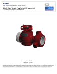
SPM®
Well Service Pumps & Flow Control Products
Plug Valves
Operation Instruction and Service Manual
Document P/N:
Release Date:
Revision:
2P36784
6/30/2014
B
Copyright © 2014, S.P.M. Flow Control, Inc.. All rights reserved. S.P.M. Flow Control, Inc. is the owner of the copyright and all confidential information
in this document, which must not be copied in whole or in part, in any form or by any means, and the information in it must not be used for any
purpose other than the specific purpose for which it has been provided without the prior written consent of the copyright owner. SPM, SAFETY IRON,
SAFETY HAMMER, SUR-DROP, DESTINY, STAMPEDE, VERIBAND, DURALAST and GLADIATOR are trademarks and/or registered trademarks of S.P.M. Flow
Control, Inc.. WEIR is a trademark and/or registered trademark of Weir Engineering Services Limited. Certain features of some of the products disclosed in
this document may be protected worldwide by patents pending and registered in the name of S.P.M. Flow Control, Inc..
Document P/N:
Release Date:
Revision:
2P36784
6/30/2014
B
THE FOLLOWING ICONS DENOTE IMPORTANT INFORMATION WITHIN THIS MANUAL.
GENERAL INFORMATION
INSTALLATION AND OPERATION
MAINTENANCE AND REPAIR
SALES AND SUPPORT
NOTE
CAUTION
WARNING/ DANGER
2
Document P/N:
Release Date:
Revision:
2P36784
6/30/2014
B
WARNING: IMPORTANT SAFETY INFORMATION ENCLOSED. READ THIS OPERATING AND
MAINTENANCE INSTRUCTIONS MANUAL BEFORE OPERATING PRODUCT.
WARNING: THIS INFORMATION MUST BE AVAILABLE TO ALL PERSONNEL THAT WILL OPERATE AND
MAINTAIN EQUIPMENT. FAILURE TO READ, UNDERSTAND AND FOLLOW THE OPERATING AND
MAINTENANCE INSTRUCTIONS MANUAL COULD RESULT IN SEVERE PERSONAL INJURY OR DEATH!
Most SPM® products generate, control or direct pressurized fluids; therefore, it is critical that those who work
with these products be thoroughly trained in their proper application and safe handling. It is also critical that
these products be used and maintained properly!!
SPM® flow products contain elastomeric seals and are not intended to provide proper functionality when
exposed to fire.
WARNING: MISUSE, SIDE LOADING, IMPROPER MAINTENANCE, OR DISASSEMBLY UNDER PRESSURE
CAN CAUSE SERIOUS INJURY OR DEATH!
The following information is given in good faith and should aid in the safe use of your SPM® products. This
information is not meant to replace existing Company's safety policies or practices. It is important to read and
understand the "General Safety Data for all SPM® Products" and the SPM® Product Safety Guide for "Union and
Union End Products". Both of these are available from Weir Oil & Gas.
Safety Guide for Plug Valves:
Personal Responsibilities:
A-1 When using these assemblies, appropriate PPE is required: safety glasses, approved safety shoes and hard
hat must be worn. Hammering and lifting these assemblies must be done with caution. Where unions are
present, read and understand the SPM® Safety Guide for Unions and Union End Products.
A-2 Personnel should only hammer on makeup lugs and not strike union nut or valve body. Fractures can
occur from repeated misuse. Excessive hammering can damage components.
A-3 Proper leg lifting should be used when lifting. Back lifts should be avoided.
A-4 Only the proper actuator bar should be used to turn SPM® plug valves. Valves require torque to operate.
Makeshift bars can become dislodged easily and cause an accident. Use only an SPM® actuator bar, part
number 3P19958 for 1” Plug Valves and 3P11542, for 2" & 3” Plug Valves. It is a personal responsibility to
become knowledgeable and trained in the proper use and handling of this tool.
A-5 Do not hammer on, or be around valve assemblies when pressure is present.
Hand actuation (with the appropriate actuator bar) should be done only by specially trained personnel under
direct supervisory instruction; and only when necessary due to application.
3
Document P/N:
Release Date:
Revision:
2P36784
6/30/2014
B
On Location:
B-1 Proper transportation of plug valves is important. Racks that will secure valves and prevent accidental
unloading are critical. Never transport any SPM® product in a fashion that would allow it to become dislodged
and cause an accident.
B-2 Valve unions should be clean and lightly oiled prior to each use. A visual inspection for damage should also
be performed at this time. Union seals should be checked, and replaced when worn or damaged.
B-3 Each valve has a size and pressure code designated on the valve. Use this code for
proper mating and pressure limits.
CAUTION: SINCE PLUG VALVES MAY BE REPAINTED IN DIFFERENT COLORS FOR VARIOUS
APPLICATIONS, DO NOT USE FACTORY COLOR AS PRIMARY MEANS OF IDENTIFICATION.
B-4 Valve usage should be monitored by a qualified supervisor or foreman. Supervisory personnel must
approve proper placement, position, and handling of all plug valves in the system. Only specially trained
personnel under direct supervisory instruction, should actuate valves under pressure.
B-5 Prior to applying pressure, valves should be greased in both the opened and closed position. This should
be done before each use. If valve is excessively hard to operate, it should be removed and not used until repairs
are made.
B-6 It is sometimes necessary to turn valves when pressure is present. It is recommended that remote control
actuators be used for this purpose. If this is not feasible, then only experienced specially trained personnel
under direct supervisory instruction should perform this task.
B-7 Venting flammable or explosive gases to the atmosphere through individual SPM® plug valves must be
avoided. Choke manifolds are available from Weir Oil & Gas and should be used for this purpose. If used for
bleeding, ample anchoring of the valve manifold must be done. Specially designed torture valves are available
from Weir Oil & Gas for bleed off applications.
WARNING: GASES, OR FLUIDS CONTAINING GASES, WILL CAUSE VALVES TO WHIP AND CAN CAUSE
SERIOUS INJURY OR DEATH!
B-8 When opening an SPM® plug valve under pressure, the initial torque to start the stem turning is always
greater than the moving torque. You must position your body to be able to compensate for this change.
B-9 Do not position any part of your body in the path of exit flow of the valve.
B-10 Do not position the exit of any plug valve, used for bleeding, where rocks or debris may be picked up by
the exit stream.
B-11 If any valve becomes plugged, or does not operate properly, contact a supervisor immediately. DO NOT
look into the end of the valve to check for debris, blockage, or for any other reason.
B-12 If valve is slow to open or close, remove it from service. Do not hammer on the valve's actuator cap.
4
Document P/N:
Release Date:
Revision:
2P36784
6/30/2014
B
B-13 It is recommended that a rate in excess of 42 feet per second be avoided. Rates above this will cause a
more rapid wear and erosion.
B-14 Flush clean and grease after each job with water and the proper SPM® valve grease. Use only an SPM®
pressure rated gun for greasing. Cycle valve to insure grease is evenly distributed.
Special Precautions:
C-1 Welding, brazing, or heating on SPM® plug valves is prohibited.
C-2 Valve operation sometimes requires personnel to be around pressured lines. Experienced personnel only
should be dispatched for this purpose. Exposure time should be a minimum. Always use remote controlled
valves whenever possible. Never look into, or position yourself in, the path of the exit flow of the valve.
C-3 Never alternate a valve's service. Acid service should never be followed by cold temperature service. When
acid etching or erosion is present, replace the valve.
C-4 Weir Oil & Gas offers specially designed valves for torture service, cold temperature service, H2S service,
and aromatic service. Only valves designed and approved for these special services should be used in these
applications.
C-5 Each integral union connection is clearly marked with a pressure code (i.e. "1502", 15,000 psi). This
pressure must not be exceeded. This code should also be used with mating unions. Improper mating can result
in failures. All integral union connections must match (according to size, pressure rating, etc.). These
connections must also match the service of the designated string they are installed in.
Inspection - Repair - Testing:
D-1 Valves should be greased after each use. Use only the following SPM® gun and grease.
Recommended Lube Grease: Valtex 972: SPM® P32553
Gun Assembly: SPM® P13335
(Do not mix Assembly Greases – This will increase the amount of friction between internal components of
the valve. -- Contact Weir Oil & Gas Engineering for other approved grease)
D-2 Any alteration of the SPM® valve is prohibited.
D-3 Use only repair methods as outlined by SPM® valve service literature. Use only the proper SPM® repair
tools.
D-4 SPM® Repair Kits should be used for repair. Valve Body and all components must be clean and SPM®
assembly grease used as recommended.
Recommended Assembly Grease: Val-Tex 1502 SPM® P36791
(Weir Oil & Gas does not recommend mixing competing types of assembly grease – This may result in
reduced “tack” at the interface between each grease, and allow for an increase grease loss rate during
pumping operations. )
D-5 Weir Oil & Gas does not allow weld repair to be attempted on its product. Replacing worn components is
a more effective and safe approach.
5
Document P/N:
Release Date:
Revision:
2P36784
6/30/2014
B
CONTENTS
SAFETY GUIDE FOR PLUG VALVES: ........................................................................................................................ 3
SECTION I: GENERAL INFORMATION ............................................................................................................. 7
THIS SERVICE MANUAL COVERS: ........................................................................................................................... 7
REBUILD KITS:.................................................................................................................................................. 8
PRODUCT DESCRIPTION: ................................................................................................................................. 10
SPM® 1”, 1” X 2”, AND 2” PLUG VALVES .......................................................................................................... 11
SPM® 2” LIGHT WEIGHT PLUG VALVE ................................................................................................................ 12
SPM® 3” AND 4” PLUG VALVES ....................................................................................................................... 13
END CONNECTION OPTIONS: .......................................................................................................................... 14
SECTION II: INSTALLATION AND OPERATION .............................................................................................. 15
INSTALLATION ............................................................................................................................................... 15
CALIBRATION GUIDE: ...................................................................................................................................... 16
PRESSURE/TEMPERATURE RATINGS: .................................................................................................................... 16
SECTION III: MAINTENANCE AND REPAIR .................................................................................................... 17
REQUIRED TOOLS: .......................................................................................................................................... 17
MAINTENANCE REQUIREMENTS: ........................................................................................................................ 18
RECOMMENDED RE-GREASING PROCEDURE: ....................................................................................................... 20
BOM TABLE:................................................................................................................................................. 23
EXPLODED VIEW: ........................................................................................................................................... 24
PREVENTATIVE MAINTENANCE AND DISASSEMBLY: ................................................................................................ 25
ASSEMBLY: .................................................................................................................................................... 28
TEST PROCEDURES: ......................................................................................................................................... 32
TROUBLESHOOTING GUIDE: ............................................................................................................................. 33
SECTION IV: SERVICE AND SUPPORT ........................................................................................................... 35
SERVICE CENTER ORDER INFORMATION: ............................................................................................................. 35
WEIR OIL & GAS LOCATIONS: .......................................................................................................................... 35
6
Document P/N:
Release Date:
Revision:
2P36784
6/30/2014
B
SECTION I: General Information
This service manual covers:
1" &
1-1/2"
2"
3"
1A12173
1A12174
1A11747
1A14483
1A14483V
1A14483A
1A19748
1A19777
1A25037
2A26276
2A26270
1A12477
1A12478
1A12478
1A11742
2A26271
1A14487
1A14487A
1A14492
2A26277
1A20211
2A27973
2A26611
2A27942
2A27943
1A14496
1A14496H
1A18962
1A14496
1A14496H
2A26611
2A27942
2A27943
2A27943
1A14496
1A14496H
1A18962
PLUG VA/1 SP50TF
PLUG VA/1 SP150WU
PLUG VA/1X2 LPTLM
PLUG VA/1X2 SP150WU/LT
PLUG VA/1X2 SP150WU/LT/VIT
PLUG VA/1X2 SP150WU/AIR ACT/LT
PLUG VA/1X2 SP150WU/TORTURE/LT
PLUG VA/1X2 SP150WU/LT/H2S
PLUG VA/1X2 SP150WU/LT/LESS ACT/MOD
PLUG VA/1X2 SP150WU/HT/VIT
PLUG VA/1X2 SP150WU/HT/H2S
PLUG VA/2 SP50TF X 2 LPTL F
PLUG VA/2 SP100TF
PLUG VA/2 SP100TF
PLUG VA/2 SP150TF
PLUG VA/2 SP150WU/HT/H2S
PLUG VA/2 SP150WU/LT
PLUG VA/2 SP150WU/LT/AIR ACT
PLUG VA/2 SP150WU/LT/H2S
PLUG VA/2 SP150WU/HT/VIT
PLUG VA/2 SP150WU/LT/ACID SOLV
PLUG VA/2 SP150/SFTY IRN/LT/BUNA
PLUG VA/3 SP150/LT/MAN
PLUG VA/3 SP150/SFTY IRN/BUNA
PLUG VA/3 SP150/SFTY IRN/MANUAL/BUNA
PLUG VA/3 SP150/LT/GEAR
PLUG VA/3 SP150/LT/HYD ACT
PLUG VA/3 SP150/LT/LESS ACT
PLUG VA/3 SP150/LT/GEAR
PLUG VA/3 SP150/LT/HYD ACT
PLUG VA/3 SP150/LT/MAN
PLUG VA/3 SP150/SFTY IRN/BUNA
PLUG VA/3 SP150/SFTY IRN/MANUAL/BUNA
PLUG VA/3 SP150/SFTY IRN/MANUAL/BUNA
PLUG VA/3 SP150/LT/GEAR
PLUG VA/3 SP150/LT/HYD ACT
PLUG VA/3 SP150/LT/LESS ACT
7
Document P/N:
Release Date:
Revision:
2P36784
6/30/2014
B
This service manual covers Cont:
4"
2A28135
2A25168
2A25182
2A25168
2A25182
2A25168
2A25182
2A25182HB
PLUG VA/4 SP150/SBI
PLUG VA/4 SP150WU
PLUG VA/4 SP100/W ACT
PLUG VA/4 SP150WU
PLUG VA/4 SP100/W ACT
PLUG VA/4 SP150WU
PLUG VA/4 SP100/W ACT
PLUG VA/4 SP100/HYD ACT/BRC2000
Rebuild Kits:
4L11769
4L16800
4L20096
4L20215
4L20230
1"
4L14203
4L16783
4L20094
4L20214
4L20947
4L20949
4A11985
4A16802
4L12487
1-1/2"
4L14442
4L23926
4L11979
PARTS KITS
KIT/PARTS/PV/1.00
KIT/PARTS/PV/1.00 ACID-SOLV NOT FOR H2S
KIT/PARTS/PV/1.00/TORTURE
KIT/PARTS/PV/1.00/TORTURE/ACID SOLV
KIT/PARTS/PV/1.00/H2S SP150
SEAL KITS
KIT/SEAL/PV/1.00
KIT/SEAL/PV/1.00/ACID-SOLV NOT FOR H2S
KIT/SEAL/1 PV/TORTURE
KIT/SEAL/PV/1.00/TORTURE/ACID SOLV
ELASTOMER KITS
KIT/ELASTOMER/PV/1.00
KIT/ELASTOMER/PV/1.00/H2S/ACID-SOLV
O-RING/PACKING ASSY
SEAL&BKUP ASSY/1 PV
SEAL&BKUP ASSY/1 PV
PARTS KITS
KIT/PARTS/PV/1.50/STD
SEAL KITS
KIT/SEAL/PV/1.50 NOT FOR H2S
ELASTOMER KITS
KIT/ELASTOMER/PV/1.50
O-RING/PACKING ASSY
SEAL&BKUP ASSY/1.50 PV
8
Document P/N:
Release Date:
Revision:
2P36784
6/30/2014
B
Rebuild Kits (Cont.)
4L11982
4L16826
4L14522
4L20574
4L13928
2"
4L13694
4L16824
4L14989
4L20575
4L19822
4L20948
4L20950
4A11979
4A16825
4A19829
2A30675
2A33786
2A34110
3"
2A30677
2A33787
2A30678
2A33788
4A16827
4A20372
2A26353
2A26354
4"
PARTS KITS
KIT/PARTS/PV/2.00
KIT/PARTS/PV/2.00/ACID-SOLV NOT FOR H2S
KIT/PARTS/PV/2.00/H2S
KIT/PARTS/PV/2.00/H2S/NO SIDE PORTS
KIT/PARTS/PV/2.00/SP200/H2S
SEAL KITS
KIT/SEAL/PV/2.00/STD
KIT/SEAL/2 PV/ACID-SOLV NOT FOR H2S
KIT/SEAL/PV/2.00/H2S SIDE PORTS
KIT/SEAL/PV/2.00/H2S/NO SIDE PORTS
KIT/SEAL/2 SP200 PV/H2S
ELASTOMER KITS
KIT/ELASTOMER/PV/2.00
KIT/ELASTOMER/PV/2.00/H2S/ACID-SOLV
O-RING/PACKING ASSY
SEAL&BKUP ASSY/2 PV
SEAL&BKUP ASSY/2 PV/H2S
SEAL&BKUP ASSY/2 SP200 PV/H2S
PARTS KITS
KIT/PARTS/PV/3.00/LT/SD
KIT/PARTS/PV/3.00/LT/SD/H2S
KIT/PARTS/PV/3.00/LT/SD/LESS SIDE SGMTS
SEAL KITS
KIT/SEAL/PV/3.00/LT/SD
KIT/SEALS/PV/3.00/LT/SD/H2S
ELASTOMER KITS
KIT/ELASTOMER/PV/3.00/LT/SD
KIT/ELASTOMER/PV/3.00/LT/SD/H2S
O-RING/PACKING ASSY
SEAL&BKUP ASSY/3 PV
SEAL&BKUP ASSY/3 PV/H2S
4" PARTS KITS
KIT/PARTS/PV/4.00/SP100
KIT/PARTS/PV/4.00/SP150
2A26358
2A26359
4" SEAL KITS
KIT/SEAL/PV/4.00/SP100
KIT/SEAL/PV/4.00/SP150
2A26361
2A26362
4" ELASTOMER KITS
KIT/ELASTOMER/PV/4.00/SP100
KIT/ELASTOMER/PV/4.00/SP150
2A26356
4" O-RING/PACKING ASSY
SEAL&BKUP ASSY/4 PV
9
Document P/N:
Release Date:
Revision:
2P36784
6/30/2014
B
Product Description:
SPM® Plug Valves are designed to regulate the transport of fluid through a flow line. By rotating the plug 90°,
the flow can either be terminated, or allowed to flow through the Plug Valve Bore. They require minimum
space, are simple to operate, exhibit a fast response, and add relatively little internal disturbance to the flow.
Therefore pressure drop across the valve is low.
The valves are intended for both onshore and offshore use. Onshore, the plug valves are used in connection
with mobile pumping service units used to kill wells, cement wells, acidize and fracture wells. They are also
used in hydraulic lines to control wellhead protector tools. The lists of applications are lengthy. Offshore, the
valves are used on stimulation vessels in a number of applications. They are used in essentially permanent
installations in pump rooms to isolate the discharges of the triplex pumps used in fracturing wells. They have
also been used in choke and kill manifold systems.
Operation is accomplished by a 90° rotation of the plug. This can be performed manually, or with pneumatic
or hydraulic actuators
All SPM® Plug Valves are in compliance with the following regulations:
Pressure Equipment Directive 97/23/EC.
U.K. DEN SI 289
Det Norske Veritas' Rules of Classification of Mobile Offshore Units
API 6A, 16C Approved
NACE MR0175-09 (H2S Exposure)
WARNING: OBSERVE ALL INSTRUCTIONS, CAUTIONS AND WARNINGS AS NOTED IN THIS MANUAL.
FAILURE TO DO SO CAN LEAD TO EQUIPMENT DAMAGE AND PERSONAL INJURY OR DEATH!
10
Document P/N:
Release Date:
Revision:
2P36784
6/30/2014
B
SPM® 1”, 1” x 2”, and 2” Plug Valves
These plug valves are available for standard and H2S Service. The H2S Plug Valves conform to NACE MR017509 for exposure to H2S. It is important that the correct Plug Valve be used for the specific application.
Characteristics
Improved body cap seal arrangement eliminates cap leakage found in some competitive valves.
No need to remove valve from line for maintenance.
No special tools needed for operation or maintenance.
Precision-ground floating seal segments insure positive seal between fluid stream and cylindrical plug.
Excellent sealing provided by precision ground metal-to-metal seal between seal segments and plug.
Pressure-enhanced sealing between segments and body provided by molded rubber static segment
seal.
Segment design ensures easy operation up to the full working pressure of the valve.
Precision-ground plug is plated standard for maximum corrosion protection.
Quality components throughout unit including forged heat-treated alloy steel body for greater
dependability, minimum weight and maximum strength.
Plug bar cap has visible indication of open or closed position and detent spring to insure valve stays
open or closed.
Hydraulically-actuated models optional.
Remote-control actuator available.
Each valve is thoroughly tested prior to shipment.
Inventory stock of complete valves, spare parts and seal kits available.
Can be used in the following service:
Fresh Water and Sea Water Lines
Drilling Mud Lines, including Choke and Kill Lines
Well Service Lines for cementing, fracturing, acidizing, and flow testing
Hydraulic Lines, including BOP control lines
Crude Oil Production Lines
Utility Lines
11
Document P/N:
Release Date:
Revision:
2P36784
6/30/2014
B
SPM® 2” Light weight Plug Valve
The SPM® 2" Light Weight (LW) Plug Valve is engineered with one thing in mind: Safety.
It provides the following advantages to the Oil and Gas Industry:
• Compact/Lightweight Design
• Meets HSE Lifting Requirements*
• Easy Assembly/ Disassembly
• DNV Certification Available
• CE Compliant (97/23/EC)
*HSE compliant products offer a safe lifting weight of 55 lbs (25 kg) or less to be lifted and carried by one
person.
Like other SPM® high pressure plug valves, the 2" LW Plug Valve is able to provide the same dependable service
for applications such as:
• Acidizing
• Cementing
• Coil Tubing
• Fracturing
• Sand Control
• Well Kill
Refer to SPM® 2” Light Weight Plug Valve (HSE Approved) Operation and Maintenance Instruction
Manual for further information on this valve.
12
Document P/N:
Release Date:
Revision:
2P36784
6/30/2014
B
SPM® 3” and 4” Plug Valves
SPM® three-inch and four-inch plug valves are available in pressure ratings to 15,000 psi NSCWP*.
Features include a flanged body for easier maintenance, integral inlets and outlets, hand crank,
locked-open and shut gear drive standard, and multiple lubricating inlets. Standard service and sour
gas service models are available.
Characteristics
• Low operating torque due to balanced stem makes valve easier to operate.
• Flanged body for easier maintenance.
• Integral inlets and outlets are standard.
• Quality components throughout unit including forged steel body.
• Hand crank, and locked-open and shut gear drive is standard.
• Hydraulic and pneumatic actuators with either a 12-volt power system or hand-operated hydraulic
pump are optional.
• New manual actuated design now available.
• Cylindrical balanced plug utilizes sealing segments to permit easier operation under pressure, and
assure positive seal.
• Flanged body construction for safer operation and easier maintenance.
• No adjustments or special tools needed for maintenance or operation.
• Visible quarter-turn stop indicates when the valve is open or fully closed.
13
Document P/N:
Release Date:
Revision:
2P36784
6/30/2014
B
End Connection Options:
The SPM® Plug Valve family is available with SPM® Wing Union or Safety Iron™ connections. The
nameplate will indicate the allowable cold working pressure for each assembly.
Wing union connections on the plug valve are interchangeable with other union connections of the
same size and figure (pressure rating). Caution must be taken to avoid mixing different ratings of
wing connections. There are various sizes and figures that are capable of making marginal
connections. SPM® Safety Iron™ connections are universal requiring no male or female as does the
wing union. Failure to observe good judgment may lead to failure of components and danger to life
and limb. Always verify working pressure ratings of each connection before use.
WARNING: OBSERVE ALL INSTRUCTIONS, CAUTIONS AND WARNINGS AS NOTED IN THIS MANUAL.
FAILURE TO DO SO CAN LEAD TO EQUIPMENT DAMAGE AND PERSONAL INJURY OR DEATH!
14
Document P/N:
Release Date:
Revision:
2P36784
6/30/2014
B
SECTION II: Installation and Operation
Installation
1”, 1” x 2”, 1½” and 2” Plug Valves
SPM® Plug Valves in these sizes are primarily installed in line of a flow back system on a fracturing site,
Manifold Assemblies, or any other location that a plug valve with this rating and capacity is needed.
The important thing is to ensure that the size of the plug valve meets the correct application. Figure
below shows a SPM® Flowline Manifold, which consists of Plug Valves, Tees, Crosses and Chokes.
WARNING: OBSERVE ALL INSTRUCTIONS, CAUTIONS AND WARNINGS AS NOTED IN THIS MANUAL.
FAILURE TO DO SO CAN LEAD TO EQUIPMENT DAMAGE AND PERSONAL INJURY OR DEATH!
3” and 4” Plug Valves
3” and 4” Plug Valves are installed in line with the High Pressure Fracturing Lines or Manifold Trailers,
however other applications may apply. Figures below show Plug Valves installed on a SPM® Manifold
Trailer and used as an isolation valve on a SPM® Emergency Back Pressure Relief Valve.
15
Document P/N:
Release Date:
Revision:
2P36784
6/30/2014
B
Calibration Guide:
Refer to Vessel Testing Section on page 32.
Pressure/Temperature Ratings:
Part
Number
1A14483
1A13280
1A19777
1A19748
1A20855
1A11687
1A13279
1A14492
2A27270
1A14802
1A14498
1A14174
1A14496
1A13278
1A19585
2A27942
2A25154
2A25168
2A25175
Description
1" X 2" SP150 WU
1" X 2" SP150 WU
1" X 2" SP150 WU
1" X 2" SP150 WU
1" X 2" SP150 WU
2" SP150WU
2" SP150WU
2" SP150WU
2" SP150SI
2" SP200WU
3" SP100WU
3" SP100WU
3" SP150WU
3" SP150WU
3" SP150WU
3" SP150SI
4" SP100WU
4" SP150WU
4" SP150SI
LT
LT/VITON
LT
TORTURE LT
TORTURE LT
LT/VITON
LT
LT/SAFETY IRON
LT
LT
LT/VITON
LT
LT/VITON
LT
LT/SAFETY IRON
LT
LT
LT/SAFETY IRON
Service
Working
Pressure
(PSI)
STD
STD
H2S
STD
H2S
STD
STD
H2S
STD
STD
STD
STD
STD
STD
H2S
STD
STD
STD
STD
15,000
15,000
10,000
15,000
10,000
15,000
15,000
10,000
15,000
20,000
10,000
10,000
15,000
15,000
10,000
15,000
10,000
15,000
15,000
Temperature
Range (F)
-30
-30
-30
-30
-30
0
-30
-30
-30
-30
-30
-30
-30
-30
-30
-30
-30
-30
-30
110
110
110
110
110
110
110
110
110
110
110
110
110
110
110
110
110
110
110
WARNING: OBSERVE ALL INSTRUCTIONS, CAUTIONS AND WARNINGS AS NOTED IN THIS MANUAL.
FAILURE TO DO SO CAN LEAD TO EQUIPMENT DAMAGE AND PERSONAL INJURY OR DEATH!
16
Document P/N:
Release Date:
Revision:
2P36784
6/30/2014
B
SECTION III: Maintenance and Repair
WARNING: DISASSEMBLY UNDER PRESSURE CAN CAUSE SERIOUS INJURY OR DEATH!
ALWAYS REMEMBER:
1. DISASSEMBLY UNDER PRESSURE CAN CAUSE SERIOUS INJURY OR DEATH.
2. Clean all components thoroughly prior to reassembly using protective clothing and safety glasses (wear
appropriate PPE).
3. Check sealing areas of segments, plug and body for pitting or erosion. Failure in sealing can result if
these areas are not smooth.
4. Reassemble with quality valve assembly grease.
5. Use seal segments in pairs from the same manufacturer.
6. Use only SPM® body caps and actuator caps with SPM® valves.
7. Pressure test in accordance with instructions given in every repair kit prior to putting the valve into
service.
8. Flush and grease valve thoroughly after each use.
Required Tools:
1.
2.
3.
4.
5.
6.
7.
400 Grit Sandpaper
Soft Face Mallet
Grease Gun (SPM® P13335)
Val-Tex 1502 (Temp Range -20F to 400F) SPM® P/N P36791 (For Re-greasing)
Val-Tex 972- (Temp Range -20F to 600F), SPM® P/N P32553 (For assembly)
Appropriate PPE for your company; Safety Glasses, Steel Toe Boots, Gloves, Protective Clothing
Special tool for specific SPM® valve size: Body Cap Wrench- 1” valve (SPM® 2P12258), 2” valve (SPM®
2P12259), 3” valve (3/4-inch allen wrench)
17
Document P/N:
Release Date:
Revision:
2P36784
6/30/2014
B
Maintenance Requirements:
SPM®’s Plug Valves are made from high quality materials selected to provide the best service to the customer.
However, the application of this product subjects it to handling fluids which are by their very nature corrosive
and abrasive. These fluids operate at high velocities and usually at high pressures. Some fluids may also require
being conveyed at elevated temperatures. Combinations of any and all of these conditions will speed up the
deterioration of internal surfaces including seals and seal surfaces.
Without the benefit of scheduled maintenance to routinely service and inspect the condition of components,
premature failure of parts can occur. This can lead to unnecessary material replacement along with the danger
of injury to personnel.
Proper knowledge and application of the plug valve is necessary for safe operation. It is recommended that a
routine maintenance program include, at the very least:
1. Inspection of wall thickness loss
2. Routine replacement of o-rings and seals
3. Scheduled greasing of the Plug Valve after every fracturing job with recommended lubricants:
• Val-Tex 1502 (Temp Range -20F to 400F) SPM® P/N P36791
• Val-Tex 972- (Temp Range -20F to 600F), SPM® P/N P32553
(Do not mix Assembly Greases – This will increase the amount of friction between internal components of
the valve. -- Contact Weir Oil & Gas Engineering for other approved grease)
Frequent greasing will prevent the voids from occurring and will ensure easy operation of the valve. Please
reference “Recommended Greasing Procedure” on Page 20.
Once the plug valve body wall thickness falls below the minimums listed in Engineering Specification 1S19644
for Standard Service and 1S23257 for H2S Service flow products, it must be removed from service. Wall
thickness may be measured by mechanical, sonic, or visual means.
18
Document P/N:
Release Date:
Revision:
2P36784
6/30/2014
B
Maintenance Requirements (Cont.):
Weir Oil & Gas recommends that the valve be serviced during the following:
1. Preventative Maintenance (After every Frac and/or stage job)
Re-greasing the Plug Valve after every Fracturing and/or stage job will increase the life of the Plug Valve.
Normal working operations will allow for grease loss if the plug valve is not maintained. This can create
voids within the assembly. These voids will quickly accumulate sand and proppants thus increasing the
force required to open/close the valve. Frequent greasing of the valve will ensure easier operation.
Reference – “Recommended Re-Greasing Procedure” beginning on page 20.
2. Periodic Inspection
Periodic inspections are required to ensure that all internal components of the valve are working properly and
are to Weir Oil & Gas Engineering’s specifications. It is imperative that a qualified Weir Oil & GasTechnician
follow the assembly/disassembly/inspection instructions beginning on page 25.
Rebuild Kits are available through Weir Oil & Gas Service Centers. They are referenced on pages 8 & 9.
Periodic Inspection will include recertification of the Plug Valve which will include the following:
Inspection of sealing surfaces, evidence of wear and pitting of all components.
Disassembly
New Kitting
Ultra-Sonic Inspection / Minimum Wall Inspection
Reassembly
Pressure testing to 100% the product’s normal working pressure per SPM® Specification 4S12497
Section
Magnetic Particle Inspection (Per Request)
19
Document P/N:
Release Date:
Revision:
2P36784
6/30/2014
B
Recommended Re-Greasing Procedure:
20
Document P/N:
Release Date:
Revision:
2P36784
6/30/2014
B
21
Document P/N:
Release Date:
Revision:
2P36784
6/30/2014
B
22
Document P/N:
Release Date:
Revision:
2P36784
6/30/2014
B
BOM Table:
1A14496 BOM
BOM ID Qty.
1
1
2 10
3
2
5
1
6
1
7
1
8
2
9
2
10
1
11
2
12
2
13
2
14
1
15
1
16
1
17
3
18
1
19
1
20
1
Part Number
P10064
P18258
P11694
2P14494
P13008
P12851
P12850
3P12840
1P14495
2P27074
3P10013
P103884
1P14493
4P10258
P10261
3P10260
2P10257
2P10875
2P36354
Description
Grease Fitting
1”-8NC x 2.00 Socket Head Cap Screw
Grooved Pin
End Plate
Ring Backup
Seal
Seal
Backup Ring
Plug
Seal Segment
Side Segment Casting
Segment Oring
Plug Valve Body
Union Seal
Retainer Ring
Retainer Segments
Wing Nut
Adapter
Gear Operator Assembly
21
1
P11036
Mounting Adapter Bolts (Upper)
22
1
P11037
Mounting Adapter Washers (Upper)
23
1
P11040
Adapter Key
24
1
2P36662
Adapter
25
1
2P36356
Handwheel (16”)
26
1
2P24223
Mounting Adapter
27
1
P12461
Mounting Adapter Bolts (Lower)
28
1
P10456
Mounting Adapter Washers (Lower)
23
Document P/N:
Release Date:
Revision:
2P36784
6/30/2014
B
Exploded View:
24
Document P/N:
Release Date:
Revision:
2P36784
6/30/2014
B
Preventative Maintenance and Disassembly:
WARNING: ENSURE ALL PRESSURE IS RELIEVED PRIOR TO PERFORMING ANY MAINTENANCE OR
DISSASEMBLY!
See “ALWAYS REMEMBER” Section on page 17 before assembly.
The reassembly of the valve is in approximate reverse order to the disassembly process.
Lightly lubricate all surfaces prior to assembly with assembly grease SPM® p/n P36791
WARNING: OBSERVE ALL INSTRUCTIONS, CAUTIONS, AND WARNINGS AS NOTED IN THIS MANUAL.
FAILURE TO DO SO CAN LEAD TO EQUIPMENT DAMAGE AND PERSONAL INJURY OR DEATH!
25
Document P/N:
Release Date:
Revision:
2P36784
6/30/2014
B
26
Document P/N:
Release Date:
Revision:
2P36784
6/30/2014
B
27
Document P/N:
Release Date:
Revision:
2P36784
6/30/2014
B
Assembly:
1. For best results and most efficient use of time, Weir Oil & Gas recommends complete kit replacement. If
any old internal parts are to be reused; degrease, and inspect components for wear and corrosion.
2. If using old side segments and seal segments, thoroughly clean rust from sealing areas of seal segments
that contact the plug and body. Scrape and lightly sand rust (with 400 grit sandpaper) from valve body
surfaces which touch the center portion of the seal segments.
3. Using 400 grit sandpaper, clean all other seal surfaces.
4. Visually inspect all new parts and remove any foreign contaminates.
28
Document P/N:
Release Date:
Revision:
2P36784
6/30/2014
B
29
Document P/N:
Release Date:
Revision:
2P36784
6/30/2014
B
30
Document P/N:
Release Date:
Revision:
2P36784
6/30/2014
B
31
Document P/N:
Release Date:
Revision:
2P36784
6/30/2014
B
Test Procedures:
Prior to shipment, product testing procedure 4S12497 requires that each emergency valve pass a one time
vessel test at 150% it’s rated working pressure; then, when conducting subsequent vessel tests on used or recertified valves, limit the pressure to 100% of rated working pressure as required by 4S12497.
Upon final assembly or reassembly of valve, a pressure test is to be performed as follows:
CAUTION: PRIOR TO ANY PRESSURE TESTING ALL AIR MUST BE EVACUATED FROM THE VALVE AND
PRESSURE APPARATUS. FAILURE TO DO SO COULD RESULT IN PERSONNEL INJURY OR DEATH AND/OR
SEVERE DAMAGE TO THE VALVE.
1. Both ends of the valve are to be capped. Both caps must have pressure access ports as shown in the figure
below. Valve is to be tested so as to have pressure applied to both sides of plug - hence the need for pressure
access ports at both ends of the plug.
Pressure Access Ports
2. With caps in place and valve in the "OPEN" position and filled with liquid - (all air must be evacuated from
valve at this point) - pressure valve slowly to maximum working pressure and inspect for visible signs of
leakage, or failure to maintain pressure at the gauge.
3. Reduce pressure to zero and place valve in "CLOSED" position.
4. With the valve in "CLOSED" position - (again air must be evacuated from valve and system) - apply pressure
slowly to one side of the valve, leaving the opposite side open, to a pressure equal to the maximum non-shock
cold working pressure of the valve and maintain for a period of at least 3 minutes. Reduce pressure to zero.
Open and shut the valve. Re-pressurize the valve to its maximum non-shock cold working pressure and
maintain for an additional 3 minutes. Inspect the valve during this procedure for any signs of leakage. Bleed the
pressure off of the valve.
5. Reverse the valve and reconnect the pressure source to the opposite side of valve and repeat step #4 making
sure all air is evacuated from valve and system.
6. Consult Weir Oil & gas Engineering on any valve not performing properly during any phase of test or
operation.
32
Document P/N:
Release Date:
Revision:
2P36784
6/30/2014
B
Troubleshooting Guide:
The following is intended as a general guide in helping resolve most problems encountered in repairing plug
valves.
PROBLEM:
A.) Valve leaks through bore when closed
B.) Valve will not fully open.
C) Valve leaks at body threads.
D) Seals swollen and softened or tacky.
E) Lower edge of plug chipped.
SOLUTION:
1. Seal segments from two different manufacturers have
been installed. (ALWAYS REPLACE SEGMENTS IN PAIRS
FROM THE SAME MANUFACTURER).
2. Sealing area of segments or body scored or pitted.
Resurface with 400 grit sandpaper or replace segments
and/ or body.
3. Plug scored or worn. Replace plug.
4. ID of body or OD of seal segments not cleaned properly.
Remove parts and clean out any contaminants. If the ID
of the body is not cleaned properly, this will not let the
O-ring or seal segments seat properly. ID of body may
be too pitted to reuse.
5. Segments seal left out, not properly installed, or
damaged during assembly. Remove segments, inspect
seals and reinstall or replace as necessary.
6. Wrong actuator cap installed forcing plug to tilt to one
side. Ensure actuator cap is from same manufacturer as
body. (Always use SPM® actuator caps on SPM® valves).
1. Worn or damaged actuator cap or not an SPM® actuator
cap. Remove and install SPM® actuator cap. (Always use
SPM® actuator caps on SPM® valves).
1. Body cap not tight. Re-tighten. Cap should bottom out.
2. Body cap O-ring scored or cut or no longer maintains
seal. Replace O-ring.
3. Body cap damaged or worn. Replace cap. (Always use
SPM® body caps in SPM® valves).
4. On SPM® 2inch valves, back-ring not installed. Install
back-up ring above the O-ring with concave surface
touching the O-ring.
5. Seal area scored or pitted in body. Clean up with 400 grit
sandpaper or replace body.
1. Avoid solvents. Bune-N seals are not compatible with
solvents such as toluene or xylene. If Buna seals are
used, replace with Viton.
1. Always start plug into valve upon reassembly by hand to
align chambers on plug and seal segments. Hammering
plug before it is properly started can chip the plug’s
leading edge and often score or damage the seal
segments. Use only soft type hammers.
33
Document P/N:
Release Date:
Revision:
2P36784
6/30/2014
B
PROBLEM:
F) Valve leaks out the bottom.
G) Valve leaks around plug top stem.
H) Valve binding up. Hard or impossible
to open or close.
SOLUTION:
1. Body cap not SPM® product. Remove and reinstall SPM®
body cap. SPM® bodies and body caps are designed
differently to eliminate leaking cap problems. (Always
use SPM® body caps in SPM® valves).
2. Actuator cap not SPM® product. Remove and re-install
SPM® actuator cap. (Actuator caps from competitor
valves will not work properly on SPM® valves).
3. Plug seal O-ring and back-up ring on bottom of plug not
seated properly. Remove plug and reinstall O-ring and
Nylon back-up ring.
1. Top plug seal O-ring and back-up scored or not seated
properly. Replace or re-install.
2. Body cap not properly tightened. Re-tighten snugly until
it bottoms out.
3. Body cap damaged or worn. Replace.
4. Body cap not SPM® product. Remove and re-install SPM®
body cap. SPM® bodies and body caps are designed
differently to eliminate leaking cap problems. (Always
use SPM® body caps in SPM® valves).
1. ID of body not clean. Clean body and components. Reassemble.
2. Pins that hold detent spring may be interfering with
actuator cap. Re-tighten pins in body.
3. Actuator cap is not SPM® product or is worn. Remove
and install SPM® actuator cap and felt gasket. (Always
use SPM® actuator caps on SPM® valves).
NOTE: IF PROBLEMS ARE NOT RESOLVED BY USING THE TROUBLESHOOTING GUIDE, CONTACT WEIR
OIL & GAS FOR ASSISTANCE.
34
Document P/N:
Release Date:
Revision:
2P36784
6/30/2014
B
SECTION IV: Service and Support
Service Center Order Information:
Weir Oil & Gas stocks a large inventory of genuine “original equipment” replacement parts. In order to
expedite a parts order and avoid any delays, please provide the following information with your order:
The model number and serial number
The part number and description (refer to drawings and parts lists in this section) of each item ordered.
The quantity of each part, kit, or assembly ordered.
Your purchase order number.
Specify method of shipment, complete shipping address, complete billing address and telephone
number at the destination of the shipment.
Parts and service may be ordered through the following locations.
Weir Oil & Gas
601 Weir Way
Fort Worth
TX 76108
USA
Tel: (817) 246 2461
Fax (817) 246 6324
www.weiroilandgas.com
Copyright © 2014, S.P.M. Flow Control, Inc.. All rights reserved. S.P.M. Flow Control, Inc. is the owner of the copyright and all confidential information
in this document, which must not be copied in whole or in part, in any form or by any means, and the information in it must not be used for any
purpose other than the specific purpose for which it has been provided without the prior written consent of the copyright owner. SPM, SAFETY IRON,
SAFETY HAMMER, SUR-DROP, DESTINY, STAMPEDE, VERIBAND, DURALAST and GLADIATOR are trademarks and/or registered trademarks of S.P.M. Flow
Control, Inc.. WEIR is a trademark and/or registered trademark of Weir Engineering Services Limited. Certain features of some of the products disclosed in
this document may be protected worldwide by patents pending and registered in the name of S.P.M. Flow Control, Inc..
35


](http://vs1.manualzilla.com/store/data/006542394_2-3e80cf56dff6350acbebc3cffca57893-150x150.png)