1
Engine Sensors
Electrical: Engine Sensors
FAQ Home
Volvo Maintenance FAQ for 7xx/9xx/90 Cars
Air Mass Meter
Hall Sensor
Engine Temperature Sensors
Diagnosing ECT Failures
960 B6304 ECT Sensor Failure
Throttle Position Switch
Oxygen Sensor
Crank Position or RPM Sensor
Knock Sensor
EGR Valve
Pulsair Valve
Regina Air Temperature Sensor
Regina Manifold Air Pressure Sensor
Abbreviations:
AMM Air Mass Meter
ECT
Engine Coolant Temperature
sensor
ECU
Engine Control Unit computer
(either fuel injection or ignition)
FI
Fuel Injection
FPR
Fuel Pressure Regulator
IAC
Idle Air Control solenoid valve
TB
Throttle Body
TPS
Throttle Position Sensor
VSS
Vehicle Speed Sensor
file:///C|/Users/Steve/Documents/Volvo%20FAQ%20Updated/EngineSensors.html[01/13/14 10:07:45 PM]
Engine Sensors
Air Mass Meter. See FAQ section in Engine: Fuel Injection for AMM information.
Hall Sensor. See Electrical: Ignition for more details on Hall sensors in LH 2.2 and
earlier distributors.
Engine Temperature Sensors. The B230F of the vintage discussed, 1989-1995
have in effect three temp sensors. The Temperature Gauge Sensor is at the front
under intake manifold runner number two, just ahead of the knock sensor which is
bolted in at an angle. It has two round pin connectors, one signal, one ground. For
resistance ratings, see the link noted. Behind the knock sensor under manifold
runner three is the Engine Coolant Temperature Sensor - ECT -which is in effect
two sensors in one housing. Two NTC thermistors are combined in one ECT sensor
housing with two flat connectors and ground through the housing into the manifold.
One of the temp sensor signals goes to the LH fuel injection computer, the other to
the EZK ignition computer. When you remove any of the sensors, disconnect the
battery negative cable.
Removing the Sensors.
Do I Need to Drain the Coolant? [John McRaven] Release any residual pressure
in the system by opening the cap, then close it again. Get the old ECT loose, get
the new one ready to go, then just pop the old one out and put the new one in as
quickly as possible. You really won't lose very much coolant at all. The sealed
system will glug out a little bit, then build a slight vacuum and stop. Put the new
one in, tighten, then rinse away the slight leakage with a hose and top off the
missing pint or less.
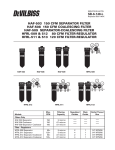
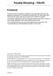
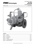
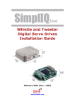
Gauge Temperature Sensor. [Inquiry] How do I remove the gauge temperature
sensor? [Mark Duval] This is the front sensor
under intake manifold runner number two with the
two round pins. A 19mm socket will not work
because of the width of the wiring connector. I
bought the stubby 19mm combination wrench and
a 19mm crow foot socket. First tried the open end
side of the stubby and although I could get it
squarely on the hex head, I could not put enough
force on the wrench to turn the sensor. Then used
the crow foot socket with a long extension. This
rotated off the hex and cracked the electrical connection at the top of the sensor.
The answer all along was to remove the sensor's molded-on electrical connector
(destroying the sensor) and gain access to the hex with an offset 19mm box
wrench or a 3/4 inch socket. [Jay Simkin] Remove the old sensor and prep the new
sensor by applying a thin coat of grease on the threads. Then apply grey pipe joint
compound (not the white, teflon-loaded joint compound) in a collar of compound
on the underside of the sensor's lip, above the threads. Keep the joint compound
away from the threads. To reinstall, gently screw the prepped sensor into the
opening in the block. Tighten snug using a 3/4" open end wrench. A 3/4" socket
will not work, as the electrical connector housing is wider than the brass hex fitting
used to secure the sensor. Check for leaks. Tighten gently if required to stop any
leaks. Replace the knock sensor using a 12mm wrench to tighten it securely
file:///C|/Users/Steve/Documents/Volvo%20FAQ%20Updated/EngineSensors.html[01/13/14 10:07:45 PM]
Engine Sensors
against the engine block. Replace both electrical connectors and reconnect the
battery negative.
[Editor] It helps to first remove assorted tubes and pipes, including the IAC valve
and the knock sensor nearby, which is merely bolted into the block.
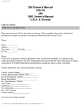
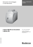
Engine Coolant Temperature Sensor. Removing the
Engine Coolant Temperature Sensor (the rear-most of the
three sensors, Volvo p/n 1346030 or Bosch 0280130032)
is a little tougher, since it is buried under intake manifold
runner number three. Two contrary removal tips: [Tip
from John Sargent] Removing the intake manifold makes
it less than a 30 minute job. Trying to R&R without
removing the intake manifold can lead to a broken
sensor. The brass hex of the ECT is 19mm. The electrical
connector is larger than the 19mm hex and a socket or
box end wrench will not fit over the electrical connector,
so you can only use an open end wrench to remove the
ECT. The wiring harness connector can be very difficult to
disconnect without removing the intake manifold. Save
yourself on both aggravations, just get an intake manifold
gasket if the sensor needs to be replaced. [Jay Simkin]
This sensor's wiring connector housing fits inside a 19mm
deep socket, which then engages the sensor's brass hex
fitting. I recently did this job, and used a 3/8" 19mm deep socket to remove the
sensor from the head. There was just enough work room between the manifold's
runners (I have small hands). I put the socket on the sensor, and then inserted the
ratchet's square protrusion into the socket. By contrast, the temperature gauge's
coolant sensor (towards the front of the head) has a wiring connector
housing wider than is the sensor's brass hex fitting. Therefore, some may need to
remove the connector housing, before removing the sensor.
Installing the Sensors. [Editor] Do NOT use Teflon tape or Teflon pipe sealer on
the threads when reinstalling since they may interfere with temperature readings
and with grounding against the block. Better to use thin coat of a conductive
grease such as OxGard or apply pipe joint compound above the threaded area.
Diagnosing ECT Failures. [Response: Don Foster, adapted to 700/900 series by
Editor] Your engine has two temp sensors -- one for the gauge (it's mounted in the
head about under intake header #2, and one for the FI (it's mounted in the head
about under intake header #3). The latter is the ECT sensor.
The sensor is an NTC thermistor -- negative temperature coefficient. As the temp
drops, the resistance rises, and as the temperature rises, the resistance drops.
Thus, if you have a broken wire, defective sensor, or bad connection (I've seen it
happen) the resistance measured by the ecu will be very high or infinite. The ECU
interprets this as minus a zillion degrees and pours in the gas
The car I saw filled the oil with gas and certainly wouldn't run. And the problem
was only a displaced spade lug in the plastic connector housing. According to
file:///C|/Users/Steve/Documents/Volvo%20FAQ%20Updated/EngineSensors.html[01/13/14 10:07:45 PM]
Engine Sensors
Chilton's (you may choose to disregard this):
The coolant temperature signal to the control unit has a great influence on the
computed injection period... For example, when the engine is being started and is
cold, the amount of injected fuel must be relatively large. [Editor:] Too rich a
mixture because of a failing ECT may lead to idle surges, high idle, poor warm
running, or other symptoms of too much fuel. See Engine Tune and Performance;
Symptoms for more examples.
If the control unit receives a signal higher than 302F (150C) or lower than -40F (40C), it will interpret the signal as a fault...the control unit will assume a substitute
value corresponding to 32F (0C) on starting and 68F (20C) when the engine has
started.
With the control unit connected, connect a voltmeter across LH ECU terminals 13
and 5 (ground) for Bosch LH 2.4 systems or terminals 2 and 5 (ground) for LH 2.2
systems. This unit is in the passenger side footwell, under the plastic cover.
Remove the cover of the large electrical connector to access the backs of the pins
for the test. Turn the ignition switch ON.
At 68F (20C) the voltage should be 2.0 +/-.5v volts.
At 104F(40C) the voltage should be 1.2 +/- .3volts
At 176F (80C) the voltage should be .5 +/- .2volts.
The resistance values between ECU pins 13 and 5, or between each of the pins on
the sensor and ground, are (by eye from the chart):
32F (0C)-- about 6000 ohms within a range of +/- 10%
68F(20C) -- about 2300 ohms
104F(40C) -- about 1300 ohms
140F(60C) -- about 600 ohms
176F(80C) -- about 300 ohms
212F -- about 190 ohms
[Response: Steve Ringlee] ECT resistance cold for LH2.4 systems should be around
6k ohms at 32 degrees F (0 deg C), 2300-2700 ohms at 68 degrees F (20 C), and
200 at 212 F (100 C). However, try checking your ECT wiring: Between pins 13
and 5 at the LH ECU (with sensor DISconnected) resistance should be infinite.
Voltage with the ignition ON and sensor connected, measured between pins 13 and
5, should be:
0 C=around 3 volts +/-.5v
20C=around 2 volts +/- .5v
100C=around .3 volt +/- .1v
If these aren't correct, check the connections in the ECT wiring harness. Check
engine ground connections at the intake manifold. If the voltage is zero, your ECU
is at fault.
ECT Wiring/Connector Failure. [JonP] my 1990 LH2.4 still ran rich, smoked,
stumbled, and set codes 1-1-3, 2-1-3, and others refering to rich mixture.
However, during disassembly I discovered the female connector for the ECT was
file:///C|/Users/Steve/Documents/Volvo%20FAQ%20Updated/EngineSensors.html[01/13/14 10:07:45 PM]
Engine Sensors
damaged by one of the sensors spade pins when someone pressed the connector
on incorrectly. The pin missed one of the female clips and mashed it. The local
Volvo dealer parts manager has been very helpful: I described the ECT connector
problem and he gave a new connector to me with a couple of insulated pinch
connectors and his tips for how to make the splice....no charge. He did say if this
splice didn't fix it then he thought it was a failed ground in the ECU (ECM) for the
fuel injection. He said the bad connector could also cause a bad ground problem at
the ECU.
960 B6304 ECT Sensor Failure.
[Tip from Tom Haywood] '95 960 B6304 with Motronic 1.8: the symptoms, in my
case, were sudden very high idle surges (2500-3000 RPMs) while sitting at idle and
hot-start problems. This engine has two coolant sensors; the rear coolant
temperature sensor is Volvo#68 49 350 (SWF#602.101) and apparently plays a
role in fuel injection and various timing functions. It is similar to the front one
(FRONT Volvo#35 45 031), but without the 5-inch connector wire. Testing the
sensor in heated water indicated normal operating ranges until reaching
180deg.(220 ohms) .....at which point the circuit would open completely (infinite
ohms). When the brass housing would heat up it would pull the connector pin away
from the thermistor leg. I have further learned that these symptoms can also point
to the wiring to this sensor, because of the location between the fire-wall and hot
engine parts. I could suggest to anyone with this engine to keep a new sensor
handy, because it looks like the car will be dead-in-the-water when it fails. This
sensor is at the rear of the head and requires a mirror taped to the firewall and a
19mm open-end wrench for removal (drain the antifreeze and remove the heater
hoses first). Work from the top of the engine, standing on a stepstool and using a
pillow on which to kneel. It has a 2-pin D-type connector mounted right on the
brass housing. The large size of the connector keeps you from being able to get a
good box-end wrench on it, but mine was not very tight anyhow (just very hard to
get to).
[Tom Irwin] Those rear ECT's are a pain in the ass. The harness (surprise!) allows
very little slack. As the insulation degrades, the tension on the wires just pops it
off. Then the epoxy potting around the sensor starts to go.
Throttle Position Switch. [Editor] This applies to both Bosch LH2.4 and Regina
systems.
Symptoms of Failure:
High idle at startup or uncontrolled idle above
750 rpm.
Diagnosis:
This switch is a simple device: at either extreme
of motion, an internal switch is closed and you
will see continuity between one outer connector
and the middle ground connector. Disconnect the
file:///C|/Users/Steve/Documents/Volvo%20FAQ%20Updated/EngineSensors.html[01/13/14 10:07:45 PM]
Engine Sensors
switch connector and jump from one side connector to the middle ground
connector. If idle returns to normal, then the switch is at fault. The switch is not
repairable.
Adjusting the TPS:
To adjust the TPS:
1. Remove the throttle body from the car and loosen the
TPS adjustment screws
2. Hold the throttle plate and keep it from moving.
Rotate the TPS clockwise, then counterclockwise until
a click is heard. Continue rotating until it stops but
does not cause the throttle plate to move. This can
best be done by inserting a .25mm feeler gauge
between the lever and the adjustment screw. Secure
the screws.
3. Proper adjustment is obtained when you open the throttle plate and insert a
feeler gauge at the throttle stop screw:
When you close the throttle against a .45mm feeler gauge, no click is
heard from the TPS
When you close the throttle against a .15mm feeler gauge, a click is
heard.
Oxygen Sensor
Theory and Operation
1. Oxygen sensors should last over 100k miles under ideal conditions; various
contaminants will shorten that considerably.
2. [Excerpts from Underhood Service magazine, Nov 2000, et al]
The O2 sensor is mounted in the exhaust manifold to monitor how much unburned
oxygen is in the exhaust as it exits the engine. Monitoring oxygen levels in the
exhaust is a way it gauges the fuel mixture. The sensor tells
the computer if the fuel mixture is burning rich (less oxygen)
or lean (more oxygen).
Although O2 sensors are amazingly rugged considering the
operating environment they live in, they do wear out and
eventually have to be replaced. The performance of the O2
sensor diminishes with age as contaminants accumulate on the sensor tip and
gradually reduce its ability to produce voltage. The aging process is caused by a
buildup of contaminants on the sensor's zirconium sensing element. If the engine
burns oil, phosphorus deposits may contaminate the sensor and catalytic converter
over time. If the engine has an internal coolant leak (cracked combustion chamber
or leaky head gasket), silicone additives in the antifreeze can become a source of
contamination. Contamination Caution: If you use silicone-based RTV gasket
file:///C|/Users/Steve/Documents/Volvo%20FAQ%20Updated/EngineSensors.html[01/13/14 10:07:45 PM]
Engine Sensors
material anywhere on the engine, especially in manifolds or valve covers, make
sure the tube says "sensor-safe RTV compound". Silicone from the gasket can
contaminate your oxygen sensor. According to the Robert Bosch Corp., replacing a
degraded oxygen sensor with a new one will increase fuel efficiency by 10% to
15%. Don't use silicone sprays anywhere near the intake system. And Airtex
Automotive reports replacing degraded oxygen sensors has the potential to reduce
a vehicle's emissions of hydrocarbons (HC) by 23% and carbon monoxide (CO) by
33%. In fact, an EPA study found that 70% of the vehicles that failed an I/M 240
emissions test needed a new O2 sensor. Bosch recommends a professional service
technician check a customer's oxygen sensor on a regular basis: every 60,000 to
100,000 miles for a heated three- or four-wire sensor.
The O2 sensor works like a miniature generator and produces its own voltage when
it gets hot. Inside the vented cover on the end of the sensor that screws into the
exhaust manifold is a zirconium ceramic bulb. The bulb is
coated on the outside with a porous layer of platinum.
Inside the bulb are two strips of platinum that serve as
electrodes or contacts. Between the electrodes is a solidstate electrolyte made up of a zirconic ceramic material
that acts like a galvanic battery electrolyte under certain
conditions. When the sensing element is cold, the
zirconia material behaves similar to an insulator. At
elevated temperatures, the zirconia material performs
more like a semiconductor, and can generate a
characteristic voltage output on the sensor connections.
The outside of the bulb is exposed to the hot gases in
the exhaust while the inside of the bulb is vented internally through the sensor
body to the outside atmosphere. Newer-style O2 sensors breathe through their
wire connectors and have no vent hole. This is why grease should never be used on
O2 sensor connectors because it can block the flow of air.
The difference in oxygen levels between the outside air and the exhaust within the
sensor is what causes voltage to flow through the ceramic bulb. The greater the
difference, the higher the voltage reading. Typically, an oxygen sensor will generate
up to about 0.9 volts when the fuel mixture is rich and there is little unburned
oxygen in the exhaust. When the mixture is lean, the sensor's output voltage will
drop down to about 0.1 volts. When the air/fuel mixture is balanced or at the
equilibrium point of about 14.7 to 1, the sensor will read around .45 volts. When
the computer receives a rich signal (high voltage) from the O2 sensor, it leans the
fuel mixture to reduce the sensor's reading. When the O2 sensor reading goes lean
(low voltage), the computer reverses again, making the fuel mixture go rich. This
constant flip-flopping back and forth of the fuel mixture occurs at different speeds
depending on the fuel system. Engines with multiport injection do this five to seven
times per second at 2,500 rpm.The O2 sensor must react quickly to these changing
fuel conditions in order for the computer to maintain the best average air/fuel ratio.
As sensors age, they become sluggish and respond more slowly to changes in the
air/fuel ratio. This may cause emissions and fuel consumption to rise.
Before it will start to generate a voltage signal, the oxygen sensor must be hot usually from about 450d F to 600d F or even higher. The sensor incorporates an
internal electric heating element to bring the O2 sensor up to operating
file:///C|/Users/Steve/Documents/Volvo%20FAQ%20Updated/EngineSensors.html[01/13/14 10:07:45 PM]
Engine Sensors
temperature quickly (under 35 seconds). Internal heating elements usually operate
continuously while the engine is running to maintain an operating temperature of
approximately 1292 degrees Fahrenheit to 1472 degrees Fahrenheit. Heated O2
sensors operate at a more consistent temperature and allow greater flexibility of
placement locations in the exhaust system. Three and four wire sensors have this
heater installed: two wires for the heating element, one signal wire and possibly a
ground wire. Oxygen sensors that are not equipped with a ground wire must have
a well-grounded exhaust system to complete the sensing circuit. Basic electrical
wiring circuit checks should be made to determine if the vehicle's wiring harness
has good continuity and is free from short circuits.
The ECU will set an O2 sensor diagnostic code if the sensor does not produce a
voltage signal, stays rich too long, stays lean too long, does not switch rich/lean
(center too long), or does not switch rich/lean fast enough. If the sensor dies
altogether, the result can be a fixed rich fuel mixture. The rich mixture therefore
can cause the converter to overheat, resulting in severe damage and higher repair
costs for the driver. As one aftermarket manufacturer points out, sensor checks
come down to paying a little now or a lot later. One way technicians can test
oxygen sensors is to see if the sensor's output voltage changes when the fuel
mixture changes. When the mixture is lean, the sensor's output voltage should be
low (down around 0.1 volts), and when the mixture is rich the sensor's output
should be high (up around 0.9 volts). A steady low voltage reading or no voltage
reading would indicate a bad sensor.
Making the fuel mixture artificially rich by adding propane into the intake manifold
should cause the sensor to respond almost immediately (within 100 milliseconds)
and go to maximum (0.9v) output. On the other hand, creating a lean mixture by
opening a vacuum line should cause the sensor's output to drop to its minimum
(0.1v) value.
Although a technician can read the O2 sensor's output with a scan tool or digital
voltmeter, the transitions are hard to see because the numbers jump around so
much. An analog voltmeter is better for viewing transitions, but may not respond
quickly enough on systems with higher transition rates. So the recommended
instrument for observing the O2 sensor's voltage output is a digital storage
oscilloscope (DSO). A scope will display the sensor's voltage output as a wavy line
that shows its amplitude (minimum and maximum voltage) as well as its frequency
(transition rate from rich to lean).
A good O2 sensor should produce an oscillating waveform at idle that makes
voltage transitions from near minimum to near maximum. If the sensor doesn't
flip-flop back and forth quickly enough, it may indicate a need for replacement. If
the O2 sensor circuit opens, shorts or goes out of range, it may set a fault code
and illuminate the Check Engine or Malfunction Indicator Lamp. If additional
diagnosis reveals the sensor is defective, replacement is required.
Specific Diagnostics and Tests
See the specific diagnostic procedures in the FAQ Fuel Injection section on Oxygen
Sensor Diagnosis.
[Inquiry:] Anybody know what the resistance of the O2 sensor heater should be?
file:///C|/Users/Steve/Documents/Volvo%20FAQ%20Updated/EngineSensors.html[01/13/14 10:07:45 PM]
Engine Sensors
mine says 2.2 ohms. With only the green wire connected to the ECU I get a pretty
stable .52 volts, which I have read in the archives to be the ECU reference voltage.
Hopefully all is well at that end. If I connect the heater (there is ~13.5v on the
harness side, btw) the sensor voltage decays over about 30 seconds to .01 volts.
At no time does voltage sweep from .3 to .7 v. Also, can you replace the heated
one with non-heated? A Bosch Ford 5 litre sensor is $97.80 (cdn) at a local import
autoparts store, the Volvo sensor is $280 something.
[Response 1: Abe Crombie] That is the right resistance on the heater. Use a digital
voltmeter with impedance at least 10 megohm. Before you replace the sensor
warm up engine and attach the voltmeter positive probe to O2 sensor lead (the
green wire into pin 24 on the Fuel Injection ECU, or using a sharp probe tip into the
black sensor wire at the firewall connector), the negative probe to a convenient
chassis ground, and leave the ozygen sensor connected. Then turn on the engine
and momentarily pinch the rubber return line behind fuel pressure regulator. If the
voltage of sensor goes to .7-.9 V then look for something other than the sensor
causing a lean condition. A faulty sensor can give you the low V reading but an air
leak or defective MAF sensor can do the same. With regard to heated (three wire),
versus non-heated (two wire), yes and no. The heated sensors are used to keep
the signal active while idling. Idling in cold weather primarily, the sensor will fall
below its 600F temp at which the reaction that makes it output voltage begins to
work. If it were to stay above this temp the non-heated would be okay. There are
different sensors out there also. Most all the Bosch up to 92 have the same output
voltage at the same O2 gradient. After 92 there are differences in some of the
applications in this respect.
Regina vs. Bosch Oxygen Sensors
The Bendix/Siemens Regina fuel injection systems use a titania-type sensor
which varies resistance and is not interchangeable with the Bosch zirconia
units which create a varying voltage signal. This sensor does not work with
a .5 V reference out of the ECM as do the Bosch versions. The Regina unit
uses the heater power supply to feed a sensor circuit which responds to O2level variations. The Bosch zirconia unit measures an electrochemical
reaction and the heater merely maintains the temperature stability of the
sensor and does not supply current to be modified and used as output
signal.
Compared to the more common zirconia O2 sensors, titania sensors have
three advantages: (1) they don't need an air reference (there is no internal
venting to the outside atmosphere to plug up); (2) they have a fast warmup time (about 15 seconds); and (3) they work at lower exhaust temperatures
(they won't cool off at idle and they can be located further downstream from the
engine or used with turbochargers). See the notes below regarding the use of
generic sensors in Regina cars. A direct replacement for the Regina sensor is an
NGK 25002: Amazon has a good price on these.
When is Replacement Recommended? [Tip from Import Car Magazine, Apr
2003] Replace if:
Antifreeze contaminates oxygen sensors. Oxygen sensor replacement is highly
recommended after replacing cracked cylinder heads, leaking intake gaskets or
file:///C|/Users/Steve/Documents/Volvo%20FAQ%20Updated/EngineSensors.html[01/13/14 10:07:45 PM]
Engine Sensors
leaking cylinder head gaskets.
Oil contamination also ruins oxygen sensors. Oil ash accumulating on the
sensor thimble or wicking through the sensor wire may cause erroneous
air/fuel ratio readings.
Other Conditions Causing Oxygen Sensor Malfunctions:
Leaking exhaust manifolds and air injection systems contribute to faulty
air/fuel measurements by the oxygen sensor because they dilute the exhaust
gas stream with atmospheric oxygen.
Leaking fuel pressure regulators or leaking vacuum hoses and intake gaskets
often will cause a no-switching condition at the oxygen sensor.
Replacement Procedures:
Opening Caution. [JohnO] If doing it yourself, do it with a cold engine as many
O2 sensors are more likely to cross-thread if done hot (although not so much so
with Volvos). If you doubt your skills with this, just take it to dealer and pay them
to replace it as it won't be that much for the labor (about 1 hour).
Tool Notes. Which tool do I use to remove the O2 sensor? [Paul Seminara] Us a
crows foot or special slotted O2 sensor socket or adapted open/closed end wrench.
Replacement Procedure. [Editor: Tom's notes apply to a 960 but the procedure
is similar for 740/940] [query] I'm planning to change my O2 sensor on my 960
wagon. Where is that thing? How tough of a time will I have in removing it because
of heat-related seizing. [Response: Tom Irwin] OK, if you are w/o a shop and
hydraulic lift, I recommend the following... FOUR JACKSTANDS Rated to 3,000
pounds apiece or better. I've been lifting the car under it's mid-chassis
reinforcement with a large wide-saddle jack. A skinny jack will damage the
underside of your car... Lifting the whole side, place 1 jackstand each under the
corner lifting points, at FULL-EXTENSION... do the drivers side first... Ditto the
passenger side, BUT LEAVE the jack in place and lower it maybe 0.5" so it is a
back-up, in case the jackstands fail, but it is NOT bearing any load... (could cause
they whole deal to shift.) Lay down a HEAVY piece of corrugated cardboard... Let's
you SLIDE in and out from under the car real nice.
The O2 sensor is screwed in to the CAT, up on top, there are four wires. FIRST! Go
open the hood and locate the O2 connector... it's kinda near the oil dipstick tube,
about half-way down. It should be clipped to a metal standard...release it...there is
enough slack to lift the whole assembly up higher for a better look. It is a BLUE
plastic connector with a RED slide-Lock passing through it's mid section. Use a
small thin screwdriver under the looped bail of the red slide lock and pry it gently
to the side, extend it as far as it will go. Separate the 2 blue plastic halves make
sure that the end of the harness that goes down below to the O2 sensor is not wire
tied anywhere.
Go back Down Under the car, pull the wire down and cut any cable ties holding it
to the dipstick or elswhere. Now on the left side of the transmission there are 3
plastic snap-lock clips holding the wires to the transmission pan. Squeeze them
from the inside with a thin nosed plier and release all three. On the UPPER,
TRAILING EDGE of the transmission tail bracket, there are 3 10mm headed bolts
file:///C|/Users/Steve/Documents/Volvo%20FAQ%20Updated/EngineSensors.html[01/13/14 10:07:45 PM]
Engine Sensors
holding the wire to the bracket. Remove all three. A small 1/4" drive ratchet is
great for this. Then remove the ONE speed nut holding the wire up on a heatshield
in front of the CAT. Follow the wire... THAR she IS... sticking out of the top of the
CAT, in front of the honeycomb. It is a 22mm facet on the base of the sensor. Get
a 22mm socket with the sidewall slotted out for the wire to pass thru (Editor:
known as an oxygen sensor wrench)... if you can... but I just squirted a bit of PB
Blaster on the base and let it sit for a few minutes.
I ended up using a 22mm spanner wrench open end to the sensor.. It cracked free
quite easily... you may be so lucky.. Then you just un-screw it. I know this is
trite....but....Re-Assembly IS reverse order. REALLY! [Tip] In truly corroded cases,
heating the pipe or converter bung with an oxyacetylene torch should loosen the
screwed-in sensor. [Note from WBain] Use an anti-seize compound on the threads
(if the sensor did not come with any.) It will make any future disassembly easier.
[Caution from David Hunter] Also make sure you are not cross threading it - easy
to do on the O2 sensor.
Replacement: Use of Generic Sensors.
Generics. [Editor] You can install a generic Bosch or other three-wire heated sensor
instead of the more expensive Volvo OEM sensor in Bosch LH systems, but you will
have to splice in the connector. The separate FAQ File on sensor replacements
shows some wire length and splice information. Bosch model numbers 13953,
13942, and 13913 are reputed to work depending on your year and engine (same
sensor listed as for Ford 5.0 V8 Mustang engine but different harness lengths:
check the Bosch site for applications and see the FAQ File on sensor replacements).
Note: See the table of generic replacements compiled by Brickboard members.
Note that several correspondents have noticed hesitation on acceleration after
installing generic sensors due to peak voltages of 1.3 instead of 0.9. Replacing the
sensor solved the problem.
OEM in 93+ Bosch. [Frank] In March of 1993 Volvo switched from a three wire O2
sensor to a four wire sensor. The three-wire generic sensors are not
interchangeable with the newer four-wire applications.
Regina. If you have a Regina-equipped car, use a sensor specifically engineered
for Regina systems. Regina cars through 1993 use a Volvo -394 sensor which is
the same as NGK OTA4F-B. The Walker catalog lists 250-23811 as a direct fit
replacement for Regina systems. Note: many aftermarket sites, including
FCPGroton, do not distinguish between Bosch and Regina and claim that the
Bosch unit "fits all". Not true. To be sure, buy the NGK unit for Regina which is
listed at their website (they confuse 8 and 16 valve cars, but the correct Regina
sensor is shown.)
Installation. [Ken] To install the generic sensor, you will need to cut the wires on
your harness and splice them to the sensor wire. Crimping is recommended,
instead of soldering, because solder weakens stranded wire subject to heat and
vibration by decreasing its fatigue life. The NGK website also recommends crimping
using heat shrink tubing to protect the crimp. Buy 3M crimp connectors with
integral heat shrink tubing (Walmart has these). Do not use silicone dielectric
grease on the connection since silicone contaminates the sensor.
Code 2-1-2 "Faulty Oxygen Sensor" in 960 Cars. [Rafael Riverol] If the check
file:///C|/Users/Steve/Documents/Volvo%20FAQ%20Updated/EngineSensors.html[01/13/14 10:07:45 PM]
Engine Sensors
engine light on the dashboard lights up and you read OBD I diagnostic code 2 1 2
(faulty oxygen sensor (O2) signal) in your 960, undo the red and blue four way O2
connector near the oil dipstick and check inside. The metal spades in the male
connector are surrounded by silicone like material which crumbles, particularly after
you apply electronic connection cleaner or the like. The particles can fall within the
male and female connection, even inside the female connector contacts, and cause
a faulty O2 sensor signal. Take out the loose material with sharp tweezers. Make
sure all contacts are clean and undistorted and connect back together WITHOUT
using silicone dielectric grease because of low signal voltages. Clear the codes. This
procedure should eliminate the faulty signal.
Crank Position or RPM Sensor.
B2XX Series Engines. Symptoms of Failure: No Hot Restart. Suppose the car
already has the upgraded silver-terminal fuel pump relay but won't restart promptly
after a hot soak. Take an educated guess
on a weak crank position (RPM) sensor. If
you have Bosch LH2.4, then replacing this
permanent-magnet sensor located in the
top of the bellhousing fixes many hot
restart complaints on 700/900s. [Tip from
HansW] Check the lead to the sensor: it
can rub against engine components or fray
from flexing and expose the wiring. Newer
sensors come with plastic cable holders to
prevent this. [Editor] Many Regin-equipped
cars use the same sensor.
Testing Bellhousing RPM Sensor. [Inquiry:] I decided to find and remove my
flywheel sensor. Externally it's in perfect condition. The cable and ends are pristinelooking. Is there a way to test it with a multimeter?
[Response: Ivan K] To find the sensor, stand at the left or drivers' side front fender
and look behind the rear of the cylinder head down towards the bell housing . The
crank sensor sits in a hole at the very top of the bell housing and has a black 1/4
inch diameter wiring harness leading into it down from the firewall harness. Often
these rpm sensors fail intermittently, usually when hot. This makes them hard to
test. Since the sensor is cheap enough, just replace it. With high mileage cars, it's
only a matter of time before they fail.
[Response] Measure the signal while the sensor is still installed by unplugging the
sensor at the cable connections at the firewall to the drivers side of the engine.
Measure voltage here as the engine is being cranked. Use a low voltage setting on
a digital volt meter, preferably in an alternating current setting if available in a low
voltage setting. If no signal is detected, the unit is suspect. The other simple
measurement is to unplug the unit (without removing it from its location behind the
engine on top of the transmission housing). Check all 3 terminals for resistance or
an open circuit. The new sensor measured about 160 ohms between the center lug
and a side lug (red and blue wires). The black wire is the grounded shielding wire.
My old defective unit had no continuity and no measurable resistance.
file:///C|/Users/Steve/Documents/Volvo%20FAQ%20Updated/EngineSensors.html[01/13/14 10:07:45 PM]
Engine Sensors
Removal of Bellhousing RPM Sensor. [Tips from Jay Simkin, George Campbell
and others] The rpm sensor is awkward to access as it is below the cylinder head
on top of bell housing. It can be removed by using 21" of 1/4" or 3/8" extensions,
then a universal joint, a 3" extension, and a 10mm standard depth socket to turn
the retaining 10mm hex head screw. OR you can use a 10mm combination wrench
with a racheting box end ("GearWrench"). Note that some cars use an 8mm bolt
head.
Use a flashlight to locate the sensor and the bolt. You'll have to peer at the thing
from the passenger side fender, looking over the air conditioning pipes. It's below
the distributor, on the top of the bell housing. Carefully put your left hand between
the engine block and firewall, and locate the retaining bolt head and the wire from
the sensor with your fingers. The reason for this is so you can orient yourself to its
exact location. While you're removing and replacing it, you won't be able to see
what you're doing, so you'll need to visualize it in your mind. Then clean the area
around the sensor using brake cleaner and spray it with penetrating oil.
[Using the Socket and Extensions to Loosen] Without inserting the ratchet in the
extension end, pass the tools between the firewall and the aluminum-colored airconditioning pipe. Once the tools enter the space beside the engine, bend the
universal at 60 degree angle. Pass the tool string behind the engine block. There is
a black cable that can be pushed out of the way. The 3" extension and 10mm
socket will align pretty easily with the top of the hex head machine screw. Set the
socket on the machine screw head. Gently, insert the ratchet into the extension
string. Turn gently to remove the machine screw. Remove the tools. Use your left
hand to grip the sensor.
[Using the Ratcheting Wrench] Orient the wrench so that it will loosen the bolt, and
then using your left hand, with your index finger placed over the ratcheting box,
insert your hand and the wrench carefully behind the engine block and place the
racheting box end over the retaining bolt head. The reason for putting your index
finger over the box end is to make it easier to find that bolt head, since you won't
be able to see. Carefully re-orient your hand on the wrench, trying not to pop the
box end off the bolt head and then loosen the retaining bolt. You'll be able to move
the wrench only about 10 degrees, so keep going until the ratchet won't loosen the
retaining bolt any further, then remove the wrench and your left hand. Insert your
right hand behind the engine block, thumb down, and use thumb and index finger
to finish removing the retaining bolt. Keep one finger on the bolt at all times. You'll
only be able to manage a partial turn each time. When the bolt is free, carefully
remove it and take it out from the narrow space. Put it somewhere safe.
[Removing the Sensor] The sensor usually will come free as soon as the screw is
removed. If it does not, grip it close to where it enters the housing - not at the
top, into which the wire enters - and pull straight up. Do not pull on the wire. If the
sensor will not come out, you may need to break any seal between the sensor base
and the bell housing. Use penetrating oil. Turn the sensor gently about 1/16" turn,
in either direction. You may rock the sensor gently, but no more than 1/16", sideto-side. Do not use any tool or brute force and DO NOT PRY since the housing is
plastic (see the Cautionary Note below). The sensor goes only about 3/4" into the
bell housing. The sensor has smooth sides and no locking lugs, so it is removed by
pulling straight up. Do not use brute force: if the sensor snaps and plastic
fragments fall into the bell housing, the transmission will have to be removed to
allow removal of the fragments. Disconnect the sensor at the connector near the
driver's side firewall. Pry the spring clip loose and put it safely somewhere. It's
file:///C|/Users/Steve/Documents/Volvo%20FAQ%20Updated/EngineSensors.html[01/13/14 10:07:45 PM]
Engine Sensors
small and easily lost. You can fish the plug through the zip tie on the firewall, but
it's not all that easy. Move the other wires, etc. until you get it out.
Caution: Some Cars Have a Flimsy Sensor Mounting Bracket. [Another Tip]
Trouble started when I couldn't get the old sensor out of the hole into which it fits
over the flywheel. Where it's located makes it hard
to get much of a grip on it. I tried rotating it in the
hole to free it and then prying it up with a
screwdriver. To make a long-story short, it's not
mounted in the beefy Volvo bell housing like I
thought, but in a flimsy, Fiat-like, aluminum casting
that bolts into the back of the block. And very easy
to break, I've discovered. And designed so you
need to separate the bell housing from the engine
to R&R it!!! Moral of the story is go easy on a stuck
sensor
[Chris Herbst] NEVER PRY the RPM sensor out of
the bracket. The poor quality bracket that they use
to hold the sensor is SO weak that can break if you force the sensor around. Prying
side to side on the sensor can break either the bracket or the sensor, leaving you
helpless to do anything but pull the trans back to replace the bracket. When you
really pry that thing is usually when it breaks. But because those brackets are so
flimsy, it can still get you when you don't expect it. Usually (99 out of 100) is a
piece of cake. But when you're the one who has #100... it sucks. Just be careful
and you'll be fine.
Turn it lightly back and forth to remove it, but don't force it at all. Wait until it
moves. On a standard trans cars use a tiny bit of silicone spray to get the thing
out, and work it gently back and forth until it gradually loosens. If it is an
automatic, get an Easy Out screw extractor into it, then douse the thing with
PBlaster penetrating oil and wait for it to work its magic. The penetrant won't hurt
anything like the clutch on the standard trans car. On the other hand, you want to
avoid harming the timing ring on the automatic, because it is not very strong. You
still run the risk of demolishing the bracket if you pry at it too hard, so make sure
you are patient and let any penetrant or silicone get in there before you pull it.
Once they move side to side, they can gently be removed. This sometimes takes a
while, but the rewards are that you don't have to pull the transmission. On
installation, put a light coating of grease on the perimeter of the sensor where it
contacts the bracket. That will make your life a lot easier when you go to get it out
of there next time. And if you have the trans out for any reason, take the RPM
sensor out--whether or not you reuse it--and coat it LIGHTLY with a film of grease.
That will avoid the problem, should the sensor need replacement in the future.
[Editor]
Reinstallation. [George Campbell] Don't bother trying to fish the new sensor's
plug through there. It's a waste of time. Just zip tie the wire to the other wires
after installation. After plugging in and securing the new sensor, carefully route it
and let it drop behind the distributor, near where it will go.
Coat the 10mm bolt threads and face with antiseize. Insert the retaining bolt in the
sensor's extension. Using your left hand, put your index finger on the top of the
file:///C|/Users/Steve/Documents/Volvo%20FAQ%20Updated/EngineSensors.html[01/13/14 10:07:45 PM]
Engine Sensors
retaining bolt, grasp the sensor with your thumb and second finger and carefully
maneuver the sensor into position, lowering the sensor into the hole in the bell
housing. You may have to fiddle a bit, but if you oriented yourself well before
starting, you'll find the hole easily with the part by feel. Keep your index finger on
the top of the retaining bolt as it rises when the sensor enters the bell-housing.
Gently turn the assembly until you feel the retaining bolt find its threaded hole. It's
hard to describe, but you'll feel it. Very carefully, move your hand, and work with
thumb and forefinger to start the bolt in the threads. If you don't have lots of
experience, this will be the most difficult part of the job, since the quarters are so
tight and since you can't rotate the bolt much. Don't rush and don't accidentally
pull the bolt out and drop it. The bracket is deep enough to keep the bolt from
falling out on its own. Just don't raise the bolt. Once you've started the threads
with your left hand, switch to your right hand, thumb down, and continue turning
the bolt head to tighten it. When you can no longer move it with your fingers, use
the ratchet box end of the wrench to finish the tightening job.
Broken Sensor Bracket Removal. [Editor] The usual solution to a broken crank
sensor bracket is to pull the transmission and replace it. However, I have seen
reports of using a Dremel or drill along with a shop vac to suck up metal chips, to
enlarge the bellhousing opening and remove the bracket screws before installing a
new sensor bracket. This is done without pulling the transmission. [Robert] Drill
and a dremel worked fine. Tried to pull tranny out but got stuck on one pesky bolt.
So I had to abort and went for a drill. Was done in 2 hours and back on the road
today. I only had to trim about half an inch on each side.The bracket itself is only
about $30.
Bent Flywheel Sensor Plate. The sensor uses a toothed plate mounted on the
flywheel to sense revolutions; if this is bent, it will not record the pulse. Odd
symptoms, including difficult starting and poor power, may result. Bending
commonly occurs when working around the flywheel or when jamming the ring gear
to change the timing belt, so be VERY careful when working in that area.
B6XXX Series Six Cylinder Engines
[Tip: Rob Bareiss] The 960 (B6304) engine uses a sensor mounted at the back end
of one of the camshafts. It's in the same position as the distributor on an
850/S/V70 5cylinder. Since the 960 has no distributor, it uses this thing instead.
Also saves a bunch of space at the back of the engine. Probably should consider it
a regular service item, as with the 4-cylinder models. Replacing it is probably
cheaper than having the car towed one time... Removing it is similar to the B23X
engines except for the wiring clip on the firewall.
[DanR] To get the connector off the bracket, all you need is a fairly small flat
bladed screw driver. Pry away the metal collar that surrounds the connector; it has
a clip that snaps in place. The part that snaps in is on the underside of the clip. If
you break the plastic shells holding it together, they are replaceable from the
dealer. On reinstallation, make sure you insert correctly the two wires from the
trans oil temp sensor.
Knock Sensor.
file:///C|/Users/Steve/Documents/Volvo%20FAQ%20Updated/EngineSensors.html[01/13/14 10:07:45 PM]
Engine Sensors
Symptoms of Failure. [Tips from Marc] The car starts fine and will run for 2 miles
and then lose power. It never stalls just won't move. If I shut it off and
immediately restart it, it will run fine again for another 2 miles and so on and so
on. When it runs fine, with a timing light hooked up on acceleration the timing will
retard 1 or 2 degrees before it advances. If I check it when the problem is occuring
it will retard 6 or 8 degrees before it tries to advance. Solution: new knock sensor.
[Other symptoms] Retarded timing, acting as though no fuel is reaching the engine.
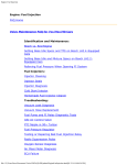
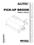
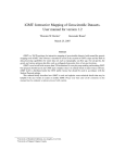
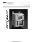
Sensor Styles. [John Sargent] The knock
sensor is located on the cylinder head under
the junction between number two and three
intake manifold runners. It is next to the two
coolant temperature sensors also bolted to
the head. LH 2.1, LH 2.2, and LH 2.4 all use
the same knock sensor, offered in two interchangeable styles that may be used on
the red engines. Type 1 is on the left in the photo on the right, and Type 2 on the
right. The only difference in the parts is the torque for the bolt holding the sensor
to the block. Type 1 has the flat top, and the fastening bolt is torqued to 8 ft-lbs
(11Nm), and Type 2 has the domed top and the fastening bolt is torqued to 15 ftlbs (20Nm). If you use anti-seize paste, reduce the torque setting by 30-40% to
account for the lubrication by the paste.
Operation. [Inquiry:] How do I test the knock sensor? [Response: Abe Crombie] If
there is not a fault code for it then it is okay. The ignition control unit tests it every
time you exceed some thing around 3000 rpm with
moderate to high throttle. If it is not torqued
properly it might not be as sensitive as it should or
be overly sensitive. Torque is 8-11 ft-lbs. It produces
a high voltage pulse when it senses the shock wave
in the range of combustion knock. The voltage level
is proportional to the severity of the knock. It will
read 1.5 or greater megaohms but this is not really
an effective test, only the control unit detecting a
sensor signal when the conditions would absolutely
assure a signal would be made is the real check. The
knock sensor test by whacking on block (better than
on the intake) next to knock sensor (see Duane's
note below) is only effective on early Chrysler systems with the throttle opened as
the closed throttle signal is supplied to Chrysler ignition ECU and it cancels knock
sensor retard activity. If you have Bosch ignition systems you can't do the whack it
and watch it test for knock sensor operation. The Bosch systems are cylinder
specific and you would have to knock within a few crank degrees of a given
cylinder firing and be monitoring the timing light attached to that cylinder's plug
wire. I don't think any of us are that good.
[Tip for Chrysler Ignition Systems from Duane Hoberg] On the right side of the
engine, in the area above and to the rear of the oil filter, tap the block with a metal
faced hammer while observing the timing with a timing light. The timing should
retard 6 degrees then return. If not then the sensor or the circuit in the control box
is bad. When installing the new knock sensor, use thread lock. Apply too much
torque and the sensor becomes sensitive as it is prestressed and reacts to normal
file:///C|/Users/Steve/Documents/Volvo%20FAQ%20Updated/EngineSensors.html[01/13/14 10:07:45 PM]
Engine Sensors
engine vibration. When this happens you will idle fine but above idle run at
retarded timing all the time. Acts like poor fuel delivery and doesn't like hills.
Diagnosis. [Additional Tips from Dave Stevens] Procedures for dealing with
suspected knock sensor problems for an LH 2.4 system with EZ116-K ignition.
Tests for other systems will be similar. Check the wiring diagram for your particular
model and year to verify connector pins and wire colors. When no knock sensor
signal is detected the EZK ignition system defaults to full spark retard. (see also
Engine Performance)
1. OBD ignition trouble code 1-4-2 Missing signal from knock sensor
2. OBD fuel system trouble code 3-1-2 Missing knock sensor signal
3. The fuel system control unit (FCU) isn't getting the knock sensor signal from
the ignition unit (ICU) at start-up.
4. Poor performance and acceleration due to excessively retarded timing
5. Over-sensitive knock sensor possibly due to over-torqued or failed knock
sensor.
Cheap gas and heavily carboned engines may cause misfiring to the point that the
knock sensor signal is not believed by the ECU. Wiring and the knock sensor itself
are by far the most common sources of knock sensor problems. [Les Daniels] If
this piezo detector fails, it goes open circuit and the ECU 'thinks' that a massive
retarding of ignition called for - hence the drop off in performance. On carb models
there can be backfiring as well.
Knock Sensor Testing:
The knock sensor can only be tested dynamically for proper waveform output with
an oscilloscope. Unless it makes you feel useful, there is no point in tapping on the
block to simulate knock sensor activity. The voltage output of the piezoelectric
quartz is too small and brief for normal measurement and, furthermore, the newer
ignition systems won't be fooled into changing the timing as they selectively only
detect knocking that would coincide with a misfire.
Start by making sure any engine diagnostic codes are for real by resetting the
trouble codes (or disconnecting the battery) and wait to see if they reappear. Then
do the physical and electrical checks below. If all other tests check out you may
want to swap in a known good knock sensor on spec. Failing that an ICU swap may
be in order. Only in desperation should the FCU be swapped on spec.
Physical checks:
1. [Les Daniels] One fault with these detectors is that the plastic housing 'cooks'
and then the detector basically falls to pieces.
2. Check that the knock sensor (on the block, left side, down below intake
runners #2 and #3) is properly connected to the wiring harness. It's easy to
leave this connector off if you've been working on the engine.
3. Make sure the wiring connector for the knock sensor (green with black or
brown wire) has not been accidentally switched with the block temp sensor
connector (red/black with grey/white wire). The connectors are alike.
4. Make sure all connections are making good contact (straighten bent/separated
contacts, check pins are fully seated by pushing in from back side). Remember
file:///C|/Users/Steve/Documents/Volvo%20FAQ%20Updated/EngineSensors.html[01/13/14 10:07:45 PM]
Engine Sensors
to check the associated connector block at the strut tower or firewall. Make
sure all connections are clean and protected from oxidation. Inspect for
deteriorated/damaged wiring. Use an approved type of electrical contact
cleaner. Squeeze dielectric grease into both sides of the connectors before reassembly.
5. [Charles Dinges] Make sure the wiring feed to the knock sensor is not close to
the alternator: anecdotal reports of interference and retarded timing upon
acceleration were solved by moving this wire. Some electromagnetic
interference from the alternator is the likely cause.
Electrical Sensor and Wiring Checks:
Note that testing at the ECU connectors requires the use of a multi-meter and
some skill in electronic/electrical testing. Accidents can be very expensive. To avoid
connector damage, do not probe connectors from the end, probe only from the
sides or back. When working with ECU modules and sensors, always keep the
ignition OFF (KP0) and disable power to the electronic unit (by pulling all ECU fuses
or disconnecting the battery) except when required during testing. This will help
avoid accidental damage due to
1. At the ICU connector (EZ116-K, EZ117-K or RexI ignition control unit) check
the wiring from the knock sensor.
1. Remove the knock sensor connector.
2. Remove the ICU connector and remove the shell to access the side of the
connector for testing (note the pin numbers stamped on the connector).
3. Measure the resistance between ICU pin 12 and ground and between pin
13 and ground. Both should be infinite (open). Anything else indicates
damaged/shorted wiring.
4. Place a jumper wire at the knock sensor connector (between pins 1 and
2).
5. Measure the resistance between ICU connector pins 12 and 13. It should
be zero ohms. Infinite resistance indicates an open wire or bad connector.
Anything else indicates a dirty connector.
6. At the FCU connector (LH 2.4 fuel injection control unit) check the knock
sensor signal from the ICU (pin 4). Applies to EZ116-K ignition only.
7. Remove the FCU connector and remove the shell to access the side of the
connector for testing (note the pin numbers stamped on the connector).
8. Re-install fuses. Turn the ignition to ON (KPII).
9. Measure the voltage between FCU connector pin 28 and ground. It should
be approx +0.7 volts. Anything else indicates a problem with the ICU or
its wiring.
Sensor Testing Procedure:
[Rafael Riverol/Andreas Lofgren] Connect test diode Volvo tool #5280 (or LED from
Radio Shack connected in series with 750-1500 ohm resistor, which will work just
as well for a couple of dollars) black lead to connector on drivers side of the car
wheel housing near steering fluid reservoir (RED AND YELLOW LEAD). Connect red
lead of tool or LED to battery or ignition coil terminal 15 where you find +12V. Use
enough wire to run LED to passenger compartment or at least to hold it with
windshield wiper where yoo can see while driving the car. Turn ignition on and
diode should stay lit. Start the engine and run it about 900 rpm. Diode should now
file:///C|/Users/Steve/Documents/Volvo%20FAQ%20Updated/EngineSensors.html[01/13/14 10:07:45 PM]
Engine Sensors
go off. Drive the car under light and heavy engine loads. If diode flashes 4 times,
chech knock sensor wiring. If wiring checks OK, replace knock sensor and run
above check again. If diode continues to flash with road test, you may have to
replace the ignition control unit.
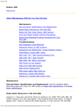
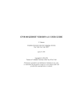
EGR Valve Service Requirements.
[Inquiry] What exactly is the EGR?. It
is specified in the service manual that
it must be checked / cleaned during
the 90,000km (~60000 mi) service.
[Response: Tom Irwin] The Exhaust
Gas Recirculation (EGR) valve is
located underneath the intake
manifold. If it gets plugged, you can
ruin an O2 sensor or get incorrect fuel
metering; basically the engine will run
like crap and use a lot of gas. To
service the EGR, it will be necessary
to remove the air induction apparatus
for clearance. Removing the throttle
body also helps and it is a good time
to clean it out as well. The same is
true for the IAC, Idle Air Contro
valve. Once you remove the EGR
valve, Take it to a bench and use a
vacuum pump to check operation and
hold open the diaphragm and valve,
or follow the procedure below. Spray carburetor cleaner through it. Also spray into
the tubes. A stiff wire might be useful if there is large debris or a plugged line. The
temperature sensor electrical connector should be de-oxidized and protected with
silicone dielectric grease.
EGR Valve Removal. [Procedure from Kevin] The EGR intake tube is held to the
intake manifold via 2-10mm bolts and a flange. The exhaust side is screwed into
the exhaust manifold with a 22mm acorn nut. Once the tubes are separated the
valve itself is held in a bracket via a large thin nut, best removed with a large
pliers. I found it took a good two-handed pull to break the 22mm acorn nuts free
(the nuts that attach the pipes to the valve). Your only option here is to use a
22mm open-ended wrench (unless you happen to have such a thing as a 22mm
crows-foot). Be real careful not to have the wrench slip and round off the nut. The
valve gets hot in operation, so the nuts tend to seize to the valve fittings and take
some persuasion to break loose. I sprayed PBlaster penetrating oil on the fittings
and let it sit for 20 minutes before trying. This is a classic knuckle-buster situation,
so it is a good idea to put on a pair of gloves. Access is limited with a big wrench
like this one, but once the nuts are started you will be able to turn them 1/6-turn
at a time till they are off. Once the nuts were off, I had to tap the inlet pipe with a
hammer to get it loose from the port on the end of the valve. The compression
fitting on the end of the pipe was kind of wedged in the port on the valve and did
notwant to come off at first. I could not get the outlet pipe off of the side of the
file:///C|/Users/Steve/Documents/Volvo%20FAQ%20Updated/EngineSensors.html[01/13/14 10:07:45 PM]
Engine Sensors
valve, so I took the valve off with this pipe still connected (disconnect the other
end of the pipe from the intake manifold first). The valve is held on a bracket with
a 25mm nut. I managed to get this off with a 1 inch AF open-ended wrench. Again,
it took some force to break it free, and access is limited so it was 1/6 or 1/4 turn
at a time to get the nut off. I had a difficult time getting the vacuum hose off the
valve. the rubber boot at the end of the hose was in very poor conditon (rubber
was breaking down and had taken on a tacky/gummy consistency) and was stuck
to the vacuum nipple on the valve. I assume this is due to the high temps that this
valve sees. I will be looking for a replacement as I do not think it is going to last
much longer.
EGR Valve Vacuum Checking/Cleaning. If you don't have a vacuum pump to
test operation, improvise: Insert an allen wrench or small screwdriver or other
suitable probe into the inlet port (threaded opening on the end of the valve) until it
contacts the valve seat. Keep one hand on this probe while maintaining a small
force to keep it in contact with the seat. Place vacuum nipple in mouth and suck!
You will feel the valve seat opening. The valve should hold open without any
additional suction. If the valve fails to open, or if the diaphragm leaks when you do
this, then the valve may need to be replaced. If you don't want to put engine parts
in your mouth, you can make a more hygienic mouthpiece from a couple of inches
of scrap vacuum hose. When I cleaned my valve, it had very little carbon/dirt in
the valve. Noticeable build up of carbon on end of the EGR discharge pipe, where it
connects to the intake manifold. Cleaned this up with a stiff wire and several
squirts of throttle-body cleaner
EGR Valve Reinstallation. I put a little anti-seize on the threads before
replacement (don't get any inside the ports though). I am hoping this will make it
easier to get the nuts off next time. Place the valve in its bracket. Hand tighten
clamping nut that holds it to the bracket. Start the threads on the two acorn nuts.
Attach the outlet pipe to the intake manifold and tighten the nuts there all the way.
Tighten the bracket clamping nut all the way. Tighten the two acorn nuts all the
way. Put a spot of silicone grease on the vacuum nipple and replace the vacuum
tube (again, I am hoping this will stop the rubber from gluing itself to the nipple.
Reconnect the temp sensor electrical connector.
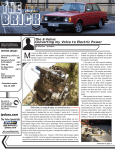
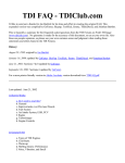
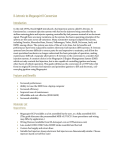
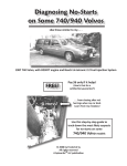
Pulsair Valve. [Tops from Tom F] Volvo introduced Pulsair system on B200/30A,
E, and K-engines and on the US '94-'95 B230FD engines. The Pulsed Secondary Air
injection system adds oxygen to the exhaust
manifold to
continue the
combustion of
unburned fuel in
the exhaust system
and provides
additional oxygen
for the catalytic
converter, thereby
lowering harmful
emissions. It is independent of the EGR system and
many cars have both. The pulsed secondary air injection solenoid or PAIR Solenoid
file:///C|/Users/Steve/Documents/Volvo%20FAQ%20Updated/EngineSensors.html[01/13/14 10:07:45 PM]
Engine Sensors
receives a signal from the ECU allowing the vacuum control valve to open via the
small diameter tube to the plastic shut-off valve. The solenoid is located on the left
strut support between the EGR Converter and the OBD box. The shut off valve is
located at the single end of the Y hose opposite the two pulsair valves. The PAIR
valve (Pulsair valve), with permission from the ECU, allows oxygen in every time
the exhaust valve closes, which causes an instance of negative pressure (the pulse)
and introduces oxygen into the manifold. No air pump required. The photo shows
the two Pulsar valves feeding the exhaust manifold and a vacuum control valve
which get its a signal from the PAIR solenoid to allow air from the air cleaner box
to pass through. If a valve fails, it can allow exhaust gas flow back, cooking the
rubber hose. The hose is connected to a vacuum operated shutoff valve connected
to the air cleaner. To test the pulsair valve, on a cold engine, place your hand over
the valves, near enough to verify that air is being taken in and exhaust gas is not
escaping. The action of the valve is a quick pulse corresponding to the opening and
closing of the exhaust valves. Also, pull the hoses and look down to see the valves:
they should be replaced if they are black from soot. They do wear out. [Tom] There
are two tubes that come off the manifold that go to the pulsair valves. Inside the
pulsair valve there is a stainless steel one-way flapper that allows clean, filtered air
into the exhaust using back pressure (every time an exhaust valve closes) and
prevents exhaust flow into the intake system. The first sign of a failed pulsair valve
is a cooked and cracked hose attached to the pulsair valves. In my case the plastic
valve with the small tube going to the pair valve did not fail. There are no disks at
the manifold or tubing: the one-way flapper "disks" are in the pulsair valves. I am
not sure what causes the failure of the valve but I think exhaust crud is a result of
the valve failure. The valve cannot be repaired.
Regina Air Temperature Sensor. The Regina fuel injection system uses air
pressure and temperature in the intake system to compute the air mass moving
into the engine. The temperature sensor is located in the intake hose or pipe. The
air mass passes through holes in the sensor and over a bulb which sends a
temperature signal from the incoming air charge to the ECU. Information from this
sensor is added to the pressure sensor information to calculate the air mass being
sent to the cylinders. The sensor is an NTC (Negative Temperature Coefficient)
thermister which means that resistance declines as the temperature increases. This
sensor helps the ECU to determine spark timing and air/fuel ratio. You can check
this resistance by connecting an ohmmeter between pins to read:
-20°C (4°F) 15K ohms
20°C (68°F) 2.5K ohms
100°C (212°F) 160 ohms
Use a heat gun to change temperature. Problems may occur in the sensor, the
connector, or the wiring leads.
Regina Manifold Air Pressure (MAP) Sensor. The Regina fuel injection system
uses air pressure and temperature in the intake system to compute the air mass
moving into the engine. The MAP pressure sensor is located on the driver's strut
tower support. It is connected to the intake manifold through a hose and takes a
reading of intake pressure. The sensor is piezo-electric and changes a voltage input
to an output signal proportional to manifold pressure. The system calibrates
file:///C|/Users/Steve/Documents/Volvo%20FAQ%20Updated/EngineSensors.html[01/13/14 10:07:45 PM]
Engine Sensors
atmospheric pressure when the engine is started and under full load conditions. To
test, turn ignition "on" and test the back of the sensor connector or the pins on the
back of the ECU connector (do not disconnect with the ignition "on"):
Connector A or pin 6 is ground
Connector C is the constant voltage input from pin 7 on the ECU and should
read 5 volts to ground
Connector B is the variable output signal from the pressure sensor to pin 11
on the ECU. Connect a hand vacuum pump to B or 11, apply vacuum, and
read the signal. Voltage should drop from 5 volts to a lower number. If it does
not drop, replace the sensor.
Problems may also occur in the sensor, the vacuum tube leading to it, the
connector, or the wiring leads.
OEM and Replacement Parts. ACDelco makes these sensors with replacement
parts as follows:
MAP sensor Volvo 3517892 ($146)= ACDELCO Part # 2131545 ($47) or
GM Part #12569240
Volvo Maintenance FAQ for 7xx/9xx/90 Cars
file:///C|/Users/Steve/Documents/Volvo%20FAQ%20Updated/EngineSensors.html[01/13/14 10:07:45 PM]