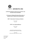
1
Investigation of Methods Currently Employed to Obtain Ice Thickness Distributions R.Hudson Beaufort Sea Ice Motion Programmes OERO 67113, 67114 Institute of Ocean Sciences Sidney, B.C. 018295 This work was supported by the Federal Panel on Energy R&D (PERD). Department of Supply and Services, Canada. DSS File #: 06SB.FP941-3-2205 INVESTIGATION OF METHODS CURRENTLY EMPLOYED TO OBTAIN ICE THICKNESS DISTRIBUTIONS For Or David Topham, Department of Fisheries and Oceans, Patricia Bay, Sidney, B.C. By Polar Tech Ltd, 676 Wain Road, RR1 Sidney, B.C. (604)656-9.131 Attn: Rick Hudson February 1984. POLAR TECH LTD Under Ice Profiling 1 SUMMARY Current techniques to profile ice thicknesses in a single ice pressure ridge and a ridged field are investigated. For the former, a combination of side-looking sonar profiles and ground-truth holes provide a cost-effective method of producing bottomside contour maps. As an added refinement, a diver might be used to evaluate the roughness of the ridge's surface in a s~bjective manner. To profile a larger ridged floe, a combination of stereoscopic aerial photography above and submarine sonar scanning below is recommended. The new ARCS untethered, unmanned vehicle looks promising. Keel depths and ridge orientations could be mapped effectively, but the technology is new, and the hidden costs still undefined. Direct methods of measuring ice thickness are briefly reviewed; there is little suitable for ridge profiling. POLAR TECH LTD Under Ice Profiling 2 INDEX ............................. • 2 . ..................... . • .4 Pro ject definition •• SURVEY OF A SINGLE RIDGE •. ...... • •5 Through-ice sonar .• 2.1 · . . 2.2 Diver survey •.•.••• . . . . .. . . . . .. •• .6• 7 ...... · .8 2.3 Local aerial survey •• SURVEY OF A LARGE ICE FIELD. .9 · ... .. . . . . Summary ••••••••••• 1• 2. 3. 3.1 3.2 3.3 3.4 ••••• Aerial survey •••• Submarine survey. Scanning Laser .•••••••• SLAR/ SAR ••••••••••••••• Direct sensing methods. . . . ... . • 11 ••• 1 2 .14 .1 4 .1 5 ·... REFERENCES •••••••••••••••••• . . .. . . . .. . . . . . . . .. • •• 1 6 3.5 4. ~ Sonar specifications Appendix I Appendix II: Submarine specifications POLAR TECH LTD Under Ice Profiling 3 1. PROJECT DEFINITION. Investigate and compare methods cu~rently employed to thickness distributions for the following situations. obtain ice 1. A detailed under-ice survey of a single isolated ice ridge. Compare a diver performed precision under-ice survey with side scan sonar techniques, give their expected accuracies with respect to vertical and horizontal positioning. Compare the above with any other practical techniques that have been used. 2. Under ice topography of a field of ice keels. Review available results of keel/ridge height statistics in the Beaufort Sea. Compare remote sensing methods (SLR, laser profilometer, stereo photos) utilising keel/ridge correlations to direct through ice sensing methods. POLAR TECH LTD Under Ice Profiling 4 2. SURVEY OF A SINGLE RIDGE. To profile a single pressure ridge in detail, no one technique suggests itself as having all the requirements necessary. Conventional expertise has centred around the use of side-looking sonars to obtain moderately accurate profiles of keels. Such a unit, together with recently developed signal processing, permits contour maps or 3-0 charts to be produced in near real-time. But the system cannot stand alone. Drill hales are necessary to ground truth the sonar data. In addition, there is, for this application, considerable interest in the surface texture of the keels. This can only be recorded by direct observation; TV cameras are a very inferior sUbstitute. However, it is the author's experience that de-briefing with divers, as to what was seen underwater, can also be misleading. Often, twa divers will describe the same feature in quite different terms. The solution therefore reduces to a compromise, depending an permissible cast and logistics. It is recommended that the program: 1. Use a narrow-beam, side looking sonar to achieve contour maps of the ridge's shape. Effective beam range is SOm, with a vertical resolution dependent an water depth (shallow water introduces multiple echo paths), generally ±~m or better (Offshore Survey Ltd). 2. If manpower is available, drill as many calibration hales as possible to check the sonar measurements. 3. If within budget, mobilise a diving team (out of Tuk) for a one day series of dives to carry out a rapid evaluation of the consolidation characteristics of the ridge, and to report back an any ather interesting features which the sonar has either missed or assumed to be something else. Comparative casts (see fallowing Sections) suggest that a diver survey would be mare than double that of the sonar system, and would take twice as lang. This in itself introduces the further uncertainty of relocating the floe each day, maintaining open dive hales, getting consistant flying weather, and the likelihood of either the helicopter or divers being pulled off the research job in favour ~f their an-going operations contracts. POLAR TECH LTD Under Ice Profiling 5 2.1 THROUGH- ICE SONAR There are several sonar systems on the market which offer a means to survey the underside of an ice sheet. For supplier specifications, please see Appendix I. Desirable characteristics are small sonar head (small ice hole ie. less time spent drilling) a stepping motor of sufficiently fine increment to assure adequate coverage both at the long-range end of each sweep, and between radii increments, and a pipe lowering system which is both light (for helicopter transport) and rigid (so as to minimise flexure and torque errors in the sonar reading). Mesotech Ltd of Vancouver produce sonar systems which operate in the Arctic. Their new Model 971 has a range of 100m and operates at 675 kHz. Cost is about $50,000. They do not rent. Offshore Survey Ltd of Vancouver have done a number of bottom-side profiles. They own and operate an Edo-Western system (which has a small diameter for fast surveys) and a Mesotech 952 sonar (360 kHz, 1.5 0 beamwidth, requiring a 12 inch diameter hole). They have also developed software for their Hewlett-Packard 9826 computer which converts the raw radial data and writes it to an XV plotter to display either as a contour map, cross-sectional chart, or 3-D profile. Effective range is about 50m, with resolutions of approximately +50cm •. horizontal and vertical Assuming a 'typical' ridge of about 150m in length, 3 holes on either side would suffice to profile the length. This could be achieved in a working day. An advantage of this system is that data plots are produced in near real time, allowing changes in research direction. Cost for such a project is: 1 operator at $375/d, 2 hole drillers at $350/d, plus helicopter at $1000/hr. Sub-total: $4,000. This cost includes the near-final plots of the floe. Mobilization from Vancouver will likely add $10,000 to this in freight, air fares and preparation of field equipment, but would be spread over the cost of the large ice field survey as well. POLAR TECH LTD Under Ice Profiling 6 2.2 DIVER SURVEY Candive in Vancouver are the acknowledged experts in this field, and have carried out numerous under-ice surveys. The survey would be done using a single diver plus or 2 technical support, assuming visual inspection duties only. Depths in excess of 20m make for long decompression times. Deep keels may have to be estimated subjectively, rather than lose valuable time. Diver would be in a in dry suit with an air hose to the surface. Party would likely muster out of Tuk, so no transport fees. A number of 'spot depths' could be recorded during a dive to cross-check the sonar data. Vertical accuracy would be +25cm. Horizontal correlation is rather diver dependent. The technique's advantage is that a substantially better evaluation of the ice's structure can be obtained from the observations of the divers. Diving costs are: Supervisor $460/d, diver $420/d, support equipment $250/d. For a 1 day survey (mobilising out of Tuk), excluding helicopter, likely cost is $1,130. If the survey were carried out exclusively by divers, rows and columns of stakes would be used to pinpoint a 10m x 10m grid on the underside of the ice. A diver would then hold a pressure sensitive depth gauge at each stake, and record the position and reading by voice phone with the. surface above. As mentioned earlier, this technique is considerably slower than the sonar method. Vertical resolution would be less than ±25cm. Horizontal error would be very diver dependent. POLAR TECH LTD Under Ice Profiling 7 2.3 LOCAL AERIAL SURVEY. A light-weight and relatively cheap alternative to the above would be to suspend a camera at sufficient height above the ground that stereoscopic photographs could be taken, but without the problems associated with aircraft. Given reasonably little wind, a meteorological balloon, filled by battle, could carry aloft a Hasselblad camera or equivalent. If a ground field of 300m was required, a height of much the same is all that is required. The balloon could be controlled by lines from 3 fishing rods. Photographs would be taken using a radio controlled trigger which is commercially available. The cost of materials is small, and a 2.25 square inch negative would permit adequate vertical resolution on the ground, especially as the pictures would carry reference paints set up by the field party. It might be argued that the technique is redundant, since if there is a helicopter on site, it may as well be used for the photographs. And if the large field survey is being dane aver the same period, there will, in all probability, be a 9 inch square camera being used. 80th are true. However, the technique is small, light and easily deployed, and may prove superior to the problems associated with getting an aircraft rated for photographic work, and setting it up. POLAR TECH LTD Under Ice Profiling 8 3. SURVEY OF A LARGE ICE FIELD. The survey of a multiyear ice floe having a typical diameter of 700m poses a different problem from that of the single ridge. Here, the emphasis is on statistical evaluation to establish the bottom roughness in general terms. Major ridge orientations, and keel depth distributions supercede the high resolution requirement, and a variety of less precise, ,more cost-effective systems are proposed. These are summarised as follows: 1. Aerial photography is the most often used technique, and permits good stereoscopic resolution to be achieved at reasonable cost. However, there is a limited data base allowing the correlation between sail height and keel depth of a ridge; this results in an error which may be very significant. More work needs to be done before this technique may be used alone. 2. Under ice survey using an unmanned submersible. To date, only one attempt has been made to use a tethered device to profile under ice. Its results are confidential, but rumoured to be poor. The current decline in offshore work has resulted in a leaser's market as regards subs, but all are still untried. The new ARCS, built for the Bedford Institute, N.S. by ISE of Vancouver, is due for trials in mid-March. It is an un tethered device specifically designed for under-ice work, and may prove to be a very powerful bottom-side ice profiler. 3. Laser profilometers have been used widely to establish ridge height distributions, but are unsuitable statistically for a small survey of this kind. A scanning laser is still at the discussion stage, and may not be operational for another 2 years. 4. SLAR and SAR are both unsuited for the single floe experiment, although some work suggests that SAR may be used to determine ridge width, and hence depth. A joint topside/bottomside survey is suggested, to correlate sail:keel ratio for the particular ice zone of interest. the The relationship between sail height and keel depth is poorly documented (Wadhams 1975, Wadhams & Horne 1977 and 1980, Hoare et al 1980a & b), and may be used to determine keels on a statistical basis only. It is not possible to determine individual ridge profiles with any degree of confidence. The probability distribution of ridges obtained from laser data in POLAR TECH LTD Under Ice Profiling 9 the Beaufort Sea is given as a function of ridge 1975) as: height (Wadhams P(h) dh = 7.727 exp (-1.603 h) dh P(h) dh is defined as the probability of encountering a ridge of height between hand h + dh per kilometer of the transect. The probability distribution of keels obtained in the near zane of the Beaufort Sea, using an upward looking sonar mounted an the sea bed (rather than a submarine) was calculated (Hoare et al 1980) as: N(D) dO = 2089 exp (-0.408 D) dO N(O) dO is the number of keels of draft between 0 and 0 + dO aver the entire season. If the ridge distribution function is normalised to unity at h = 0, and the keel distribution is normalised to unity at 0 = 0, thereby reducing the effects due to the differences in measuring instruments and their time:space relationship, the distributions became: P(h) dh = exp (-1.603 h) dh N(O) dO = exp (-0.408 D) dO The ratio of the exponential coefficients represents the calculated keel:sail ratio, which is 3.93. This is in agreement with many of the field observations based an the field profiling of a few ridges at a time, but represents the only known value based an a large statistical sample (Hoare et al 1980b). POLAR TECH LTD Under Ice Profiling 10 3.1 AERIAL SURVEY Widely used, and very quick. A slow flying aircraft is needed to carry out the precision survey, otherwise the plane's velocity will degrade the photographic negative at low altitude. The only charter aircraft operating in the north (out of Inuvik) which has an FAA approved camera hatch is a Rockwell Commander, which cruises at over 200 knots, and may not be suitable for low level precision reconnaisance. Cost is $600/hr. Okanagan Helicopters have a camera mount for a Bell 206, which may be more effective for small surveys. Stereoscopic processing of a typical floe, using a 10m grid, would be under $2000. This would include a 10 metre grid from which contours could be drawn, plus spot heights of any features of interest. Accuracy is dependent on there being a sea level reference to deduce zero, plus another known high point to remove tilt, and a known horizontal distance to specify scale. These require a ground visit to the floe. Using either the Bell 206 or the Commander, costs would be: camera operator at $300/d, plus mobilizat(on of $3000 (incl. freight), plus aircraft time of $1800 for 3 hours, plus helicopter time to ground-truth at $2000, plus interpretation at $2000. Total: $10,600. ·For little extra cost, a much larger field of data may be contoured. Vertical resolution on the sail is ±25cm; resolution on the keels is likely to be ±1m minimum, possible ±2m. POLAR TECH LTD Under Ice Profiling 11 3.2 SUBMARINE SURVEY Several vehicles are available, but to date no unmanned device has carried out an uner-ice survey successfully. Details of the various submersibles are included in Appendix 2. International Submarine Engineering Ltd (ISE) in Vancouver manufacture a variety of vehicles which could be used. Key issues are cost/day, bulk (which quickly increases the add-on operating costs), platform stability and range from point of entry. The smallest of the line is the DART, an unmanned sub, having a range of about 300m radius. It is small, will fit down a 24 inch hole and weighs about 150 lb in air. Survey speed is slow at 1.5 knots. Stability is acceptable. With clever ballasting, the centre of rotation could be lowered and the stability improved. There are DARTs at Victoria, Vancouver and Halifax. With the exception of the unit at DREP, the others are available with operators for rent. Costs vary from $1800 to 3000/d, depending on add-on equipment. SITDART is a bigger version of the DART, weighing 600 lb and offering a superior survey platform. HYDRA, HISUB and HYDROSTAR are all larger vessels, require large logistical back-up in the field. which would Offshore Survey's 'SEAL' is a much cheaper unit, but has no axial stability, so could not be used to sound upwards. All of the above are tethered via an umbilical line. based on power available to pull a longer line. Ranges vary Positioning is via two or more hydrophones lowered through the ice to establish an acoustic reference grid. Positioning accuracy is ±1m horizontal. The submarine would carry a pressure gauge to determine its true depth, enabling the ice's profile to be measured +50cm or better. Cost to operate the unit to survey a single 'standard' floe would result in some mobilization/testing time, likely $10,000, plus freight $3000, plus S61 support at $4000 for 1 day, plus operating costs of $6000 plus demobilization/processing of data at $3000. Total: $26,000. The Bedford Institute of Oceanography has commissioned ISE to build a long, torpedo-like submersible to operate untethered under ice, called ARCS. This is scheduled for sea trials in mid-March, 19B4, and permits extensive surveys (5 n.m. x 5 n.m.) to be carried out from a single entry point. POLAR TECH LTD Under Ice Profiling 12 The vehicle uses 4 hydrophones as references in a long base-line algorithm to navigate with an expected positional accuracy of ±2m in the horizontal mode, and ±0.5 in the vertical. Since it is untethered, all data is stored via an HCD 75 digital data acquisition system on a 3~ tape eck, having 36 Mbytes of capacity. An on-board doppler sonar also aids in dead-reckoning. The control system (billed as the second most sophisticated remote in the world) uses two 8086 microprocessors to control navigation, sonar I/O, acoustic telemetry and error detection, and an 8088 to trim the vehicle and store the data. Since the unit has such potential, and is already destined for a sister institute of IDS, Pat Bay, it is considered worthwhile to go into its design and capabilities in some detail, since they are not covered much in the Appendix. The basic unit, having 10 kW.hr of on-board power, will weigh about 3000 lb and be able to travel 50 n.m. at 5 knots. Additional battery packs may be added amidships, with each 10 kW.hr increasing the weight by another 1000 lb. Contact personnel at BID are John Brock (now an independent consultant, working on ARCS), Adam Kerr (Hd Hydrography) and Don Dinn (Engrg Mngr). At IDS, contacts are Terry Curran and Jim Gallaway. POLAR TECH LTD Under Ice Profiling 13 3.3 SCANNING LASER. The scanning laser has been used widely in the Arctic to profile ice top-sides, and most of its operational problems have been resolved. It does not lend itself to small scale surveys, however, since its footprint is very small. Many passes would be needed to obtain sufficient statistical data to profile the ice floe of interest, while the difficulties of flying a precise line accurate to a few metres would be impossible. The technique is included for completeness, and to draw attention to the interest currently being shown by a number of Federal agencies (CCRS, EMR Dept Surveys, 000) in the construction of a scanning laser. A DSS-funded contract to build such a device for the Hydrographic Survey has about a year to run before delivery of the system; however, it is possible that a smaller, lower powered system, using similar processing software and related hardware, could be used as the basis for another unit capable of profiling solid surfaces from the air. Contact person is Jack Gibson at CCRS. POLAR TECH LTD Under Ice Profiling 14 3.4 5LAR/5AR. Neither SLAR nor SAR have the resolution required for the current study, although the SAR imagery would be useful spacially for detail at the scale of interest. SAR can only resolve ridge widths. A paper by Inkster & Lawry (1980) claims that by measuring the width, the ridge height may be deduced; a thesis which requires further work. 3.5 DIRECT SENSING METHODS. There are currently three different techniques determine the thickness of sea ice from its topside manner. These are: being used to in a direct Electra-magnetic induction method. Peter Hoogensen of Geo-Physicon Calgary, has for a number of years used a modified shallow seismic investigation device. It is essentially two magnetic di-poles mounted 3 metres apart on a horizontal boom, which is carried in the field without difficulty. The read-out of the ice's thickness, based an induction paths, is not direct, and is subject to a consistant error which may be corrected. Ho~ever, the system integrates over the length of the boom, and is also susceptable to water enclosures in the ice. It is therefore not suitable for defining ridge bottomside profiles. ltd, Pulse radar. GSSI and more recently MP8 have developed pulsed . radar systems, usually in the 100 MHz band, to determine ice thickness. Like the magnetic di-pole system, it is sensitive to water layers, but if the antenna is mounted close to the ice, it measures a fairly small bottom surface. However, the equipment is expensive to rent, heavy, and heavily operator dependent. For these reasons, it is not considered suitable for ridge studies. Acoustic resonance method. This technique is currently being developed by a Sidney company, and holds promise as a small, cheap alternative which can measure ice thicknesses from 0.2m to 20m. Ho~ever, it tao is sensitive to water layering (if they are large) and may therefore give poor results in first year ridges. Multiyear should nat be a problem. A prototype is currently being tested, and may be available in late 1984. POLAR TECH LTD Under Ice Profiling 15 4 REFERENCES. Hoare R.D., Danielewicz B.W., Pilkington G.R., O'Rourke J.C., Wards R.D. "An upward-looking sonar system to profile ice keels for one year ", Proc. OCEANS 80, Seattle, Sept. 1980(a), p123. Hoare R.D., Oanielewicz B.W., Pilington G.R., O'Rourke J.C., "Seasonal pack ice characteristics in the shear zone of the Beaufort Sea, based on data from an upward looking sonic profiler." APOA Project 147, January 1980(b). Wadhams P., "Sea ice ridge statistics." Technical Report 36 of the Beaufort Sea Project, 1975. Wadhams P., Lowry R.T. "A joint topside-bottoms ide remote sensing experiment on Arctic sea ice." Proc. 4th Canadian Symp. on Remote Sensing, Quebec City, May 1977. Wadhams P., Lowry R.T. "An analysis of ice profiles obtained by submarine sonar in the Beaufort Sea." Jnl. Glac., v25, 93, p401, 1980. POLAR TECH LTD Under Ice Profiling 16 APPENDIX I Sonar profiling specifications MfSOlfCH MODEL 952 PRECISION PROFILING SONAR THE DREDG EMASTER'S SONAR' MESOTECH SYSTEMS LTD. MESOTECH MODEL 952 SINGLE AXIS BOTTOM SCAN PROFILING SONAR The Mesotech ModAl 952 Bottom Scan Profiling Sonar is a system which, from a single location records a profile of water depths along a particular line of bearing. By manually changing the orientation of the device, profiles along several lines of bearing can be obtained to provide detailed information of bottom conto'l.rs. The Model 952 is particularly useful in harbour and canal hathymetry, and during dredging operations. The ability to gather bottom profile information from a single point greatly speeds surveys and drastically reduces the amount of navigation required during a survey. ,The Model 952 Sonar Head transmits a narrow beam, high frequency acoustic pulse. The narrow beam is swept through a verticle plane, and the time for eacn pulse return is recorded, allowing calculation of the slant range to t!J.e bottom. The bottom profile is calculated from the slant range and angle data. The complete system ~~nsists of the Sonar Head, which is mounted underwater, and the Recorder Case. They are connected by ~ 100 foot cable. The Sonar Head contains the acoustic transducer, the stepping motor which sweeps the transducer, an inclinometer which senses rolling, the sonar transmitter and sonar receiver. The Recorder Case contains a microprocessor control system which reads the panel switches, drives the tra~sducer stepping motor, controls the sonar transmitter and receiver, reads the inclinometer, stores the data, and records the data on an X-Y plotter. The Model 952 can also operate as a precision recording depth sounder when the transducer is locked in the straight down position. 2 Specifications subject to change without notice. " ' -_ _ _ _ _ _ _ _ _ _ _ _ _ _ MESOTECH SYSTEMS LTD 2830 Hununglon PI I'on CoQulliam. S.C.. C~naoa V3C 4T3 relep/1one: 1604\464-8144 : relex: 04·353837 --~~_~~~----- MESOTECH MODEL 952 PROFILING SONAR BOTTOM SCAN METHOD OF OPERATrON NARROW BEAM TRANSDUCER IS SWEPT THROUGH A VERTICAL. PLANE ALONG A LINE OF BEARING o· (V£IIrTI CAt. FIGURE I •a • ............. "- . u -G., 011.'''· .,.,. 1.1" .... __ .........\ BOTTOM PROFILE AL.ONG THIS LINE IS RECORDED ON THE X-Y PLOTT!:R ".. ....................................-. .. , J. Ie· . • • - •• - . - " _ ••• I • - - - . - - • • • • • • . - MN FrGURE 2 PROFIL.ES ARE RECORDED AL.ONG SEVERAL. LINES OF BEARING TO MEASURE BOTTOM CONTOURS 8 3 FIGURE · I.-_ _ _3 _ _..;;.;........... _· ____ _ MESOTECH SYSTEMS LTD. 2830 HunllMqlon PI. _ _ _ _ _ _ _ _ _ _ _ _ _ _--1 ;.;.;;..;.~ Port CoQuil1am. B.C.. Canaaa V3C 4T3 Tareg/lOne: 1~)~-814' relex: 04·353637 MESOTECH SPECIFICATIONS - MODEL 952 OPERATING FREQUENCY: BEAM WIDTH: RANGE SCALES: 20, 40, 80, 160 m MINIMUM RANGE: 105m RANGE RESOLUTION: =.0.09 m RANGE ACCURACY: +0.5% SWEEP ANGLES (From Vertical): =.22.5 ° , =.45 ° , 67.5 ° , =.90 ° SWEEP OFFSETS: _60°, -30°, 0°, +30°, +60 0 (2 Axis only): ANGLE RESOLUTION: =.0.75° BEARING ANGLE (2 Axis only): ~900 selected in 1° steps SWEEP TIMES: 2.5 s (=.22.5°, 20 m) 44 s (=.90°, 160 m) Minimum: Maximum: SERIAL INTERFACE: POWER REQUIREMENTS: SIZES: 20 mA Current Loop 9600 Baud, Full Duplex Sonar Flotter Recorder Case: 115/230*V, 60 Hz, 500 VA 115/230 V, 60 Hz, 130 VA 2 Axis Sonar Head in Frame: 840 mm wide x 610 mm deep x 380 mm high (33"x24"x15") 248 mm x 298 mm x 1005 mm long (9.75"x11.75"x39.6") increase length to 1320 mm (52.2") TNEIGHT: Recorder Case (full): 1 Axis Sonar Head in Frame: 2 Axis Sonar Head in Frame: Head/Froc. Cable, 30 m (100 ft.): 46 32 40 26 1 Axis Sonar Head in Frame: kg kg kg kg (100 ( 70 ( 88 ( 57 lbs.) lbs.) lbs.) lbs.) *For 230 V operation of sonar, specify at time of order Specifications subject to change without notice. 4 1..-_ _ _ _ _ _ _ _ _ _ _ _ _ MESOTECH SYSTEMS LTD, 2830 Huntrngton PI Port CoQuI~~,_B,~:-. Can~~. '1Je 4T3 ......... _,_ ..-;,...----...;..;;,..~------ MESOTECH MODEL 952 BOTTOM SCAN PROFILING SONAR RECORDER CASE I'-----,~~- r ,I II I :i I I :1 ~ '-----~ , --- 1 , I I I 1 " ,, ~I d I I I I I ~, , 2.4" *' , ----~~~_ 15 " __L 5i '---~_- . _ -__ . -- - - - '-4ESOTECHSYSTE'-4SLTO 2830 HuntJn910nPI - - - - - - - - - - - ' Po" CoQu,Uam. B.C.. Canaaa V3C 4T3 TAI-c",,·t60414lW.a," T9lex: 04·353637 MESOTECH MODEL 952 DUAL AXIS BOTTOM SCAN PROFILING SONAR The Dual Axis version of the 952 Profiling Sonar is s~milar in operation to the Single Axis version. However, under processor control,using the 'integrated Bearing Drive, the Sonar Head can be oriented to a new bearing. The Transducer Bearing can be manually selected by operating the appropriate controls, or processor selected according to a programmable bearing step angle. The Dual Axis Model is capable of recording up to 8 separate profiles. The stored records can be plotted separately, in an isometric format, or in hydrographic chart format enabling a contour map to be drawn. The Dual Axis Sonar can plot these records on an HP 9872 X-Y Plotter,on a CRT Monitor (or electrosensitive graphics plotter to be interfaced with the monitor) or electrosensitive plotter, (A Model 1800 CRT Printer Driver is required). In the continuous sweep mode the CRT constantly displays the new profile when a search is being conducted. Specificationo subject to change without notice. 6 ' - - - - - - - - - - - - - - MESOTECH SYSTEMS LTD. 2830 Huntington PI _ _ _ _ _ _ _ _ _ _ _ _ _---1 I'oM CoQUltlam, S.C.. Can_ V3C 4T3 Tel8l)llone: (60414~.a'" T~I•• :·04.353637 MESOTECH ~- 73~ '" 0100 to\l"f\ (a.1!.7S·.... 20') IIOOIt - , 30$0 • 25+ • 7b (10' • 10" • 3") ",m '. " ...... -01- -MESOTECH MOOEI.. gS2 GENERAL ARRANGEMEHT 7 _ _ _ _ _ _ _- - - _ - - - - MESOTECH SYSTEMS LTD. 2830 Hunungton PI ...._ _ _ _ _ _ _ _ _ _ _ _ _ _ __ I'Ort CoQu,uam. B.C.. Canada "T:eIeIIIIQae: (604) 4~·8 t 44 V3C 4T3 Tal •• : 04·353637 MESOTECH Dredging Sonar Model 952-1 *Model 952-2 Option 1 Model 952-8 Single-Axis Sonar Head, c/w frame Single-Axis Processor, c/w power and interface cables Velocity of Sound Manual Entry Dual-Axis Sonar Head, c/w frame Note: new frame is 435 mm (16.5 in.)diam. Dual-Axis Processor, c/w power and interface cables Velocity of Sound Manual Entry *Specify 110V (standard) or 220V. Stepdown transformer supplied for 220V at No Charge at time of order. (Model 952-4 Mast Drive (for replacements only) Model 952-5 Gimbal Mount (Universal Deployment System) Model 952-6 Processor/Head Cable 30 m (100 ft) Model 352-9 Extension Cable. Specify length to 30 m (100 ft) max. Mil. Spec connectors fitted to ends Model 952-7 Case for Plotter and Processor Software 952 For HP 9825 Calculator HP 9872C 8 pen X-Y Plotter. (11x17 inch) paper NOTE: Plotter supplies are obtainable from Hewlett-Packard 280x430 mm CRT Monitor for 952 CRT Driver 230 mm (9 inch) CRT 110/220V, 50 Hz 625 l~es or 60 Hz/525 lines, 75Q NOTE: Customers may supply their own standard Video Display Monitor Specifications subject to change without notice. 8 ' - - - - - - - - - - - - - - - - ME50TECHSYSTEMS~TO.2830Huntlng1onPt.-------------....j F'on Coqu,lIam. a.c .. Can_ V3C 4T3 Tel_one: (604) 464·81« Telex: 04·353637 ACOUSTIC PROFILING SERVICES FEATURES • • • • Mapping of seafloor from stationary point. Seabed profiling from small hole in the ice. Ice ridge keel and multi-year ice floe profiling. Continuous monitoring of dredging progress from dredging platform. • Well suited for pipe trench inspections showing poSition of pipe in trench. • Ideal search tool for locating glory holes or wellheads. • Contour map generation from sonar data. Mesotech model 952 bottom profiling sonar. Inverted use of profiler for mapping underside of sea ice through hole. Sonar operation over stem of barge for monitoring of dredging progress. Contour map generated from under-ice profiles. Dual eqUipment set up on continuous dredging operation. System deployment from drill floor of rig for ship positioning. This unique acoustic profiling system has been adapted for a wide variety of a pplications by OFFSHORE SURVEY. • Dredge monitoring. • Positioning of drillships over wellheads and glory holes. • Search and location of subsea wellheads. • Profiling shape and depth of pipe trenches. • Position determination of pipe in pipe trench. • Positioning of subsea completion manifold for hookup to wellheads. • Contour mapping of seabed along pipe corridor. • Contour mapping of underside of sea ice. • Mapping and profiling of ice scours on seabed. • Monitoring progress of man-made islands and berms. • Delineation of grounded sea ice boundaries. Several cable and pipe mounted deployment systems have been developed to allow downward, horizontal, and upward looking operations. Data recording and processing capabilities provide a wide choice of visual presentations on either CRT displays or x- Y plotters. Ten sequential under-ice profiles with horizontal spacing of ten degrees. Offshore Survey and Positioning Services Ltd. 1974 Spicer Road. North Vancouver. B.C.. Canada V7H IA2 Telephone (604) 929-7961 Telex 04-352838 Fnnled In Canada by Mechacoior Offshore Survey Inc. Seattle. VYashington U.S.A. Colour Imaging Sonar SONAR Model 971 • • • • • • Ught weight miniature head Fits any vehicle or rig Mounts in any orientation Model 971-1 Sonar Head. Frequency: 675 kHz. Beamwidth: 1.7° horizontal, 60° vertical. Mechanical Resolution: 0.225° (step angle). Scanning: 360" continuous. or locked. Power Supply: 22-26 Vdc at 1 A max. Connector: Glenair GL 30G 4P-Be. 4 pin. Cable: 4000 m ( 13000 ft) max. length. Construction: Aluminum alloy 6061-T6. 300 Series stainless steel rigid PVC. polyacetal, epoxy Finish: Hard anodise. red. Temperature: Operating -100c to +40°C. Storage - 500C to + SO°e. Depth: 1000 m (3300 ft) max. working. Dimensions: 89 mm (3.5 in) diameter. 372 mm (14.64 in) long. Weight: In air 3.6 kg (8Ib). In water 1.4 kg (3 Ib). Model 971-1 Sonar Head 288.3mm (11.35 in) 372mm (14.64 In) Moundng 4 Holes 10-32 UNF x 13 mm (0.5 in) deep 89mm~_ (3.5in)-~~ "Note: Specifications subject to change without notice. Compact processor/controUer Comprehensive modes Simple, logical controls Model 971-2 Sonar Processor Display Modes: Sector, Polar, Perspective, Side-scan Unear, (and Test) Ranges: 0-5, 10, 20, 50, 100m. Scanning Arcs: 360° continuous, or 30°, 600, 120° sector. Sector Centre: 0°,30°, 60°, 90°, 120°, 150°,180°, 210°,240°,270°,300°,330°. Scanning Speed: Slow-l shot per step Medium-l shot per 2 steps Fast-l shot per 4 steps Side Scan: Transducer may be locked at any of the above sector centres. Data Resolution: 512 x 512 x 128 levels (colours). TIming Resolution: ± 16 fJS [== ± 12mm( -±-0.5 in) I. Video Output: RGB with composite sync. on all channels. Analogue IV pop into 75 Q. Cursor Control: Moveable to any point on display Readout: Range and Bearing to cursor are displayed on screen. Zoom: Area centred on the cursor is magnified x4 linear. Data Input: RS-232-C for user labels date, time (to be written on screen). Data Output: RS-232-C status £, errors Temperature: Operating -5°C to +40°C. Storage -200C to +60°C. Power Supply: 120/240 V, 60/50 Hz.2/1 A Dimensions: 483 mm (19 in) wide x 178 mm (7 in) high x 432 mm (17 in) deep. Weight: 14 kg (31 Ib). A Colour Imaging Sonar System A Model 971 System comprises one each: Model 971-1 Sonar Head. Model 971-2 Sonar Processor and Model 971-3 Sonar Display. The Sonar Head is an O-ring sealed pressure-proof aluminum cylinder, with a transmit-receive transducer at one end and a power/control/data connector at the other end Inside are telementry, microprocessor. transmitter, receiver, motor and power circuits. The Sonar Processor is a welded aluminum box. black and anodised, with white lettering. It controls all data aquisition modes, processes the telemetered data. and outputs 525 line (NTSC) or 625 line (PAL) RGBvideo. The Sonar Display is a very high resolution monitor with direct input to the Red. Green and Blue electron guns of the CRT (hence RGB). With an appropriate adaptor (NTSC or PAL) signals may be" stored on a video recorder. MESOTECH • • • Very high resolution monitor Direct RGB input Y4 million pixel display Model 971-2 Sonar Processor r-----'-''-'--.................L-----, I 22mm ~in.) 406~m (16 in) Model 971-3 Sonar Display Screen Size: 330 mm (13 in) diagonal Signal: RGB from Model 971-2 Input: 3 x BNC, 75 Q or high Z (loop through) Raster: 525 lines interlaced, 15,750 Hz or 625 lines interlaced, 15,625 Hz. Temperature: Operating -5°C to +40°e. Storage -20°C to +60°e. Power: 120/240 V, 60/50 Hz. 2/1A Dimensions: 374 mm (14.7 in) wide)( 351 mm (13.8 in) high x 409 mm (16.1) deep. Weight: 18 kg (40 Ib). Ordering Information Model 971-1 Sonar Head Model 971-2 Sonar Processor Model 971-3 Sonar Display Standard Accessories for: 971-1: Glenair GL20G 4S-D dummy, (fitted). Glenair GL20G 4S-F3 underwater connector with 1m (3ft) tail. Glenair GL20G 402 locking sleeve. 971-2: Power Cable MS to US 3 pin, or tail. Signal Cable MS to tail. Output Cables 3 x BNC male to BNC male. I/O Cable MS to D type. 971-3: Power Cable System: Operator's manual Service Manual MESOTECH SYSTEMS LTD. 2830 Huntington PI. Port Coquitlam, B.C .. Canada V3C 4T3 Telephone: (604) 464·8144 Telex: 04·353637 ... APPENDIX II Submarine specifications ARCS Autonomous Remote Controlled Submersible PRINCIPAL CHARACTERISTICS Dimensions . . . . . . . . . . . . . . . . . . . . . . Displacement . . . . . . . . . . . . . . . . . . . . Endurance ...................... . Speed . . . . . . . . . . . . . . . . . . . . . . . . . . . Maximum Operating Depth ........ . Construction . . . . . . . . . • . . . . . . . . . . Propulsion . . . . . . . . . . . . . . . . . . . . . . Supervisory Control Command and Telemetry Depth Control . . . . . . . . . . . . . . 11t!.:1ulng ConLL:ul ....•....... Autonomous Control . . . . . . . . . . . . . . Overall diameter - 25" Length - 14 - 16 feet 2150 - 2450 lbs. 20 hours 5 knots 1200 feet (3000 feet optional) Modular - Cannister 1/2 HP electric motor nickel cadmium battery (silver zinc option) Frequency diverse M-ary FSK Aco.ustic link Manual or Automatic M~nu~l or AuLom~~l~ Microprocessor Control for Auto Heading and Depth, and on board logic Navigation Compas s . . . . . . . . . . . . • . . . . . . . Depth . . . . . . . . . . . . . . . . . . . . . . Echo Sounder . . . . . . . . . . . . . . Obstacle Avoidance ........ Sonar . . . . . . . . . . . . . . . . . . . . . Positioning . . . . . . . . . . . . . . . . . . . . . . . . Capabilities ..........•......•.. Options . . . . . . . . . . . . . . . . . . . . . . . . . Sperry CL 11 gyroscope Pressure Sensor with digital readout at consol - xxxx.x feet or meters Mesotech or to Customer specification Amatek Straza CTFM 511 or customer specification Track positioning - Oceano Long Baselir system or to customer specification Track maintenance - Amatek Straza modified MRQ doppler sonar or to customer specification Controllable to a range of 5 mm Positioning to an accuracy of ± 5 mete] Capable of maintaining parallel tracks 25 meters apart Side Scan Sonar Acoustic Television and lighting Gyro Stabilization / ( ( ) \ I I I !i I -. TREe/DART DEPLOYHENT SYSTEH SPECIFICA'rION PRINCIPAL CHARACTERISTICS: - Drum Dimensions - Drum Capacity - 42" flange x 30" barrel x 34" wide. - 1,560 ft. of 1" diameter cable with 1" of free flange above the top layer. = 2,000 = 2,510 1bs. at 1bs. at a a - Drum Ratings - Full Drum Bare Drum to 126 fpm. to 100 fpm. - Drive - The winch is driven by means of a Vickers vane type motor through a totally enclosed inline planetary gear reducer that will be located inside- the drum barrel at one end of the winch. - Brake - An Ausco totally enclosed, spring set, pressure released disc type brake will be located between the hydraulic motor and planetary gear reducer. This brake will be automatically applied whenever the winch control is in the neutral position. Minimum holding capacity of the brake is 3,000 1bs. at the full drum. - Frame &: Drum - Fabricated aluminum. - Base - The winch and crane package will be mounted on a fabricated steel base suitable for bolting to the deck of a vessel. - Slip Rings - Provision will be made in one end of the winch dr~~ for the mounting of your slip ring assembly. Provision is also made in the drum barrel for the termination of your cable and the entry of the wires to connect to the slip ring assembly. - Crane - The winch and power package will be mounted on a Viva Model No.510 hydraulically actuated crane. This crane will be modified for use in a marine atmosphere by having the cylinder rods and pivot pins manufactured from stainless steel. The crane will be as shown in the enclosed Viva pamphlet and will be complete with one hydraulic extension and no manual extensions. TREC/DART DEPLOYMENT SYSTEM SPECIFICATION - Continued - Spooling - Power Unit - The winch drum will be complete with an automatic spooling mechanism. This will consist of two vertical, stainless steel rollers that are mounted in a fabricated aluminum carriage. The rollers are supported on sealed ball bearings and are mounted on stainless steel shafts. The carriage is supported on a stainless steel guide bar and is driven directly from the drum by means of a diamond screw, a hardened steel shuttle, and a stainless steel roller chain reduction. A clutch handwheel is located at one end of the diamond screw. When this is disengaged, the carriage may be moved manually to suit the position of the wire on the drum. The carriage is also equipped with a horizontal roller to support the cable when it is in the slack condition. - The winch and crane are powered by a 20 H.P., electro-hydraulic pumping unit that will be mounted so that it rotates with the crane and winch assembly. The electric motor to drive the pumps will be mounted on top of a fabricated aluminum reservoir that will be complete with all necessary inlet and outlet ports, a filler-breather cap, and a sightlevel gauge. Power requirements for the electric motor will be 220/440 volt, 3 phase, 60 cycle. The motor will have an explosion proof enclosure. The pump to power the winch will be 'an Eaton, axial piston type, variable displacement, over center pump. This will be connected in a closed loop circuit with hydraulic motor at the winch. This pump will be controlled by a set of Honeywell controls that will give infinitely variable speed control of the winch in either direction of operation and will have a central neutral position. The pump for the crane will be a Vickers, constant displacement, vane type pump that will be connected in an open loop circuit with the crane controls. Controls for the crane will consist of a 4 bank hydraulic valve package that will give separate control of each df the crane functions. All necessary components to complete both hydraulic systems are included and will be mounted and prepiped to provide a complete unit.