1
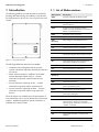
Planning Guidelines
SUNNY TRIPOWER 60
STP60-10-PL-en-10 | Version 1.0
ENGLISH
Legal Provisions
SMA Solar Technology AG
Legal Provisions
The information contained in this document is the property of SMA Solar Technology AG. Publishing
its content, either partially or in full, requires the written permission of SMA Solar Technology AG.
Any internal company copying of the document for the purposes of evaluating the product or its
correct implementation is allowed and does not require permission.
SMA Warranty
You can download the current warranty conditions from the Internet at www.SMA-Solar.com.
Trademarks
All trademarks are recognized, even if not explicitly identified as such. A lack of identification does
not mean that a product or symbol is not trademarked.
The BLUETOOTH® word mark and logos are registered trademarks owned by Bluetooth SIG, Inc.
and any use of these marks by SMA Solar Technology AG is under license.
Modbus® is a registered trademark of Schneider Electric and is licensed by the Modbus
Organization, Inc.
QR Code is a registered trademark of DENSO WAVE INCORPORATED.
Phillips® and Pozidriv® are registered trademarks of Phillips Screw Company.
Torx® is a registered trademark of Acument Global Technologies, Inc.
SMA Solar Technology AG
Sonnenallee 1
34266 Niestetal
Germany
Tel. +49 561 9522-0
Fax +49 561 9522-100
www.SMA.de
E-mail: [email protected]
© 2004 to 2015 SMA Solar Technology AG. All rights reserved.
2
STP60-10-PL-en-10
Planning Guidelines
SMA Solar Technology AG
Table of Contents
Table of Contents
1 Introduction. . . . . . . . . . . . . . . . . . . . . . . . . . . . . . . . . . . . . . . . . . 7
1.1 List of Abbreviations. . . . . . . . . . . . . . . . . . . . . . . . . . . . . . . . . . . . . . . 7
2 Inverter Overview . . . . . . . . . . . . . . . . . . . . . . . . . . . . . . . . . . . . 8
2.1 Type Label . . . . . . . . . . . . . . . . . . . . . . . . . . . . . . . . . . . . . . . . . . . . . . 8
2.2 Mechanical Overview of the Inverter . . . . . . . . . . . . . . . . . . . . . . . . . 9
2.3 Inverter Description . . . . . . . . . . . . . . . . . . . . . . . . . . . . . . . . . . . . . . . 9
2.3.1 System Overview . . . . . . . . . . . . . . . . . . . . . . . . . . . . . . . . . . . . . . . 10
2.3.2 Functional Safety . . . . . . . . . . . . . . . . . . . . . . . . . . . . . . . . . . . . . . . 12
2.3.3 Operating Modes . . . . . . . . . . . . . . . . . . . . . . . . . . . . . . . . . . . . . . 13
2.4 MPP Tracker and Power Reduction . . . . . . . . . . . . . . . . . . . . . . . . . . 14
2.4.1 MPP Tracker. . . . . . . . . . . . . . . . . . . . . . . . . . . . . . . . . . . . . . . . . . . 14
2.4.2 Power Reduction of the Inverter . . . . . . . . . . . . . . . . . . . . . . . . . . . . 14
2.4.3 Power Reference . . . . . . . . . . . . . . . . . . . . . . . . . . . . . . . . . . . . . . . 15
2.5 Grid Code . . . . . . . . . . . . . . . . . . . . . . . . . . . . . . . . . . . . . . . . . . . . . 16
2.5.1 Grid Protection Settings . . . . . . . . . . . . . . . . . . . . . . . . . . . . . . . . . . 16
2.6 Grid Support (Grid Management Services) . . . . . . . . . . . . . . . . . . . 17
2.6.1 Fault Ride Through . . . . . . . . . . . . . . . . . . . . . . . . . . . . . . . . . . . . . . 17
2.6.2 Reactive Power Management . . . . . . . . . . . . . . . . . . . . . . . . . . . . . 18
2.6.3 Active Power Management . . . . . . . . . . . . . . . . . . . . . . . . . . . . . . . 19
2.7 Functional Safety Settings . . . . . . . . . . . . . . . . . . . . . . . . . . . . . . . . . 19
3 System Planning – Mechanical . . . . . . . . . . . . . . . . . . . . . . . . . 19
3.1 Unpacking . . . . . . . . . . . . . . . . . . . . . . . . . . . . . . . . . . . . . . . . . . . . . 19
3.2 Installation . . . . . . . . . . . . . . . . . . . . . . . . . . . . . . . . . . . . . . . . . . . . . 20
3.2.1 Installation Conditions . . . . . . . . . . . . . . . . . . . . . . . . . . . . . . . . . . . 21
3.3 Mounting the Inverter . . . . . . . . . . . . . . . . . . . . . . . . . . . . . . . . . . . . 22
3.3.1 How to Position the Inverter . . . . . . . . . . . . . . . . . . . . . . . . . . . . . . . 23
3.3.2 Torque Specifications for Installation . . . . . . . . . . . . . . . . . . . . . . . . 23
3.4 Cable Specifications . . . . . . . . . . . . . . . . . . . . . . . . . . . . . . . . . . . . . 24
Planning Guidelines
STP60-10-PL-en-10
3
Table of Contents
SMA Solar Technology AG
4 System Planning – Electrical . . . . . . . . . . . . . . . . . . . . . . . . . . . 24
4.1 Introduction . . . . . . . . . . . . . . . . . . . . . . . . . . . . . . . . . . . . . . . . . . . . 24
4.2 DC Side . . . . . . . . . . . . . . . . . . . . . . . . . . . . . . . . . . . . . . . . . . . . . . . 24
4.2.1 Requirements for PV Connection . . . . . . . . . . . . . . . . . . . . . . . . . . . 24
4.2.1.1
Maximum Open-Circuit Voltage . . . . . . . . . . . . . . . . . . . . . . . . 25
4.2.1.2
MPP Voltage . . . . . . . . . . . . . . . . . . . . . . . . . . . . . . . . . . . . . . . 25
4.2.1.3
Short-Circuit Current . . . . . . . . . . . . . . . . . . . . . . . . . . . . . . . . . . 25
4.2.1.4
MPP Current . . . . . . . . . . . . . . . . . . . . . . . . . . . . . . . . . . . . . . . . 25
4.2.1.5
Resistance between PV Modules and Ground. . . . . . . . . . . . . . 26
4.2.1.6
Grounding . . . . . . . . . . . . . . . . . . . . . . . . . . . . . . . . . . . . . . . . . 26
4.2.1.7
Parallel Connection of PV Arrays . . . . . . . . . . . . . . . . . . . . . . . . 26
4.2.1.8
Dimensioning and Laying of PV Cables . . . . . . . . . . . . . . . . . . . 26
4.2.2 Determining Sizing Factor for PV Systems . . . . . . . . . . . . . . . . . . . . 27
4.2.3 Thin-Film PV Modules . . . . . . . . . . . . . . . . . . . . . . . . . . . . . . . . . . . . 27
4.2.4 Internal Overvoltage Protection . . . . . . . . . . . . . . . . . . . . . . . . . . . . 27
4.2.5 Thermal Management . . . . . . . . . . . . . . . . . . . . . . . . . . . . . . . . . . . 28
4.2.6 PV Simulation . . . . . . . . . . . . . . . . . . . . . . . . . . . . . . . . . . . . . . . . . . 28
4.2.7 PV Field Capacitance. . . . . . . . . . . . . . . . . . . . . . . . . . . . . . . . . . . . 28
4.3 Connection to the Low-Voltage Grid . . . . . . . . . . . . . . . . . . . . . . . . . 29
4.3.1 AC Connection Requirements . . . . . . . . . . . . . . . . . . . . . . . . . . . . . 29
4.3.2 AC Connection Protection . . . . . . . . . . . . . . . . . . . . . . . . . . . . . . . . 29
4.3.3 Grid Impedance. . . . . . . . . . . . . . . . . . . . . . . . . . . . . . . . . . . . . . . . 30
4.3.4 AC Cable Considerations . . . . . . . . . . . . . . . . . . . . . . . . . . . . . . . . 30
5 Communication and System Planning,
SMA Inverter Manager . . . . . . . . . . . . . . . . . . . . . . . . . . . . . . . 30
5.1 Ethernet Communication . . . . . . . . . . . . . . . . . . . . . . . . . . . . . . . . . . 30
5.1.1 System Overview . . . . . . . . . . . . . . . . . . . . . . . . . . . . . . . . . . . . . . . 30
5.1.2 SMA Inverter Manager . . . . . . . . . . . . . . . . . . . . . . . . . . . . . . . . . . 31
5.2 User Interfaces. . . . . . . . . . . . . . . . . . . . . . . . . . . . . . . . . . . . . . . . . . 32
5.3 I/O Box . . . . . . . . . . . . . . . . . . . . . . . . . . . . . . . . . . . . . . . . . . . . . . . 32
5.4 Weather Station . . . . . . . . . . . . . . . . . . . . . . . . . . . . . . . . . . . . . . . . 32
4
STP60-10-PL-en-10
Planning Guidelines
SMA Solar Technology AG
6 Technical Data . . . . . . . . . . . . . . . . . . . . . . . . . . . . . . . . . . . . . . 33
6.1
6.2
6.3
6.4
6.5
6.6
Technical Data. . . . . . . . . . . . . . . . . . . . . . . . . . . . . . . . . . . . . . . . . .
Thresholds for the Reduction of the Design Factors . . . . . . . . . . . . . .
Standards . . . . . . . . . . . . . . . . . . . . . . . . . . . . . . . . . . . . . . . . . . . . .
Specifications for Grid Protection . . . . . . . . . . . . . . . . . . . . . . . . . . .
Technical Data of the Communication Interface . . . . . . . . . . . . . . . .
Ethernet Connections . . . . . . . . . . . . . . . . . . . . . . . . . . . . . . . . . . . . .
33
34
35
36
37
38
6.6.1 Network Topology. . . . . . . . . . . . . . . . . . . . . . . . . . . . . . . . . . . . . . 38
Planning Guidelines
STP60-10-PL-en-10
5
6
SMA Solar Technology AG
STP60-10-PL-en-10
Planning Guidelines
SMA Solar Technology AG
1 Introduction
The planning guidelines provide information required for
planning and dimensioning an installation. They describe
the requirements for the use of a Sunny Tripower 60 in PV
systems.
Figure 1.1 Sunny Tripower 60
The following additional materials are available:
• Installation manual (supplied with the inverter) contains information required to install and commission
the inverter.
• Quick reference guide for installation of the SMA
Inverter Manager and the I/O box - contains
information required to install the SMA Inverter
Manager.
• Service manual for replacing the fan – contains
information required to replace a defective fan.
• Service manual for replacing the SPDs – contains
information required to replace surge protection
devices.
These documents are available in the download area at
www.SMA-Solar.com or can be obtained from the inverter
supplier. Additional application-specific information is
available at the same location.
Planning Guidelines
1 Introduction
1.1 List of Abbreviations
Abbreviation
Description
ANSI
American National Standards Institute
AWG
American Wire Gauge
cat5e
Category 5 twisted pair cable (enhanced) for
data transmission
DHCP
Dynamic Host Configuration Protocol –
enables automatic assignment of the network
address via the DHCP server
DNO
Distribution network operator
DSL
Digital Subscriber Line
EMC
(directive)
Electromagnetic compatibility directive
ESD
Electrostatic discharge
FCC
Federal Communications Commission
FRT
Fault Ride Through
GSM
Global System for Mobile Communications
(standard for digital cellular mobile network)
HDD
Hard Disk Drive
IEC
International Electrotechnical Commission –
international standards organization
IT
Isolated Terra
LCS
Local Commissioning and Service
LED
Light-emitting diode
LVD
(Directive)
Low voltage directive
MCB
Circuit breaker
MPP
Maximum Power Point
MPPT
Maximum Power Point Tracking determines the
point of optimum PV power
NFPA
National Fire Protection Association
P
P is the symbol for active power and is
measured in Watts (W).
PCB
Printed circuit board
PCC
Point of Common Coupling - Point of
interconnection. The point on the public
electricity grid to which other customers are, or
could be, connected.
PE
Protective Grounding
PELV
Protected Extra-Low Voltage
PLA
Power Level Adjustment = Output power
limitation
Pnom
Power [W], Nominal active power
STP60-10-PL-en-10
7
2 Inverter Overview
SMA Solar Technology AG
Abbreviation
Description
2 Inverter Overview
POC
Connection point - The point at which the PV
system is connected to the transmission line.
2.1 Type Label
PSTC
Power [W], Standard Test Conditions
PV
Photovoltaic, photovoltaic cells
RCD
Residual-Current Device
RCMU
Residual Current Monitoring Unit
RISO
Insulation resistance
ROCOF
Rate of Change of Frequency
Q
Q is the symbol for reactive power and is
measured in reactive volt-amperes (VAr).
S
S is the symbol for apparent power and is
measured in volt-amperes (VA).
STC
Standard Test Conditions
SW
Software
THD
Total Harmonic Distortion
TN-S
AC grid with separated grounding and neutral
conductors
TN-C
AC grid with combined grounding and neutral
conductors
TN-C-S
Terra Neutral - Combined - Separate. AC
Network
TT
AC grid with separation between operational
ground of the generator and ground of the
load system
Figure 2.1 Sunny Tripower 60 type label
Table 1.1: Abbreviations
8
STP60-10-PL-en-10
Planning Guidelines
SMA Solar Technology AG
2 Inverter Overview
2.2 Mechanical Overview of the
Inverter
1
Cover for installation area
2
Front cover
3
Die-cast aluminum heat sink
4
Wall mounting bracket
5
Display (read-only)
6
PV load-break switch
7
Fan
Figure 2.3: Mechanical overview of the inverter
2.3 Inverter Description
Inverter properties:
• IP65 enclosure/Type 3R
Figure 2.2 Sunny Tripower 60-US type label
The type label on the side of the inverter shows:
• Inverter type
• Important technical data
• Serial number, located under the bar code, for inverter
identification
• PV load-break switch
• Grid management function
• Transformerless
• Three-phase
• 3-level topology with high performance capacity
• Integrated residual current monitoring unit
• Insulation test functionality
• Extended fault-ride through functions (to support
reliable power generation during system incidents) depending on the inverter parameterization
• Complies with the requirements for a wide range of
national grids
• Adapted to local requirements and conditions via grid
code setting
Planning Guidelines
STP60-10-PL-en-10
9
2 Inverter Overview
SMA Solar Technology AG
2.3.1 System Overview
The STP 60 system with a Sunny Tripower 60 uses the
advantages of both string inverters and central inverters,
making it highly applicable in many commercial and utility
scale plants.
The STP 60 system consists of the Sunny Tripower 60, a DC
String-Combiner and the SMA Inverter Manager.
The communication network of a STP 60 system is divided
into two Ethernet networks: system network and inverter
network. The system network is the communication interface
to the STP 60 system and may be used by several SMA
Inverter Managers as well as other IT devices, while the
inverter network is solely used for the inverters. The system
network must have a DHCP server (router) assigned to the
inverter as the SMA Inverter Manager requires automatic IP
assignment. It is recommended to use professional routers
and network switches. The SMA Inverter Manager allows
for:
• Control of up to 42 SMA inverters of type Sunny
Tripower 60
• Single point of access for each 2.5 MVA system
(maximum value) for simple system network
deployment.
• Easy commissioning and maintenance of the system
using the Local Commissioning and Service (LCS) tool
• Safe data upload to data warehouse services and
control of all local requirements and settings from the
DNO
• Open source Modbus TCP communication protocol
using SunSpec Alliance profile via Ethernet both for
monitoring and control, making it easy to integrate in
SCADA systems, for example
• Grid management interface through the optional I/O
box for PLA and reactive power commands
• Easy integration of metrological data using an RS485
SunSpec Alliance compliant weather station
10
STP60-10-PL-en-10
Planning Guidelines
SMA Solar Technology AG
2 Inverter Overview
1
PV STRINGS
6
LCS TOOL
2
DC COMBINER
3
STP 60-10
1
5
ROUTER
12
4
PV STRINGS
INVERTERMANAGER
DC COMBINER
STP 60-10
7
PORTAL
8
SCADA
SYSTEM
9
WEATHER
STATION
1
12
10
I/O BOX
11
GRID
MANAGEMENT
PV STRINGS
DC COMBINER
1
STP 60-10
12
TRANSFORMER
STATION
12
DC
AC
1
Strings
2
PV array junction box
3
Sunny Tripower 60
4
SMA Inverter Manager
5
Router
6
LCS tool
7
Portal upload
8
SCADA system
9
Weather station
10
I/O box
11
Grid management
12
Transformer station
ETHERNET
RS485
Figure 2.4: System overview
Planning Guidelines
STP60-10-PL-en-10
11
2 Inverter Overview
Figure 2.5: Overview of the installation area
PELV (safe to touch)
2
Device grounding
7
Ethernet interface x 2
8
RS485 interface (not in use)
Live Parts
1
AC terminals
5
PV terminals
Other
3
AC overvoltage protection (SPDs)
4
DC overvoltage protection (SPDs)
6
PV load-break switch
12
STP60-10-PL-en-10
SMA Solar Technology AG
2.3.2 Functional Safety
The inverter was developed for international use and has an
electronic circuit for functional safety complying with a wide
range of national requirements (see Section 2.5, page 16).
Single-Fault Immunity
The functional safety circuit has a fully redundant integrated
single-fault detection. If a fault occurs, the inverter
disconnects from the grid immediately. The method is active
and covers all circuitry within the residual current
monitoring, both for continuous levels and sudden changes.
In order to guarantee safe operation, all functional safety
circuits are checked during the inverter start-up phase. If a
circuit fails more than once out of three times during the
self-test, the inverter switches to "fail-safe" mode. If the
measured grid voltages, power frequencies, or residual
currents during normal operation differ too much between
the two independent circuits, the inverter interrupts grid
feed-in and repeats the self-test. The functional safety circuits
are always activated and cannot be deactivated.
Planning Guidelines
SMA Solar Technology AG
Insulation
During the self-test, the inverter has an isolation measuring
system that detects whether the isolation in the PV system is
above the required value. This is done before the inverter
starts to feed into the grid. During grid connection, the
inverter measures the continuous residual current in the
system. If this value is exceeded more than four times within
24 hours, the inverter stops operating due to possible safety
hazards in the PV system.
2 Inverter Overview
2.3.3 Operating Modes
The inverter has five operating modes, indicated by LEDs.
Status
LEDs
Off grid
Green
Connecting
Green
On grid
Green
Red
Red
INFORMATION
Depending on the required local connection
conditions, a minimum insulation resistance between
ground and PV is specified. A typical value is 82 kΩ.
Self-test
The insulation resistance between the PV arrays and ground
is also tested during the self-test. The inverter does not feed
into the grid if the resistance is too low. After ten minutes, the
inverter makes a new attempt to feed into grid.
Red
Internal inverter
event
Green
Fail safe
Green
Red
Red
Table 2.1
Differential current
The residual current is continuously monitored. The inverter
interrupts grid feed-in in the following cases:
• The cycle root-mean-square value of the residual
current violates the disconnection settings for more than
the duration of the "clearance time", or
• A sudden jump in the residual current is detected
Grid Monitoring
If the inverter feeds into the grid, the following grid
parameters are monitored:
Off grid (standby) (LEDs are off)
#0-51
When no power has been fed into the AC grid for more
than 10 minutes, the inverter disconnects from the grid and
shuts down. User and communication interfaces remain
powered for communication purposes.
Connecting (green LED is flashing)
#52-53
• DC content of grid current
The inverter starts up when the PV input voltage reaches the
minimum DC feed-in voltage. The inverter performs a series
of internal self-tests, including measurement of the resistance
between the PV array and ground. Meanwhile, it also
monitors the grid parameters. When the grid parameters
are within the specifications for the required amount of time
(depends on grid code), the inverter starts feeding into the
AC grid.
On grid (green LED is glowing)
• Residual current by means of RCMU
#60
• Grid voltage magnitude (instantaneous value and 10
minute average)
• Grid voltage and power frequency
• Grid failure (islanding detection):
– Three-phase grid failure detection
– Rate of change of frequency (ROCOF)
– Frequency shift.
The inverter interrupts grid feed-in if one of the parameters
violates the grid code settings.
The inverter is connected to the AC grid and feeds into the
grid. The inverter disconnects from the grid in the following
cases:
• It detects abnormal grid conditions (depending on the
grid code), or an internal event occurs.
• PV power is insufficient (no power is fed into the grid for
ten minutes).
Planning Guidelines
STP60-10-PL-en-10
13
2 Inverter Overview
SMA Solar Technology AG
The inverter switches to connection mode or operating
mode "off-grid mode".
2.4 MPP Tracker and Power
Reduction
Internal inverter event (green LED is flashing)
2.4.1 MPP Tracker
#54
The inverter is waiting for an internal condition to be within
the thresholds again (for example, when excessive
temperature decreases) before it reconnects to the grid.
Fail safe (red LED is flashing)
#70
If the inverter detects an error in its circuits during the self-test
(in connecting mode) or during operation, the inverter
switches to fail safe mode and disconnects from the grid.
The inverter will remain in "fail-safe" mode until PV power
has been absent for ten minutes or the inverter has been shut
down completely (AC+PV).
The Maximum Power Point Tracker (MPPT) is an algorithm
which is constantly trying to maximize the output power of
the PV array. The algorithm updates the PV voltage fast
enough to follow rapid changes in solar irradiation. The
MPPT will find the maximum power point while the PV
voltage is within the specified MPP voltage range. At
voltages below the minimum MPP voltage of the inverter, the
MPPT moves away from the maximum power point (see
figure 2.6) in order to maintain sufficient DC voltage to
generate the required AC grid voltage.
Figure 2.6 MPPT behavior at low MPP voltage
INFORMATION
Since the Sunny Tripower 60 has no step-up
converter, the minimum MPP voltage varies as a
function of the current AC grid voltage.
2.4.2 Power Reduction of the Inverter
In certain situations, the MPPT purposely moves away from
the maximum power point. This behavior is called "power
reduction" and is a means of protecting the inverter against
overload or a reduction of output power in order to support
the grid. Reactive power (supporting the grid) has priority
when the derate function is reducing the AC output power,
meaning that first active power is reduced to zero where
after reactive power is reduced. The STP 60 system reduces
its power under the following circumstances:
• Exceeding the maximum nominal AC power
• Internal overtemperature
• Grid overvoltage
• Excessive power frequency
14
STP60-10-PL-en-10
Planning Guidelines
SMA Solar Technology AG
2 Inverter Overview
defined threshold (ten-minute average value (U2)), the
inverter interrupts grid feed-in in order to maintain grid
quality and protect other devices connected to the grid.
• Output power limitation by settings or external
command (PLA)
Each Sunny Tripower 60 inverter limits the AC output power
according to the current power reference which
corresponds to the lowest of the following values:
• Maximum nominal AC power (60 kVA)
• Fixed active/reactive power threshold set by the grid
code file
• Active or reactive power reference from the SMA
Inverter Manager
• Power limitation of the internal temperature-dependent
power reduction. Power reduction due to temperature
is a sign of excessive ambient temperature, a dirty heat
sink, a blocked fan or similar. Information on
maintenance can be found in the installation manual of
the Sunny Tripower 60. The values shown in table 2.7
are measured at nominal conditions cos(φ) = 1
U1
Fixed
U2
Disconnection limit
Figure 2.8 Grid voltage above threshold, defined by DNO
Power reduction - grid overfrequency
The output power is reduced as a variable of the power
frequency. There are two methods for reducing the output
power: ramp and hysteresis. The grid code setting
determines which method is implemented in a specific
installation.
Primary frequency control – ramp method
See figure 2.9.
Figure 2.7 Power reduction as a function of the ambient temperature
INFORMATION
The inverter can use the entire permissible DC voltage
range up to 1,000 V for power reduction. It is not
restricted to the MPP voltage range.
The inverter reduces output power if the grid frequency
exceeds f1. Reduction occurs at a preconfigured rate which
is the ramp (R) shown in figure 2.9. When the frequency
reaches f2, the inverter disconnects from grid. When the
frequency decreases below f2, the inverter is reconnected
to the grid and increases power at the same rate as for the
reduction.
2.4.3 Power Reference
The power reference for the individual inverters of type
Sunny Tripower 60 will be generated by the SMA Inverter
Manager based on the following functions. They are all
stored in the SMA Inverter Manager and thus calculated on
system level.
• Grid Overvoltage
When the grid voltage exceeds the threshold U1
specified by the DNO, the inverter derates the output
power. If the grid voltage increases and exceeds the
Figure 2.9 Primary frequency control – ramp method
Planning Guidelines
STP60-10-PL-en-10
15
2 Inverter Overview
Frequency Stability - (Active Power Reduction in case
of Overfrequency) - Hysteresis
See figure 2.10.
To support power frequency stabilization, the inverter
reduces its output power if the power frequency exceeds f1.
Reduction occurs at a preconfigured rate which is ramp (R)
shown in figure 2.10. The reduced output power limit is
maintained until the grid frequency has decreased to f2.
When the power frequency has decreased to f2, the
inverter output power increases again following a time
ramp T. If the power frequency continues to increase, the
inverter disconnects at f3. When the frequency decreases
below f2, the inverter is reconnected to the grid and
increases power at the same rate as for the reduction.
SMA Solar Technology AG
2.5.1 Grid Protection Settings
The grid protection settings are stored in each inverter. They
ensure protection of the grid in case of certain grid events
regardless of the connection to the SMA Inverter Manager.
The inverter continuously monitors the following grid values
and compares them to the disconnection values specified in
the grid code. Example:
• Voltage disconnection
• Frequency disconnection
• Reconnection
• Grid failure
Voltage and frequency disconnection
The cycle root-mean-square values of the grid voltage are
compared with two lower and two upper disconnection
settings, for example overvoltage (level 1). If the
root-mean-square values violate the disconnection settings
for more than the duration of "clearance time", the inverter
interrupts grid feed-in.
Figure 2.10 Primary frequency control – hysteresis method
2.5 Grid Code
The STP 60 grid code file contains settings that determine
both the behavior of the single inverter and the entire
system. The grid code file is divided into two main sections:
• Protection settings
• Grid support (grid management services)
The LCS tool used for commissioning the inverter is
equipped with a range of standard grid codes to meet
national requirements. Changing these standard grid code
parameters requires a customer-specific grid code file
supplied by SMA Solar Technology AG. Refer to Section
2.7, page 19 on how to apply for customer-specific grid
code parameters.
Figure 2.11 Overvoltage and undervoltage disconnection
Reconnection
During commissioning or when the inverter has
disconnected from grid due to for example overvoltage or
frequency, the reconnection values determine under which
grid conditions the inverter can reconnect to the grid and
start feed-in.
INFORMATION
Obtain approval from the local distribution network
operator (DNO) before connecting the inverter to the
grid.
16
STP60-10-PL-en-10
Planning Guidelines
SMA Solar Technology AG
Grid Failure Disconnection (Stand-Alone Mode)
Grid failure is detected by three different algorithms:
• Three-phase voltage monitoring (the inverter controls
the current of each individual line conductor). The cycle
root-mean-square values of the grid voltages of the line
conductors are compared with a lower or an upper
disconnection setting. If the root-mean-square values
violate the disconnection settings for more than the
duration of the "clearance time", the inverters interrupts
grid feed-in.
2 Inverter Overview
• to increase the energy delivered to the AC grid.
There are four different behaviors to select from:
• Zero current
• Reactive power only
• Active current only
• Full current – reactive power priority
How FRT Works
Figure 2.12 shows the requirements that must be followed
by FRT. The example is for German medium-voltage grids.
• Rate of change of frequency (ROCOF). The ROCOF
values (positive or negative) are compared to the
disconnection settings. The inverter disconnects from
the grid when the thresholds are violated.
• Frequency shift. The inverter continuously tries to
extend the power frequency a bit, but the stability of the
grid prevents this from happening.
In a grid failure situation, the stability of the grid is no longer
present, and this makes it possible to change the frequency.
As the frequency deviates from the operating frequency of
the cable, the inverter disconnects from the grid and
interrupts grid feed-in. If the inverter stops grid-feed in due to
power frequency or grid voltage (not due to a grid failure
caused by phase imbalance), and if the frequency or
voltage is restored within a short time (short interruption
time), the inverter can reconnect when the grid parameters
have been within their limits for the specified time (reconnect
time). Otherwise, the inverter returns to the normal
connection sequence.
2.6 Grid Support (Grid
Management Services)
The grid management services are comprised in two main
categories:
• "Fault Ride Through" function (FRT).
• Reactive and active power management
2.6.1 Fault Ride Through
The grid voltage usually has a smooth characteristic curve
but occasionally the voltage drops or disappears for several
milliseconds. This is often due to short circuits in overhead
power lines or caused by operation of switching devices or
similar in the high-voltage grid. In such cases, the inverter
can continue to supply power to the grid using fault ride
through (FRT) function. Continuous electricity supply to the
grid is essential:
Above line 1 For voltages above line 1, the inverter
must not under any circumstances be
disconnected from the grid during FRT.
Range A
The inverter must not disconnect from
grid for voltages below line 1 and left of
line 2. In some cases, the DNO allows
short-term disconnection. The inverter
must then be back on the grid after two
seconds.
Range B
To the right of line 2, a short-term
disconnection from grid is always
permitted. The reconnection time and
power gradient can be negotiated with
the DNO.
Below line 3 Below line 3, grid connection is no longer
required.
Figure 2.12 Example for Germany
In case of a short-term disconnection from the grid:
• The inverter must be back on the grid after 2 seconds
• The active power must be ramped back at a maximum
rate of 10% of nominal power per second
• to help prevent a complete voltage blackout and
stabilize the grid voltage.
Planning Guidelines
STP60-10-PL-en-10
17
2 Inverter Overview
SMA Solar Technology AG
Active Power Management
The inverter can support the local grid by either static or
dynamic limitation of the system output power. The different
control methods are:
• Fixed Pref – maximum active power limitation
• Power Level Adjustment (PLA) – remotely controlled
maximum active power limitation (requires I/O box)
2.6.2 Reactive Power Management
The inverter can support the local grid by feeding in reactive
power. The different control methods are:
Q(V)
Grid feed-in of reactive power as a function of
the grid voltage.
Q(P)
Grid feed-in of reactive power as a function of
the active output power.
Q(S)
Grid feed-in of reactive power as a function of
the apparent output power.
PF(P)
Power factor as a function of active output
power.
Figure 2.13 Q(V) setpoint curves – reactive power
PFext
Power factor according to external signal either
via Modbus or the external I/O box (RS485).
Qext
Grid feed-in of reactive power according to
external signal either via Modbus or the external
I/O box (RS485).
When the grid voltage is below the nominal value, the
inverter is configured to feed-in over-excited reactive power
in order to increase the grid voltage back to the nominal
value. When the grid voltage is above the nominal value,
the inverter feeds in underexcited reactive power to
decrease grid voltage and thus supports the grid by
maintaining a more stable voltage.
Table 2.2 Reactive power management, control methods
Qext. and PFext
INFORMATION
Only one method can be used at the same time. A
mode selector determines which method is to be
activated.
With the setpoint curve Q(V), the inverter controls reactive
power as a function of the grid voltage V. The values for the
setpoint curve are determined by the local utility company
and must be obtained from them (see figure 2.13 ).
18
STP60-10-PL-en-10
Remote control of a system's active power and reactive
power grid feed-in can be handled with I/O box via RS485
or via an external signal via Modbus.
I/O box
The I/O box monitors the relay state of the ripple control
receiver (supplied by the DNO) and transmits the state to
the SMA Inverter Manager via RS485. The SMA Inverter
Manager translates the relay state into the corresponding
PLA value (max. system output power) based on the grid
code configuration.
Planning Guidelines
SMA Solar Technology AG
1
Ripple control receiver
2
I/O box
3
SMA Inverter Manager
4
Sunny Tripower 60
Figure 2.14
External signal via Modbus
The Modbus SunSpec control profile can be used to control
the amount of reactive power feed-in by the system.
2.6.3 Active Power Management
Apparent power management
The inverter can support the local grid by setting a maximum
value for the apparent power.
• Fixed Sref – threshold for the maximum apparent
power
Fallback
The inverters in the inverter network are controlled by a Qref
and Pref from the SMA Inverter Manager. If the connection
to the SMA Inverter Manager is interrupted, the inverter
disconnects from grid within ten seconds. If the connection
is re-established within two seconds, the inverter will not
disconnect from grid. As soon as the connection is
re-established, the inverter reconnects to grid.
2.7 Functional Safety Settings
The inverter is designed for international use and it can
handle a wide range of requirements related to functional
safety and grid behavior. Parameters for functional safety
are predefined and do not require any alteration during
installation. However, some grid code parameters may
Planning Guidelines
3 System Planning – Mechanical
require alterations during installation to allow optimization
of the local grid. Please contact SMA Solar Technology AG
to obtain a customer-specific grid code.
3 System Planning –
Mechanical
The aim of this section is to provide general information for
planning the mechanical installation of the Sunny Tripower
60, including mounting and cable specifications.
3.1 Unpacking
Content:
• Inverter
• Wall mounting bracket
• Accessories bag containing:
– 6 wall screw anchors, 8 x 50 mm
– 6 mounting screws, 6 x 60 mm
– 1 M25 cable gland with sealing grommet for
Ethernet cables
– 1 grounding bolt, 6 x 12 mm
– For STP 60-10-US additionally included: 2 x cable
channel with conduit bracket (2")
• Installation manual (multilingual)
• Quick reference guide for installation (poster)
STP60-10-PL-en-10
19
3 System Planning – Mechanical
3.2 Installation
Figure 3.1 Avoid constant contact with water
SMA Solar Technology AG
is permitted.
Figure 3.7 Prevent dust and ammonia gases
INFORMATION
When selecting the installation site, ensure that the
product and warning labels remain visible on the
visible. For details, refer to Section 6, page 33.
Figure 3.2 Avoid direct solar irradiation
Figure 3.2 Ensure adequate air flow
Figure 3.4 Ensure adequate air flow
Figure 3.5 Mount on non-flammable surface
Figure 3.6 Mount upright on vertical surface. Tilt of up to 10 degrees
20
STP60-10-PL-en-10
Planning Guidelines
SMA Solar Technology AG
3 System Planning – Mechanical
3.2.1 Installation Conditions
Parameter
Specification
Operating temperature range
-25°C to +60°C (possible power reduction above 45°C)
-13°F to 140°F (possible power reduction above 113°F)
Storage temperature
-40°C to +60°C (-40°F to 140°F)
Relative humidity
95% (non-condensing)
Environmental class in accordance with
IEC 60721-3-4
4K4H/4Z4/4B2/4S3/4M2/4C2
Cooling concept
Forced cooling
Air quality - general
ISA S71.04-1985 Class G3 (at 75% RH)
Air quality - coastal, heavy industrial and
agricultural zones
Must be measured and classified in accordance with ISA S71.04-1985:
G3 (at 75% RH)
Vibration
1G
Enclosure protection class
IP65
UL 50E enclosure type
Type 3R
Max. operating altitude
2,000 m (6,500 ft) above sea level (power reduction may occur at an
altitude over 1,000 m).*
Installation
Avoid constant contact of water.
Avoid direct solar irradiation.
Ensure adequate air flow.
Mount on non-flammable surface.
Mount upright on vertical surface.
Prevent dust and ammonia gases.
* Installations at altitudes > 2,000 m are possible on request. Contact SMA Solar Technology AG.
Table 3.1 Installation conditions
Parameter
Condition
Specification
Wall mounting bracket
Hole diameter
30 x 9 mm
Orientation
Perpendicular ±5° all angles
Table 3.2 Specifications of the wall mounting bracket
Planning Guidelines
STP60-10-PL-en-10
21
3 System Planning – Mechanical
SMA Solar Technology AG
3.3 Mounting the Inverter
Figure 3.8 Safety clearances
INFORMATION
Ensure a minimum clearance of 620 mm/24 in. for
adequate airflow.
Figure 3.9: Wall mounting bracket
22
STP60-10-PL-en-10
Planning Guidelines
SMA Solar Technology AG
3 System Planning – Mechanical
INFORMATION
Use of the wall mounting bracket delivered with the
inverter is mandatory. If the inverter is mounted
without the wall mounting bracket, the warranty
becomes void. It is highly recommended to use all 6
mounting holes.
Important when mounting the wall mounting bracket:
• Mount the wall mounting bracket in the defined
environment.
• Use screws and screw anchors that can safely carry the
weight of the inverter.
• Ensure that the mounting plate is correctly aligned.
• Observe safety clearances when installing one more
inverters to ensure adequate airflow. Clearances are
specified in figure 3.9 and on the wall mounting
bracket label.
• Mounting multiple inverters in a single row is
recommended. Contact the supplier for guidelines in
terms of mounting inverters in more than one row.
Figure 3.11 Lifting bolts
Refer to local health and safety regulations when
handling the inverter.
3.3.2 Torque Specifications for
Installation
• Ensure adequate clearance at the front of the inverter
for service access.
3.3.1 How to Position the Inverter
Use M12 or ½" lifting bolts and the corresponding nuts (not
supplied in the accessories bag).
Figure 3.12 Overview of the inverter with torque specifications
Figure 3.10 Positioning of the inverter
Planning Guidelines
Parameter
Tools
Torque
1
M63 cable gland
Wrench 65/
68 mm
6 Nm (53 in-lbf)
2
AC terminals
TX 30
14 Nm
(124 in-lbf)
3
Grounding
conductor
TX 30
3.9 Nm (35 in-lbf)
4
Terminals on DC
TX 30
14 Nm
(124 in-lbf)
5
M32 cable gland
Wrench, 36 mm
6 Nm (53 in-lbf)
6
Swivel nut for M32
cable gland
Wrench, 36 mm
1.8 Nm (16 in-lbf)
7
M25 cable gland
Wrench, 27 mm
10 Nm (89 in-lbf)
STP60-10-PL-en-10
23
4 System Planning – Electrical
Parameter
SMA Solar Technology AG
Tools
Torque
PV
operating conditions
Parameter
STP 60-10
8
Swivel nut for M25
cable gland
Wrench, 27 mm
1.8 Nm (16 in-lbf)
MPP trackers/inputs per MPPT
9
M6 equipment
bonding
TX 20
3.9 Nm (35 in-lbf)
Maximum input voltage,
open-circuit voltage (Vdcmax)
1,000 V
Front screw (not
shown)
TX 30
1.5 Nm (13 in-lbf)
Input voltage range
565 V to 1,000 V at 400 Vac
680 V to 1,000 V at 480 Vac
Nominal DC voltage
630 V at 400 Vac
710 V at 480 Vac
MPPT voltage range - nominal
power*
570 V to 800 V at 400 Vac
685 V to 800 V at 480 Vac
Max. DC MPPT current
110 A
Max. DC short-circuit current
150 A
Table 3.3 Torque specifications
If the blind plugs are removed (see (7) in figure 3.12 ),
use the following types: 3, 3S, 4, 4X, 6, 6P.
3.4 Cable Specifications
Terminal
Range
AC+PE
PV
Max.
permissible
conductor
temperatures
1/1 (when using an external
PV array junction box)
Table 4.1 PV operating conditions
Condu
ctor
materi
al
Cable
sheath
diameter
16 to
90ºC
95 mm²
6 to 4/
0 AWG
Al/Cu
37 to 44
mm
16 to
90ºC
95 mm²
6 to 4/
0 AWG
Al/Cu
14 to 21
mm
* In case of grid connection via an assigned MV transformer, the
MPP range can be changed via an AC voltage adaption, if
required. Further information can be obtained from SMA
Solar Technology AG.
Table 3.4 Sufficient conductor cross-sections
4 System Planning – Electrical
4.1 Introduction
The aim of this section is to provide general information for
planning the integration of the inverter into a PV system:
• PV system design, including grounding
• AC grid connection requirements, including choice of
AC cable protection
• Ambient conditions, ventilation
4.2 DC Side
4.2.1 Requirements for PV Connection
The specifications for PV connection are shown in table 4.1.
24
STP60-10-PL-en-10
Figure 4.1 Operating range per MPP tracker
To avoid damage to the inverter, observe the thresholds in
table 4.1 when dimensioning the PV array for the inverter.
Always observe local requirements, regulations and
directives for the installation.
Planning Guidelines
SMA Solar Technology AG
4.2.1.1 Maximum Open-Circuit Voltage
The open-circuit voltage of the string must not exceed the
maximum open-circuit voltage limit of the inverter. Check the
open-circuit voltage at the lowest PV module operating
temperature expected for the location. If the module
operating temperature is not known, refer to the locally
common values. This calculation implies a maximum of 23
to 26 modules per string, for c-Si standard modules with 60
cells. It depends on the local climate, module model, and
installation conditions (for example ground based or flush
mounted). Also check that the maximum system voltage of
the PV modules is not exceeded.
Special requirements apply to thin-film PV modules. See
Section 4.2.3, page 27.
4.2.1.2 MPP Voltage
The string MPP voltage must be within the operating range
of the inverter MPPT. The operating range is defined by:
• Minimum voltage operation MPP:
– 570 V at 400 Vac*
– 685 V at 480 Vac*
– Other grid voltages: Estimate by " √ 2 x grid
voltage [Vac]"
• Maximum voltage of the MPP (800 V) for the
temperature range of the PV modules
* In case of grid connection via an assigned MV transformer, the
MPP range can be changed via an AC voltage adaption, if
required. Further information can be obtained from SMA
Solar Technology AG.
This requirement implies a minimum of 23 to 25 modules
per string, for c-Si standard modules with 60 cells. It
depends on the location, module model, installation
conditions and grid voltage. If the DC input voltage is below
the minimum MPP voltage for a certain period of time, the
inverter will not shut down but shift the operating point to the
minimum voltage operating point MPP, resulting in some
yield losses.
4 System Planning – Electrical
Grid voltage can be reduced by:
– Modifying the tap changer position in the
transformer station
– Changing the inverter location
– Modifying the AC cable sections
If the previous actions are insufficient for a particular project
to minimize the yield losses due to MPP range at a low level,
a transformer or an autotransformer with 480 V to 400 V
can be installed in order to reduce the grid voltage.
INFORMATION
SMA Solar Technology AG can support you in the
analysis of yield losses due to the MPP range for your
particular project and in the selection of the best
technical approach.
4.2.1.3 Short-Circuit Current
The short-circuit current (Isc) must not exceed the absolute
maximum value that the inverter is able to withstand without
any damage. Check the specifications of the short-circuit
current at the highest PV module operating temperature and
the highest irradiation level to be expected. Under standard
test conditions, 125% of the module Isc is used per string for
the calculation, following the recommendations of the NEC
and other regulations. This implies that for standard c-Si
modules no more than 14 strings per inverter should be
used.
4.2.1.4 MPP Current
The Sunny Tripower 60 is able to provide full AC power
even at its lower MPP range threshold. If the MPP current
exceeds 110 A (due to high irradiation conditions or large
number of strings per inverter), the inverter does not shut
down but shifts the operation point, resulting in some yield
losses. In addition, the inverter limits the power consumption
by shifting the MPP when surplus PV power is available. For
further information on PV oversizing and related
consequences, see Section 4.2.2, page 27.
The MPP of the inverter can be below the minimum voltage
operation MPP due to circumstances like:
• High cell temperature
• Partial shading conditions
• Insufficient number of modules per string
• High grid voltage
In general, the yield losses are minor for 400 Vac grids.
Yield losses can be minimized for 480 Vac grids by:
• Increasing the number of modules per string
• Reducing the grid voltage seen by the inverters
Planning Guidelines
STP60-10-PL-en-10
25
4 System Planning – Electrical
4.2.1.5 Resistance between PV Modules
and Ground
Monitoring of the resistance between PV modules and
ground is integrated in all grid code files. The inverter and/
or the PV modules can be damaged in case of grid-feed in
with a too low resistance. However, PV modules designed
in accordance with the IEC 61215 are only tested to a
specific resistance of at least 40 MΩ*m2. Therefore, for a
84 kWp system with a PV module efficiency of 14%, the
total area of the modules is 600 m2. This amounts to a
minimum resistance of 40 MΩ*m2/600 m2 = 66.67 kΩ.
The PV system configuration must be within the thresholds
specified by the valid grid code. See also Section 2.3.2,
page 12and Section 2.5, page 16.
4.2.1.6 Grounding
The terminals of the PV arrays must not be grounded.
However, it can be compulsory to ground all conductive
materials, for example, the mounting system, to comply with
the general codes for electrical installations. In addition, the
grounding conductor of the inverter must always be
grounded.
It can be harmful to humans if not properly grounded.
4.2.1.7 Parallel Connection of PV Arrays
The Sunny Tripower 60 has one input and one MPPT. An
external PV array junction box is always required. Due to
the number of strings connected in parallel, fusing of the
strings in the PV array junction box is necessary. It is
recommended to place the PV array junction box near the
strings. If only one cable for each terminal is led from the PV
array to the inverter, the costs for cables and installation will
be reduced.
SMA Solar Technology AG
The ampacity depends on the cable material (copper or
aluminum) and the type of insulation (for example PVC or
XLPE). Factors as for example high ambient temperature or
grouping of cables lead to a reduction of the ampacity of
the cables. Follow the local legislation for correction factors
calculation.
The maximum permissible DC cable losses also depend on
the local legislation. Note that the threshold must include
both the losses in the strings and the combined cable. Cable
losses depend on the cable material (copper or aluminum),
cross-section area and the cable length.
Take the following into account:
• The total length of a string is defined as twice the
physical distance between the string and the PV array
junction box plus the length of the PV cables included
in the modules.
• The total length of the combined cable is defined as
twice the physical distance between the PV array
junction box and the inverter
INFORMATION
For the combined cable, the maximum cable section
connectable to the inverter (95 mm2 / AWG 4/0)
must be taken into account in the system design. If the
calculated cable section exceeds this limit, you must
use another cable type and the size of the PV system
section, or the positon of the PV array junction
boxes/inverters must be changed.
Avoid loops in the DC cabling since these serve as antenna
for radio interferences coming from the inverter. Cables with
positive and negative polarity must be led side by side with
as little space between them as possible. This also lowers
the induced voltage in case of lightning and reduces the risk
of damage.
4.2.1.8 Dimensioning and Laying of PV
Cables
DC cabling is composed of two different cable segments:
• The string cables from the modules to the PV array
junction box (usually 4 mm² or 6 mm²)
• The combined cable from the PV array junction box to
the inverter (at least 50 mm² (copper) or 70 mm²
(aluminum) is recommended)
The cable section must be selected for each segment
according to the current capacity of the cable and
maximum DC cable losses according to local legislation.
26
STP60-10-PL-en-10
Planning Guidelines
SMA Solar Technology AG
4.2.2 Determining Sizing Factor for
PV Systems
When determining the PV system size factor, a specific
analysis is preferred, especially for large-scale PV
installations. Local rules of thumb for choosing the sizing
factor can be determined, depending on local conditions,
for example:
4 System Planning – Electrical
• The Sunny Tripower 60 is not compatible with thin-film
PV modules if grounding of the negative terminal is
required.
INFORMATION
It is important to get approval from the module
manufacturer before installing thin-film PV modules
with inverters of type STP 60-10.
• Local climate
• Local legislation
• System price level
To select the optimal configuration/sizing factor, an
investment analysis must be made. Large sizing factors
usually reduce specific investment costs ( € /kWp) but could
also result in lower specific yields (kWh/kWp) due to
power reduction losses in the inverter (excessive DC power
or overheating) and thus lower income. Small sizing factors
result in greater investment costs. However, specific yield is
potentially greater due to little or no power reduction loss.
Installations in regions with frequent irradiation levels over
1,000 W/m2 should be dimensioned with lower levels of
sizing factor than installations in regions with infrequent
irradiation levels over 1,000 W/m2. In particular, this
applies if high ambient temperatures are not expected
during the irradiance peaks.
A lower sizing factor must also be considered for tracking
systems, because they allow for higher irradiation levels
over a longer period of time. In addition, derating due to
overheating of the inverter must be considered for tracking
systems in hot climates. This can also reduce the
recommended sizing factor further.
Module voltage during initial degradation can be higher
than the nominal value in the data sheet. This must be
considered when designing the PV system, since excessive
DC voltage can damage the inverter. Module current can
also be above the inverter current threshold during the
initial degradation. In this case, the inverter decreases the
output power accordingly, resulting in lower yield.
Therefore, when designing, take both inverter and module
specifications into consideration before and after initial
degradation.
4.2.4 Internal Overvoltage Protection
The Sunny Tripower 60 includes high performance DIN-rail
SPDs in both AC (type II+III, in accordance with IEC
61643-11) and DC (type II) sides. The SPDs are easy to
replace if damaged.
The Sunny Tripower 60 supports different sizing factors,
depending on the number of modules per string and number
of strings per inverter. Any configuration that observes the
varying conditions for different applications: the thresholds
in Table 4.1 for short-circuit current and open-circuit voltage
will be considered as valid and so covered by warranty.
4.2.3 Thin-Film PV Modules
The Sunny Tripower 60 is a transformerless inverter without
step-up converter and so the PV voltage is distributed
symmetrically to ground. Grounding of the positive or
negative terminal is not allowed.
• The use of transformerless inverters such as Sunny
Tripower 60 is approved by many thin-film PV module
manufacturers if no grounding of the negative terminal
is required.
Planning Guidelines
Figure 4.2 Overview of the installation area
1
SPD (AC) with 3 fuses
Fuse to far right (green) does not require any replacement.
2
SPD (DC) with 3 fuses
STP60-10-PL-en-10
27
4 System Planning – Electrical
SMA Solar Technology AG
Due to the replaced combination of gas-filled spark gap
and MOV technology, SPDs in the Sunny Tripower 60 have
the following advantages:
• No ground leakage current or operating voltage: no
insulation error or disconnection of the inverter, no
aging
• No follow current: no disconnection of the upstream
overcurrent protection during surge events
If the PV system is installed on a building with an existing
lightning protection system, the PV system must also be
properly included in the lightning protection system.
When mounting the inverter on a grounded metallic
surface, ensure that the inverter’s ground potential and
mounting plate are directly connected. Failure to do so
can potentially result in material damage to the inverter,
via arcing between the wall mounting bracket and the
inverter enclosure.
INFORMATION
PELV protection is only effective up to 2,000 m above
mean sea level (MSL).
Account for other altitude-related factors, such as increased
irradiation.
Inverter reliability and electrical endurance can be
improved by mounting the inverter in a place with low
ambient temperatures.
INFORMATION
For indoor locations, consider a maximum airflow of
640 m3/h and a maximum heat dissipation of 1,500
W per inverter.
4.2.6 PV Simulation
Contact the supplier before connecting the inverter to an
electricity supply for testing purposes, for example,
simulation of PV. The inverter has functionalities that can
harm the electricity supply or the inverter.
4.2.5 Thermal Management
4.2.7 PV Field Capacitance
All power electronics generate excess heat, which must be
controlled and removed to avoid damage and to achieve
high reliability and long life. The temperature around crucial
components like the integrated power modules is
continuously measured to protect the electronics from
overheating. If the temperature exceeds the thresholds, the
inverter reduces its output power to maintain the
temperature at a safe level.
PV fields have a small parasitic capacitance, which is
directly proportional to the area and inversely proportional
to the thickness of the modules. Depending on the weather
conditions, a total capacity of 50 to150 nF/kW can be
determined for a sytem with crystalline modules. For
standard thin-film PV modules (CdTe, CIS and a-Si), similar
values are expected. Under extreme conditions, stainless
steel sheet-based thin-film PV modules can produce values
near to 1 mF/kW.
The thermal management concept of the inverter is based
on forced cooling with speed-controlled fans. The fans are
electronically controlled and are only activated when
needed. The rear of the inverter is designed as a heat sink
that removes the heat generated by the power
semiconductors in the integrated power modules.
Additionally, the magnetic components are ventilated by
force. When installed at higher altitudes, reduced cooling
capacity must be taken into account. The fan control
attempts to compensate for this reduced cooling. At
altitudes higher than 1,000 m above mean sea level (MSL),
consider a reduction of the inverter power when planning
the system layout to avoid yield losses.
Altitude
2,000 m
Max. load of inverter
95%
Table 4.2 Height compensation
28
STP60-10-PL-en-10
The Sunny Tripower 60 is designed to operate at a PV field
capacitance of up to 8.8 µF. If this threshold is exceeded,
the capacitive leakage currents can provoke an undesired
disconnection of the RCMU class B of the Sunny Tripower
60, and, as a result, the inverter disconnects from the grid.
Systems with no grounding of the structure can be
dangerous. If a grounded person touches the modules, a
capacitive leakage current can flow through his body. It is
especially important to ground the support structure of the
modules when a transformerless inverter with AC ripple
on the DC side is installed in combination with
high-capacity PV modules. This draws the capacitive
leakage current to ground and prevents any bodily harm.
Observe the National Electric Code, ANSI/NFPA 70.
Planning Guidelines
SMA Solar Technology AG
4 System Planning – Electrical
Input and output circuits are isolated from the enclosure.
System grounding is the responsibility of the installer.
Current sensitivity
4.3 Connection to the Low-Voltage
Grid
Medium sensitivity
4.3.1 AC Connection Requirements
High sensitivity
For the connection to the AC grid, the Sunny Tripower 60
has a three-phase and grounding conductor terminal
(without neutral conductor). The connection requirements
are listed in table 4.3.
Parameter
Operating range
Grid interface
3P + PE (delta or star)
Grid voltage, line
conductor-line conductor
400 V or 480 V (+/-10%)
Power frequency
50 Hz or 60 Hz (+/-10%)
Table 4.3 AC operating conditions
When choosing a grid code, the thresholds listed above are
limited to comply with the specific grid codes.
Grounding Systems
The STP 60-10 inverters can operate on TN-S, TN-C,
TN-C-S, and TT grid configurations. IT systems are not
supported.
Where an external residual-current device is required in
addition to the built-in residual-current monitoring unit, a
residual-current device of type B must be used. Take a
current sensitivity of 600 mA per inverter into account to
avoid faulty tripping. Table 4.4 shows the maximum values
of the grounding resistance in TT grid configurations,
depending on the sensitivity of the residual-current device to
ensure lower values than 50 V of contact voltage and thus
a proper protection.
Basic sensitivity
Planning Guidelines
1A
50 Ω
500 mA
100 Ω
300 mA
167 Ω
100 mA
500 Ω
≤ 30 mA
>500 Ω
Table 4.4 Maximum ground resistance in TT TT grid configurations,
depending on the current sensitivity of the residual-current
device
Local regulations must be observed.
Current sensitivity
Maximum value of
ground resistance
Maximum value of
ground resistance
20 A
2.5 Ω
10 A
5Ω
5A
10 Ω
3A
17 Ω
INFORMATION
When using TN-C grid configuration to avoid ground
currents in the communication cable, ensure identical
grounding potential of all inverters.
4.3.2 AC Connection Protection
No consumer load must be connected between the grid
circuit breaker/fuses and the inverters. An overload of the
cable might not be recognized. Always use separate cables
for consumer loads, protected against overcurrent and short
circuit with proper fuses/circuit breakers.
Use circuit breakers/fuses with switching function for a
short-circuit protection and safe disconnection of the
inverters. Threaded fuse elements like ‘Diazed’ (D-type) are
not considered adequate as a switch. Fuse holders can be
damaged if removed under load. NEOZED fuses (D03-Typ,
100 A) can be used in fuse disconnectors suitable for
switching purposes. LV/HRC fuses require a grip handle as
additional tool.
Suitable fuses/circuit breakers for each individual inverter
output cable must be installed in accordance with the
specifications in table 6.4, in which it has been taken into
account that power reduction of the fuses/circuit breakers
can be necessary due to self-heating when installed in
groups, or if exposed to heat. The maximum fuse size is 125
A.
For TN grid configurations with no residual-current device
installed, check that the rating and curve of the fuses/circuit
breakers selected are adequate for a proper
residual-current protection (disconnection must be fast
enough), considering the type of cable and cable length.
Consider the maximum short-circuit current in the location of
the fuses/circuit breakers. Short-circuit currents can be as
high as 60 kA, if the short-circuit current occurs inside a 2.5
MVA transformer station. This is the reason why only LV/
HRC fuses or MCCBs, with higher interruption capacity,
STP60-10-PL-en-10
29
5 Communication and System Planning, SMA Inverter Manager
should be used in the LV subdistribution integrated in the
transformer station. D0 fuses and MCBs, with lower
interruption capacity, should only be used for AC
distributors distributed in the system.
AC distributors are not explicitly required for AC distribution
in ground-based systems with inverters of type STP 60-10:
the output cable of each inverter can be directly protected
with LV/HRC fuses in an LV subdistribution integrated in the
transformer station. If AC layout includes AC combiners and
an LV subdistribution, selective coordination of protection
should be considered, in order to avoid disconnection of
protection in the LV subdistribution in case of short circuit in
an inverter cable. This selective coordination can be
particularly complex when MCBs are used in the AC
distribution and MCCBs in the LV subdistribution.
Use the PV load-break switch to turn off the inverter before
removing/replacing the fuses.
For information about cable requirements, see Section 3.4,
page 24.
4.3.3 Grid Impedance
Grid impedance and installed power must match* in order
to avoid an unintentional disconnection from the grid or a
reduction of the output power. Ensure that cable dimensions
are correct to avoid losses. Additionally, the open-circuit
voltage at the connection point must be taken into account.
* The total system impedance Ztotal is calculated as
percentage value as follows:
Ztotal [%]= ZPCC [%] + ZtrafoMVHV [%] +
ZtrafoLVMV [%]
– ZPCC: Short-circuit impedance at the PCC,
calculated based on the short-circuit power
available at the PCC. (This value is usually
provided by the grid operator.)
– ZtrafoMVHV: Short-circuit impedance of the MV/
HV transformer according to the datasheet of the
manufacturer (if not available, this is equal to 0%)
– ZtrafoLVMV: Short-circuit impedance of the LV/
MV transformer according to the datasheet of the
manufacturer (if not available, this is equal to 6%)
For Sunny Tripower 60, Ztotal = 30% is the maximum
threshold of the entire system impedance.
4.3.4 AC Cable Considerations
The cable cross-section must be selected according to the
ampacity of the cable and the maximum permissible AC
cable losses according to local legislation. In TN grid
configurations, if no residual-current devices are installed,
30
STP60-10-PL-en-10
SMA Solar Technology AG
the cable cross-section in combination with the short-circuit
protection installed, must also ensure a sufficient residual
current protection.
Current capacity of the cable depends on the cable
material (copper or aluminum) and the insulation type (for
example PVC or XLPE). Factors as for example high ambient
temperature or grouping of cables lead to a reduction of the
ampacity of the cables. Follow the local legislation for
correction factors calculation.
The maximum permitted AC cable losses also depend on
the local legislation. Cable losses depend on the cable
material (copper or aluminum), the cable cross-section and
the cable length.
In TN grid configurations, due to the low impedance for the
fault loop, residual currents are high. This means that the
short-circuit protection can also be used for residual-current
protection, if a disconnection time lower than 0.4 seconds
can be ensured, according to IEC 60364-4-41, table 41.1.
This can be checked using the time/current curves of the
fuses/circuit breakers installed for the minimum short-circuit
current (Isc,min) expected in the cables they protect.
Initially consider a minimum AC cabling section of 35 mm²
(copper) and 50 mm² (aluminum).
INFORMATION
The maximum cable cross-section connectable to the
inverter (95 mm²/AWG 4/0) must be taken into
account in the system design. If the calculated cable
cross-section exceeds this threshold, either use AC
combiners or use another cable type and change the
size of the substation or the location of the inverters.
5 Communication and System
Planning, SMA Inverter
Manager
5.1 Ethernet Communication
5.1.1 System Overview
The system consists of four components:
• PC with LCS software
• Router/DHCP for system network
• SMA Inverter Manager
• Sunny Tripower 60
Planning Guidelines
SMA Solar Technology AG
Figure 5.1 Commissioning inverters via the LCS tool
1
LCS tool
2
Router/DHCP
3
SMA Inverter Manager
4
Sunny Tripower 60
5
LAN 2
6
LAN 1
This section describes how the system works and the
function of the individual components.
The system is divided into two Ethernet networks: system
network and inverter network (see figure 5.1). The system
network is the communication interface to the system and
can operate together with other IT equipment while the
inverter network must only be used for inverters of the STP
60 series.
The system network must be equipped with a router/DHCP
server since the SMA Inverter Manager requires automatic
IP assignment. It is recommended to use professional routers
and network switches.
INFORMATION
5 Communication and System Planning, SMA Inverter Manager
The inverters are equipped with a 2-port Ethernet switch
allowing for daisy chaining. The SMA Inverter Manager
hosts the DHCP server where up to 42 inverter can be
connected per SMA Inverter Manager. In order to
commission the system, all inverters must be connected to
the SMA Inverter Manager. If the inverters loose
connection, they will disconnect from the grid. Systems
requiring more than 42 inverters can use multiple SMA
Inverter Managers in the system network.
5.1.2 SMA Inverter Manager
The SMA Inverter Manager separates the system network
and the inverter network and handles the following tasks at
system level:
• Allows access via SunSpec Modbus TCP profiles (acts
as gateway to the inverters)
• Decentralized control of active and reactive power (for
example through reactive setpoint curves or output
power limitation)
• Portal upload to FTP server
• Access to system configuration and maintenance
through LCS
• Connection interfaces for external devices such as I/O
box (grid management) and weather stations
When designing the system network, it is important to
consider network security in order to ensure that only
authorized personnel can access the system network.
This is especially important when the system network
is connected to the Internet.
SMA Solar Technology AG accepts no liability for
damage or losses due to unauthorized access to the
system.
Planning Guidelines
STP60-10-PL-en-10
31
5 Communication and System Planning, SMA Inverter Manager
5.2 User Interfaces
The Local Commissioning and Service tool (LCS) is used to
commission the SMA Inverter Manager and inverters,
enabling them to start injecting power into the grid. With the
LCS Tool it is possible to:
• Perform software update of the system
• Read out inverter values (voltage, current etc.)
• Display inverter event logs
• Load customer-specific grid code files (information on
how to obtain customer-specific grid files, see Section
2.5, page 16)
• Configure FTP portal upload
• Access commissioning reports
• Modbus gateway address list
• Add/replace inverters
The STP 60-10 inverters and the SMA Inverter Manager
must be commissioned via the local commissioning and
service tool (LCS tool). Commissioning is required before
the STP 60 inverters are connected to the AC grid and start
to feed-in energy.
Figure 5.2 Commissioning inverters via the LCS tool
SMA Solar Technology AG
The LCS tool is available in the download area at
www.SMA-Solar.com.
The hardware requirements for the LCS tool are:
• PC with WindowsTM7 or later
• 1 GB HDD
• 2 GB RAM
The LCS tool must be installed on a local PC drive. The PC
must be connected to the system network of the
SMA Inverter Manager.
INFORMATION
The SMA Inverter Manager must have an IP address
assigned by the DHCP server on port LAN 1.
It is important that the PC running the LCS tool is
connected to the same IP subnet as the
SMA Inverter Manager.
Port LAN 2 is intended for STP 60-10 inverters
exclusively.
5.3 I/O Box
The I/O box is used for transmitting the relay state from a
ripple control receiver, provided by the DNO, to the SMA
Inverter Manager via RS485. An I/O box is required for
each SMA Inverter Manager. The I/O box support six
digital inputs.
1
LCS tool
2
Router/DHCP
3
SMA Inverter Manager
4
Sunny Tripower 60
5
LAN 2 (inverter network)
5.4 Weather Station
6
LAN 1 (system network)
Any SunSpec-compliant RS485 weather station can be
connected to the SMA Inverter Manager.
32
STP60-10-PL-en-10
Planning Guidelines
SMA Solar Technology AG
6 Technical Data
6 Technical Data
6.1 Technical Data
Parameter
STP 60-10
AC
Nominal apparent power1)
Nominal active power
60 kVA
2)
60 kW
Reactive power range1)
0 to 60 kVAr
Nominal AC voltage (voltage range)
Supported grounding systems
Nominal AC current
3P + PE (WYE)/400 V to 480 V (+/-10%)
TT, TN
3 x 87 A
Max. AC current
3 x 72 A at 480 V
AC total harmonic distortion (THD at nominal output power)
<1%
Power factor – standard
> 0.99 at nominal power
Power factor – controlled
0.8 overexcited to 0.8 underexcited
Stand-by power consumption (for communication)
Nominal power frequency (range)
3W
50/60 Hz (+/-10%)
DC
Input voltage range
565 V to 1,000 V at 400 Vac
680 V to 1,000 V at 480 Vac
Nominal DC voltage
630 V at 400 Vac
710 V at 480 Vac
MPPT voltage range - nominal power
570 V to 800 V at 400 Vac
685 V to 800 V at 480 Vac
Max. DC voltage
1,000 V
Minimum power on the grid
100 W
Max. DC MPPT current4)
110 A
4)
Max. DC short-circuit current
150 A
MPP tracker/Input per MPPT
1/1 (when using an external PV array junction box)
Efficiency
Max. efficiency EU/CEC
EU efficiency at 570 VDC
CEC weighted efficiency at 400/480 Vac
MPPT efficiency, static
98.8%
98.5%
98.0%/98.5%
99.9%
Enclosure
Dimensions (W / H / D)
Weight
Planning Guidelines
740 × 570 × 300 mm (29 × 22.5 × 12")
75 kg (165 lbs)3)
STP60-10-PL-en-10
33
6 Technical Data
SMA Solar Technology AG
Parameter
STP 60-10
Acoustic noise level
55 dB(A) (preliminary value)
2)
Table 6.1 Specifications
1)
3)
at nominal grid voltage
4)
at nominal grid voltage, Cos(phi) = 1.
depending on the options installed
under any conditions
Parameter
STP 60 series
Electrical
Electrical safety
• IEC 62109-1/IEC 62109-2 (Class I, grounded –
Communication part Class II, PELV)
• UL 1741 with not isolated, grid-tie PV inverters
• IEEE 1547
PELV on the communication and control card Class II
Functional
Functional safety
• Voltage and frequency monitoring
• Monitoring of DC current share in AC current
• Insulation resistance monitoring
• FI monitoring
• UL1998
Islanding detection - grid failure
• Active frequency shift
• Disconnection
• Three-phase monitoring
• ROCOF/SFS
1)
RCD compatibility
Typ B, 600 mA
Table 6.2 Safety specifications
1)
depending on local regulations
6.2 Thresholds for the Reduction of
the Design Factors
To ensure that the inverters can generate nominal power,
measurement inaccuracies are taken into account when
enforcing the power reduction limits stated in Section 2.4.2,
page 14.
(Threshold = nominal value + tolerance).
34
STP60-10-PL-en-10
Planning Guidelines
SMA Solar Technology AG
6 Technical Data
6.3 Standards
International standards
STP 60 series
Efficiency
EU efficiency, standard: EN 50530
CEC weighted efficiency, standard: CEC guideline
Test guideline: Performance Test Protocol for Evaluating Inverters Used in
Grid-Connected Photovoltaic Systems (Draft): March 1, 2005
EC Low-voltage directive
2006/95/EC
EC directive for electromagnetic
compatibility (EMC)
2004/108/EC
Safety
IEC 62109-1/IEC 62109-2
UL 1741
UL 508i
Functional safety
IEC 62109-2
UL 1741/IEEE 1547
EMC, interference immunity
EN 61000-6-1
EN 61000-6-2
EMC, emission
EN 61000-6-3
EN 61000-6-4
CISPR 11 Class B
FCC Part 15
Harmonic currents
CE
Transmission line characteristics
EN 61000-3-12
Yes
IEC 61727
EN 50160
IEEE 1547 UI
Table 6.3 Compliance with international standards
Approvals and certificates are available in the download
area at www.SMA-Solar.com.
Planning Guidelines
STP60-10-PL-en-10
35
6 Technical Data
SMA Solar Technology AG
6.4 Specifications for Grid
Protection
Parameter
Specification
Maximum inverter current, IACmax
87 A
Recommended type of time-lag fuse gL/gG (IEC 60269-1)
100 to125 A
Recommended type of the time-lag fuse Class T (UL/USA)
125 A
Recommended circuit breaker type B or C
125 A
Maximum fuse size
125 A
Table 6.4 Specifications for grid protection
INFORMATION
Observe local regulations.
36
STP60-10-PL-en-10
Planning Guidelines
SMA Solar Technology AG
6 Technical Data
6.5 Technical Data of the
Communication Interface
Interface
Parameter
Parameter details
Specification
Ethernet
Cable
Cable sheath diameter ( ⌀ )
2 x 5 to 7 mm
Cable type
STP cable (Shielded Twisted Pair,
CAT 5e or SFTP CAT 5e)1)
Cable characteristic
impedance
100 Ω to 120 Ω
Wire size
24 to 26 AWG (depending on
design of the RJ45 plug)
Cable shield termination
Via RJ45 plug
RJ45 connector: 2 pcs. RJ45
for Ethernet
Galvanic interface insulation
Direct protection against
contact
Yes, 500 Vrms
Double/reinforced insulation
Short-circuit protection
Yes
Yes
Communication
Network topology
Star and daisy chain
Cable
Max. cable length between
inverters
100 m (328 ft)
Max. number of inverters
Per SMA Inverter Manager
42
Table 6.5 Technical data of the communication interfaces
1)
For outdoor use, ensure that an appropriate cable is
used. If the cable is very stiff, an intermediate terminal
should be used in order to change from a stiff to a more
flexible cable before connecting it to the inverter. For some
cables, it might be sufficient to remove the hard outer mantle
of the part of the cable inside the inverter enclosure.
This is to protect the RJ-45 Ethernet ports mounted on the
printed circuit boards from excessive strain which could
lead to damage or connection issues.
Figure 6.1 Auxiliary interfaces (cutout of the inverter installation part)
Planning Guidelines
STP60-10-PL-en-10
37
6 Technical Data
SMA Solar Technology AG
6.6 Ethernet Connections
Table 6.6. Pin assignment of the RJ45 plug for Ethernet
Ethernet pin
assignment
Color standard
Cat. 5 T-568A
Cat. 5 T-568B
1. RX+
Green/white
Orange/white
2. RX
Green
Orange
3. TX+
Orange/white
Green/white
4.
Blue
Blue
5.
Blue/white
Blue/white
6. TX-
Orange
Green
7.
Brown/white
Brown/white
8.
Brown
Brown
6.6.1 Network Topology
The inverter has two Ethernet RJ45 pin connectors enabling
the connection of several inverters in a line topology (as an
alternative to the typical star topology).
38
Figure 6.3 Network topology
A
Linear daisy chain
B
Star topology
C
Ring topology (only if spanning tree is used)
1
Sunny Tripower 60
2
Ethernet switch
Table 6.7 Network topology
Status of the LEDs next to the Ethernet interface is explained
in table 6.8. There are two LEDs per interface.
Status
Yellow LED
Green LED
Off
10 Mbit/s data transfer
rate
No link
INFORMATION
On
Link
Ring topology (C in figure 6.3) is only permitted if
realized with an Ethernet switch supporting spanning
tree.
100 MBit data transfer
rate
Flashing
-
Activity
STP60-10-PL-en-10
Table 6.8 LED status
Planning Guidelines
SMA Solar Technology
www.SMA-Solar.com