1
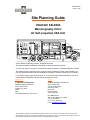
10338-D02-00
Page 1 of 20
Site Planning Guide
HOLOGIC SELENIA
Mammography Clinic
40’ Self-propelled USA Unit
© 2010 Oshkosh Specialty Vehicles, All Rights Reserved.
This manual contains confidential information of Oshkosh Specialty Vehicles.
You may not copy it or any part of it without the written permission of Oshkosh Specialty Vehicles.
This manual may be used only by you, and only for the purposes for which it was intended. You
may not disclose this manual or the confidential information it contains outside of your company.
If you wish to copy any part of this manual, or to use it other then as described above, you must
contact Oshkosh Specialty Vehicles seeking permission to do so.
North America
Europe
Corporate Headquarters
Oshkosh Specialty Vehicles, Ltd.
Oshkosh Specialty Vehicles
Unit 17, Nelson Way
Tuscum Trading Estate,
Camberley, Surrey
GU15 3DH
United Kingdom
(44) 01276.64490
2150 E. Dolton Road
Calumet City, Illinois
60409
USA
(001) 800.839.0630 (24 hour service)
Buys Ballotstraat 6
3261 LA Oud-Beijerland, Holland
+31 (0) 186-614322
Fax. +31 (0) 186-619367
E-mail: [email protected]
The information contained in this booklet is the property of OSV. The contents are confidential. They may not be used,
either partially or wholly, for any purpose inconsistent with the purpose for which it was produced. The contents may not be
reproduced or disclosed without written permission of Oshkosh Specialty Vehicles.
10338-D02-00
Page 2 of 20
List of Revisions
Revisions
00
Initial Release
February 2010
Notice
In accordance with our policy of continued product improvement, Oshkosh Specialty Vehicles
reserves the right to make changes in the equipment, design, specifications, and materials of the
product described herein. Any problems or questions related to the components or systems
covered in this booklet may be directed to:
Oshkosh Specialty Vehicles
2150 E. Dolton Road
Calumet City, Illinois
60409
USA
(001) 800.839.0630 (24 hour service)
(001) 708.868.5101 (fax)
http://www.osjkoshsv.com/
The information contained in this booklet is the property of OSV. The contents are confidential. They may not be used,
either partially or wholly, for any purpose inconsistent with the purpose for which it was produced. The contents may not be
reproduced or disclosed without written permission of Oshkosh Specialty Vehicles.
10338-D02-00
Page 3 of 20
Table of Contents
Introduction........................................................................................................... 5
Warnings & Safety Alert Conventions .............................................................................................5
Support Pad Requirements ................................................................................. 6
Recommended Support Pad Requirements ...................................................................................6
Support Pad Depth ..........................................................................................................................6
Support Pad Levelness ...................................................................................................................6
Recommended Service Pad............................................................................................................6
Vehicle Access ................................................................................................................................6
Recommended Attachment to the Facility ......................................................................................6
Swing Clearance Note.....................................................................................................................6
Radiation Shielding..........................................................................................................................7
Customer Power Requirements .......................................................................... 8
Lockout/Tagout................................................................................................................................8
Electrical Service .............................................................................................................................8
Configuration ...................................................................................................................................8
Load Regulation at Line Frequency ................................................................................................8
Frequency........................................................................................................................................8
Phase Balance ................................................................................................................................8
Maximum Voltage Variation ............................................................................................................8
Connector Type ...............................................................................................................................9
Customer Facility.............................................................................................................................9
Connector Notes..............................................................................................................................9
Voltage Surges ................................................................................................................................9
Power Source Monitoring (Facility Only) .........................................................................................9
Mobile Grounding Requirements ...................................................................... 10
Special Ground Note .....................................................................................................................10
Telephone Service Requirements ..................................................................... 11
Telephone Service.........................................................................................................................11
Data Service ..................................................................................................................................11
Water Requirements........................................................................................... 13
Fresh Water Supply Requirements ...............................................................................................13
The information contained in this booklet is the property of OSV. The contents are confidential. They may not be used,
either partially or wholly, for any purpose inconsistent with the purpose for which it was produced. The contents may not be
reproduced or disclosed without written permission of Oshkosh Specialty Vehicles.
10338-D02-00
Page 4 of 20
Table of Figures
Figure 1: Fire Alarm Cable Connections .......................................................................................... 12
Figure 2: Pad Layout ........................................................................................................................ 14
Figure 3: Right Side Elevation.......................................................................................................... 15
Figure 4: Left Side Elevation ............................................................................................................ 16
Figure 5: Front & Rear Side Elevation ............................................................................................. 17
Figure 6: Russellstoll Service Outlet ................................................................................................ 18
Figure 7: Russellstoll 240V Chart..................................................................................................... 19
Figure 8: Turning Requirements ...................................................................................................... 20
The information contained in this booklet is the property of OSV. The contents are confidential. They may not be used,
either partially or wholly, for any purpose inconsistent with the purpose for which it was produced. The contents may not be
reproduced or disclosed without written permission of Oshkosh Specialty Vehicles.
10338-D02-00
Page 5 of 20
Introduction
The purpose of this document is to provide the basic information needed for site planning. For
specific information not contained in this document, please contact Oshkosh Specialty Vehicles.
The mobile self-propelled unit requires sufficient room to be maneuvered and positioned for setup
and takedown. The mobile self-propelled unit has many storage compartments and service doors
that require access during these procedures as well as during operation. The wheel chair lift, entry
stair and optional platform require additional space on the right side of the mobile self-propelled
unit. Refer to the drawings provided for actual locations of doors, wheel chair lift, and stair sizes
and locations.
Warnings & Safety Alert Conventions
Three types of statements are used throughout this document to warn the operator of potential
situations. Always read these statements carefully and take the appropriate safety precautions to
ensure a safe environment for all personnel and all property. The statements are as follows:
This type of notice indicates a potentially hazardous situation, which if not
avoided, could result in injury or death to the operator of the mobile selfpropelled unit.
This type of notice indicates a potentially hazardous situation, which if not
avoided, could result in irreparable damage to the mobile self-propelled unit.
This type of notice is meant to inform the operator of useful information.
The information contained in this booklet is the property of OSV. The contents are confidential. They may not be used,
either partially or wholly, for any purpose inconsistent with the purpose for which it was produced. The contents may not be
reproduced or disclosed without written permission of Oshkosh Specialty Vehicles.
10338-D02-00
Page 6 of 20
Support Pad Requirements
The following is a list of recommendations and requirements for a concrete support pad. However,
due to varying site conditions, the actual pad design should be prepared by an appropriately
licensed structural or architectural engineer.
Recommended Support Pad Requirements
A full pad measuring 10’-11” x 31’-8-3/4” is the recommended support pad. The cross hatching as
shown on Figure 2: Pad Layout, Figure 3: Right Side Elevation, and Figure 4: Left Side
Elevation represents the recommended support pad.
Support Pad Depth
Recommendations for the width and length of the pad are given above. Based upon the weight
distribution of the mobile unit and existing site conditions, the depth should be determined by a
local contractor.
Support Pad Levelness
In order to ensure proper operation of the system, the support pad(s) must be level and the
deviation must not exceed 2” in 10’-0”.
Recommended Service Pad
A full pad measuring 18’-4” x 45’-5" is the recommended service pad. This will allow full service
access to the mobile unit. The recommended service pad is shown on Figure 2: Pad Layout,
Figure 3: Right Side Elevation, and Figure 4: Left Side Elevation.
Vehicle Access
A firm, level surface is required around the mobile unit in order to provide access to the site, patient
access to the mobile unit, and servicing of the mobile unit.
Recommended Attachment to the Facility
An inflatable air bag or soft seal is recommended at the point of connection from the unit to the
facility. Fixed or solid connections may hinder imaging quality. Contact Oshkosh Specialty Vehicles
or the local Hologic Selenia representative prior to construction if the proposed connection varies
from the recommended.
Swing Clearance Note
Please verify the actual dimensions of the rearmost projections on the mobile self-propelled unit to
the centerline of tandem suspension. Refer to Figure 8: Turning Requirements for proper turning
requirements.
The information contained in this booklet is the property of OSV. The contents are confidential. They may not be used,
either partially or wholly, for any purpose inconsistent with the purpose for which it was produced. The contents may not be
reproduced or disclosed without written permission of Oshkosh Specialty Vehicles.
10338-D02-00
Page 7 of 20
Radiation Shielding
Radiation exposure limits must be in accordance with all local, state, and
federal requirements. It is the responsibility of the customer to perform a
proper radiation survey in order to determine the exclusion zone.
Care should be taken when determining a site location. Factors such as shielding design, proximity
to buildings, and occupancy of the surrounding areas must be considered. The mobile unit has
been designed to provide radiation shielding for the areas adjacent to the procedure room. An
exclusion zone around the mobile unit may be necessary. Please contact Oshkosh Specialty
Vehicles for mobile unit specific shielding information.
The information contained in this booklet is the property of OSV. The contents are confidential. They may not be used,
either partially or wholly, for any purpose inconsistent with the purpose for which it was produced. The contents may not be
reproduced or disclosed without written permission of Oshkosh Specialty Vehicles.
10338-D02-00
Page 8 of 20
Customer Power Requirements
It is the operator’s responsibility to verify that the shore power receptacle is
electrically compatible with the mobile unit’s power cable and connector prior
to connecting to the shore power connection. Plugging into a receptacle not
electrically compatible could cause serious injury or damage.
The standard connector for the unit is a Russellstoll DS2307MP (240V AC). If
an existing site currently implements a different connector or connector
configuration, please contact Oshkosh Specialty Vehicles in order to arrange
for a compatible power connector before the unit leaves the facility.
Always inspect the power cable, connectors, and fasteners prior to usage. If
during inspection, it is suspected that either internal or external damage has
occurred, have a certified electrician inspect and repair the damage before
using.
Follow the maintenance schedule in the Operator and Service Manual for safe
operation of the mobile unit.
Lockout/Tagout
A Lockout/Tagout provision in accordance with OSHA Standard 1910.147 is required. The facility
shore power disconnect device must be located within 40’- 0” of the unit and must provide for an
effective lockout/tagout to facilitate safe service and maintenance of the unit.
Electrical Service
240V AC, single phase, fused at 150 amps.
Configuration
Single-phase connection, three wire, with ground.
Load Regulation at Line Frequency
Wires are to be sized such that the line voltage drops from the power source to the mobile unit is
less then 6% of the nominal voltage for the rated load of the mobile unit.
Frequency
60Hz ±0.5Hz.
Phase Balance
The phase balance is 2% maximum of lowest phase-to-phase voltage.
Maximum Voltage Variation
The maximum voltage variation is ±2% from a nominal steady state (under the worst case
conditions of line voltage).
The information contained in this booklet is the property of OSV. The contents are confidential. They may not be used,
either partially or wholly, for any purpose inconsistent with the purpose for which it was produced. The contents may not be
reproduced or disclosed without written permission of Oshkosh Specialty Vehicles.
10338-D02-00
Page 9 of 20
Connector Type
The mobile unit is supplied with a 50’-0” power cables and male connector. Unless otherwise
specified, the 240V AC connector is a Russellstoll DS2307MP000.
Customer Facility
The customer facility must have the matching receptacle as specified in Figure 6: Russellstoll
Service Outlet and Figure 7: Russellstoll 240V Chart. Unless otherwise specified, the 240V AC
receptacle to be used is a Russellstoll DF2307FRAB0.
Connector Notes
The standard connector for the mobile unit is a Russellstoll. The mobile unit is configured for 240V
AC, single phase, 60 Hz. Many existing mobile sites are set up for a variety of different mobile units
that this mammography clinic could utilize. Review the different site configurations to determine the
best location for the mammography clinic on these sites If an existing site currently implements a
different connector, connector configuration, or the available power supply varies from the above
specifications, please contact Oshkosh Specialty Vehicles to arrange for a compatible power
connector before the mobile unit leaves the facility.
Voltage Surges
Transient voltage variations caused by external loads must not:
•
Exceed ±5%.
•
Exceed five cycles duration.
•
Occur more then ten times an hour.
Power Source Monitoring (Facility Only)
NOTE: Perform a power audit first.
A power analyzer should be used to check the proposed Mobile Hologic Selenia Series facility site
power for average line voltage, surges, sags, reclosures, impulses, frequency and microcuts. A
period that includes two weekends should be used to simulate several days of normal use.
Analysis of the data and site history of any previous power problems with other X-ray systems or
computer installations should be reviewed with your power and ground representative. Verify
“brown-out” (low voltage) conditions, which may occur during summer months, will not exceed the
allowable range.
Some analyzer models that are suitable for power monitoring are:
•
Dranetz Model 658
•
Dranetz Model 656A
•
BMI 3630
•
RPM
The information contained in this booklet is the property of OSV. The contents are confidential. They may not be used,
either partially or wholly, for any purpose inconsistent with the purpose for which it was produced. The contents may not be
reproduced or disclosed without written permission of Oshkosh Specialty Vehicles.
10338-D02-00
Page 10 of 20
Mobile Grounding Requirements
All work is to be done in accordance with the local and national electrical
codes.
Information shown here is only a recommendation and must be verified with
both local and national site codes.
Ground wires inside enclosures are to be taped green for the entire visual
length for identification purposes.
If a separately derived, secondary system transformer is used, a bonding
jumper between the grounded conductor (neutral) and the equipment –
grounding conductor must be used.
Special Ground Note
The mobile unit must have an earth driven ground rod within 5’-0” of the facility power receptacle. A
grounding cable of a minimum #1/0 AWG must be connected between the grounding rod and the
grounding pin of the facility power receptacle. A separate grounding conductor must still be run with
the phase conductors to the source of the power from the grounding pin of the hospital power
receptacle in accordance with NEC 2002 Article 250-24.
The information contained in this booklet is the property of OSV. The contents are confidential. They may not be used,
either partially or wholly, for any purpose inconsistent with the purpose for which it was produced. The contents may not be
reproduced or disclosed without written permission of Oshkosh Specialty Vehicles.
10338-D02-00
Page 11 of 20
Telephone Service Requirements
Telephone Service
The mobile unit is supplied with two (2) telephone connections. The connector type that is used is
an RJ-12 plug.
The customer is required to purchase and install two (2) telephone lines, RJ-11 or RJ-12 modular
plugs for use at the site.
Data Service
The mobile unit is supplied with four (4) data line connections that utilize RJ-45 outlets.
The customer is required to purchase the data connection cables for use with the data line
connections. The data line connections require a 50’-0” CAT-5E cable with RJ-45 connections.
Data Service
For fire alarm connections see Figure 1: Fire Alarm Cable Connections below.
The information contained in this booklet is the property of OSV. The contents are confidential. They may not be used,
either partially or wholly, for any purpose inconsistent with the purpose for which it was produced. The contents may not be
reproduced or disclosed without written permission of Oshkosh Specialty Vehicles.
10338-D02-00
Page 12 of 20
Figure 1: Fire Alarm Cable Connections
The information contained in this booklet is the property of OSV. The contents are confidential. They may not be used,
either partially or wholly, for any purpose inconsistent with the purpose for which it was produced. The contents may not be
reproduced or disclosed without written permission of Oshkosh Specialty Vehicles.
10338-D02-00
Page 13 of 20
Water Requirements
Fresh Water Supply Requirements
The mobile unit will require a ¾” diameter, 20’-0” long hose terminated with a ¾” female threaded
hose connector to replenish fresh water for the humidifier onboard the mobile unit. The facility must
provide a ¾” male connector and a water supply that meets the following specifications:
•
A flow rate of 5 gallons per minute.
•
45-60 PSI.
•
A maximum temperature of 70°F.
The information contained in this booklet is the property of OSV. The contents are confidential. They may not be used,
either partially or wholly, for any purpose inconsistent with the purpose for which it was produced. The contents may not be
reproduced or disclosed without written permission of Oshkosh Specialty Vehicles.
10338-D02-00
Page 14 of 20
Figure 2: Pad Layout
The information contained in this booklet is the property of OSV. The contents are confidential. They may not be used, either partially or wholly, for any purpose
inconsistent with the purpose for which it was produced. The contents may not be reproduced or disclosed without written permission of Oshkosh Specialty Vehicles.
10338-D02-00
Page 15 of 20
X-RAY ON
®
OSHKOSH
SPECIALTY
VEHICLES
Figure 3: Right Side Elevation
The information contained in this booklet is the property of OSV. The contents are confidential. They may not be used, either partially or wholly, for any purpose
inconsistent with the purpose for which it was produced. The contents may not be reproduced or disclosed without written permission of Oshkosh Specialty Vehicles.
10338-D02-00
Page 16 of 20
Figure 4: Left Side Elevation
The information contained in this booklet is the property of OSV. The contents are confidential. They may not be used, either partially or wholly, for any purpose
inconsistent with the purpose for which it was produced. The contents may not be reproduced or disclosed without written permission of Oshkosh Specialty Vehicles.
10338-D02-00
Page 17 of 20
Figure 5: Front & Rear Side Elevation
The information contained in this booklet is the property of OSV. The contents are confidential. They may not be used, either partially or wholly, for any purpose
inconsistent with the purpose for which it was produced. The contents may not be reproduced or disclosed without written permission of Oshkosh Specialty Vehicles.
10338-D02-00
Page 18 of 20
Figure 6: Russellstoll Service Outlet
The information contained in this booklet is the property of OSV. The contents are confidential. They may not be used, either partially or wholly, for any purpose
inconsistent with the purpose for which it was produced. The contents may not be reproduced or disclosed without written permission of Oshkosh Specialty Vehicles.
10338-D02-00
Page 19 of 20
Figure 7: Russellstoll 240V Chart
The information contained in this booklet is the property of OSV. The contents are confidential. They may not be used, either partially or wholly, for any purpose
inconsistent with the purpose for which it was produced. The contents may not be reproduced or disclosed without written permission of Oshkosh Specialty Vehicles.
10338-D02-00
Page 20 of 20
Figure 8: Turning Requirements
The information contained in this booklet is the property of OSV. The contents are confidential. They may not be used, either partially or wholly, for any purpose
inconsistent with the purpose for which it was produced. The contents may not be reproduced or disclosed without written permission of Oshkosh Specialty Vehicles.