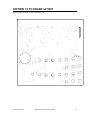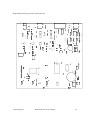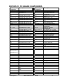
1
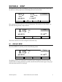
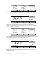
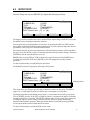
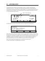
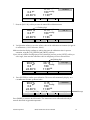
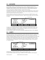
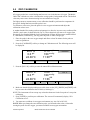
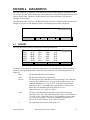
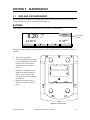
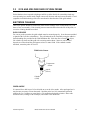
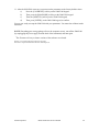
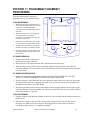
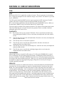
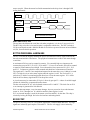
YSI MODEL 5000
YSI MODEL 5100
Dissolved Oxygen
Temperature
SERVICE MANUAL
TABLE OF CONTENTS
Section 1 General Description ..................................................................................................... 1
Section 2 Specifications ................................................................................................................ 2
Section 3 Software Flow Chart.................................................................................................... 3
Section 4 Setup .............................................................................................................................. 4
4.1
4.2
4.3
4.4
Display Setup .................................................................................................................... 4
Report Setup ..................................................................................................................... 6
Autostable Setup .............................................................................................................. 7
System Setup..................................................................................................................... 8
Section 5 Calibration .................................................................................................................. 10
5.1 Dissolved Oxygen Calibration....................................................................................... 10
Auto Cal........................................................................................................................... 10
DO Cal (manual)............................................................................................................. 11
5.2 Barometer ....................................................................................................................... 13
5.3 Salinity............................................................................................................................. 13
5.4 Zero Calibration............................................................................................................. 14
Section 6 Diagnostics .................................................................................................................. 15
6.1 History............................................................................................................................. 15
6.2 Sensor .............................................................................................................................. 16
6.3 Reset Ps ........................................................................................................................... 16
Section 7 Troubleshooting Chart .............................................................................................. 17
Section 8 Test Procedure............................................................................................................ 19
Section 9 Maintenance................................................................................................................ 21
9.1 5000 and 5100 Instruments ........................................................................................... 21
Batteries........................................................................................................................... 21
9.2 5910 and 5905 Dissolved Oxygen Probes ..................................................................... 22
Electrode Cleaning ......................................................................................................... 22
Section 10 Software Upgrade Procedure.................................................................................. 23
Section 11 Disassembly/Assembly Procedures......................................................................... 25
Section 12 Circuit Description................................................................................................... 26
Section 13 Schematic Diagrams ................................................................................................ 30
Section 14 PC Board Layout...................................................................................................... 37
Section 15 PC Board Components ............................................................................................ 39
Section 16 Accessories and Replacement Parts ....................................................................... 40
Section 17 Warranty and Repair .............................................................................................. 41
i
ii
SECTION 1
GENERAL DESCRIPTION
MODEL 5000 FEATURES
The Model 5000 is a microprocessor based, menu-driven, dissolved oxygen meter designed to
perform laboratory measurement of dissolved oxygen and Biochemical Oxygen Demand (BOD).
The angled profile makes these instruments both functional and attractive. A large graphical
display provides on-screen menus, and large data fields for ease of operation and readability. The
angle and position of the keypad make operation of the 5000 comfortable. The tactile and audio
response from each key stroke give you the confidence that every command has been received.
The Model 5000 is compatible with all existing YSI dissolved oxygen probes when used with the
YSI Model 5011 adapter. The new YSI Model 5010 self-stirring BOD Probe allows you to
operate the probe from the instrument’s power supply, eliminating the need for a separate power
cable for the probe.
Internal memory for storing up to 100 sets of data, and an RS232 port allow you to upload data
from the Model 5000 directly to your computer. Or you can use your Model 5000 with YSI BOD
Analyst software.
MODEL 5100 FEATURES
The YSI Model 5100 has all of the same functionality of the Model 5000 plus many automated
and application specific features.
The YSI 5100 is the first DO instrument to offer built-in application software for the calculation
of Oxygen Uptake Rate (OUR) and Specific Oxygen Uptake Rate (SOUR). These application
features simplify compliance with USEPA 503 regulations for vector attraction and provide
useful tools for plant operation decisions.
For laboratories with larger volumes, the Model 5100 offers bar code scanner and BOD Analyst
software capability. These tools greatly reduce the labor required for processing BODs and
calculating BOD values. The RS232 serial port makes it easy to capture data electronically.
The model 5000 and 5100 software can be upgraded easily using your computer. When YSI
upgrades these instruments, you’ll be able to get a floppy disk from YSI and simply upgrade the
software in a few minutes.
Calibration of the Model 5100 has been greatly simplified when compared to other dissolved
oxygen instruments. With it’s internal barometer, the Model 5100 is able to automatically
compensate for changes in barometric pressure so there is no need for charts, altitude information
or external barometric pressure information.
YSI Incorporated
Model 5000/5100 Service Manual
1
SECTION 2
SPECIFICATIONS
OXYGEN MEASUREMENT
Ranges:
mg/L: 0.0 to 60.0 mg/L
% air saturation: 0.0 to 600.0% air saturation
mbar: 0.0 to 1500
Accuracy:
mg/L: ±0.1% plus 1 Least Significant Digit (LSD)
% air saturation: ±0.1% plus 1 LSD
mbar: ±1% plus 1 LSD
Resolution:
mg/L: 0.1%, or 0.01 mg/L , whichever is greater
% air saturation: 0.1% air saturation
mbar: 1 mbar
TEMPERATURE MEASUREMENT
Range: -5.0 to +50.0°C
Accuracy:
±0.1°C
Resolution:
0.01°C
BAROMETRIC PRESSURE MEASUREMENT
Range: 450 to 825 mmHg (600 to 1100 mbar)
Accuracy:
±1% plus 1 LSD within ±10°C ambient temperature from calibration point
Resolution:
1 mmHg
TEMPERATURE COMPENSATION
The mg/L mode is automatically temperature-compensated to an accuracy of ±1% of DO
readings between 0 and 5°C, and to an accuracy of ±0.6% of readings between 5 and 45°C.
The % air saturation mode is automatically temperature-compensated to an accuracy of ±0.5% of
calibration values between 0 and 5°C, and to an accuracy of ±0.3% of values between 5 and
45°C.
SALINITY COMPENSATION
Range: 0.0 to 40.0 ppt
Accuracy: ±.02 mg/L
OPERATING ENVIRONMENT
0 to 45°C, 10 to 90% relative humidity, non-condensing
WATER RESISTANCE
The Model 5000 and 5100 are designed exclusively for indoor use and are NOT waterproof.
POWER
The Model 5000 & 5100 are powered by an AC adapter or 4 C-size alkaline batteries. A new set
of alkaline batteries will power the selected instrument for approximately 30 hours (not including
stirring).
YSI Incorporated
Model 5000/5100 Service Manual
2
SECTION 3
SOFTWARE FLOW CHART
The following section shows the software flow chart for the 5000/5100. The two operating
modes, Main and Application, are shown at the top with the soft-key functions that are accessed
in each mode below them. Functions in shaded boxes are only available on the model 5100.
M AIN
APPLICATIO N
OUR
Store
Start
Reveiw
Recall
End
Print All
Print on/off
Clear
Setup
Delete All
Print on/off
Print All
Send
SOUR
CALIBR ATE
Auto Cal
Start
End
DO Cal
Print on/off
SETU P
Setup
Display
Size
Unit
Contrast
Print on/off
Print All
Rem ote
Last Digit
Skip
Report
Up
SDF
Down
CDF
Confirm
Range
Next
Stable
System
Audio O n/O ff
Tim e/Date
Version
RS-232
DIAGNO SIS
YSI Incorporated
Model 5000/5100 Service Manual
3
SECTION 4
SETUP
From Main mode, press the [CALIBRATE] soft-key to enter the calibration menu. Notice that
the dark bar in the top right corner of the display shows the current mode.
8.15 mg/L
740 mmHg
11:33AM
98.0 %
0.0 ppt
24.38°C
AUTO CAL
DO CAL
SETUP
Calibrate
DIAGNOSTICS
Next, press the [SETUP] soft-key to enter the Setup menu. The bottom row of the display will
show the following soft-key setup selections.
8.15
*
Setup
mg
/L
11:33AM
24.38°C
DISPLAY
REPORT
STABLE
SYSTEM
These four selections are used to change the instrument setup.
4.1
DISPLAY SETUP
Press the [DISPLAY] soft-key to show the following menu.
8.15
*
Display
mg
/L
11:33AM
24.38°C
SIZE
UNITS
CONTRAST
LAST DIG.
The [SIZE] soft-key cycles among the two possible display arrangements for Main mode. One
selection shows as many parameters as possible, the other shows Dissolved Oxygen in large type
with temperature and time in small type.
YSI Incorporated
Model 5000/5100 Service Manual
4
8.15 mg/L
740 mmHg
11:33AM
98.0%
0.0 ppt
24.38°C
SIZE
UNITS
CONTRAST
Display
LAST DIG.
The [UNITS] soft-key changes the display unit(s) of Dissolved Oxygen. When you have selected
a large size display, the DO number cycles among the three possibilities, percent, milligrams per
liter and millibars.
*
Display
92.2 %
11:33AM
24.38°C
SIZE
UNITS
CONTRAST
LAST DIG.
If the small size display has been selected, the dual DO display cycles among the three
possibilities, percent and milligrams per liter, milligrams per liter and millibars or percent and
millibars. An example is shown below.
8.71 mg/L
0.0 ppt
24.38°C
SIZE
208 mbar
740 mmHg
11:33AM
UNITS
CONTRAST
Display
LAST DIG.
The [CONTRAST] soft-key allows the user to change the display contrast. The display contrast
will change slightly each time the [UP] or [DOWN] soft-key is pressed.
The [LAST DIG.] soft-key allows the user to suppress the last digit of the DO reading.
8.2
*
Display
mg
/L
11:33AM
24.38°C
SIZE
UNITS
CONTRAST
LAST DIG.
Press the [MODE] key to return to the Setup menu. If you wish to return to Main mode, press
[MODE] two more times.
YSI Incorporated
Model 5000/5100 Service Manual
5
4.2
REPORT SETUP
From the Setup menu, press [REPORT] to display the following soft-keys.
[SDF] Space Delimited Format
[*] SAMPLE ID #
[*] DATE
[*] DO%
[*] TIME
[*] DO mg/L
[*] BAROMETER
[*] TEMPERATURE
[*] SALINITY
PRINT Record from [ 0] to [99]
SDF
CDF
RANGE
Report
NEXT
The display lists the parameters that can be included in the output string at the RS232 serial port,
the default set has everything selected for inclusion.
You can select the report format that you wish to use by pressing the [SDF] or [CDF] soft-key.
Select [SDF] for Space Delimited Format (standard text). If you are going to import the data to a
spreadsheet, select [CDF] for Comma Delimited Format.
The asterisk character in front of each parameter indicates that the parameter will be included in
the report. Press the [NEXT] soft-key to select the parameter that you want to change. Then press
[ENTER] to turn the asterisk character on or off.
NOTE: After pressing [SDF] or [CDF] to choose the report format, press the [MODE] key to
exit the Report menu. Do NOT press [ENTER] as this will change the currently selected
parameter.
To return to Main mode, press [MODE] two more times.
The [RANGE] soft-key brings up the following soft-key menu.
[SDF] Space Delimited Format
[*] SAMPLE ID #
[*] DATE
[*] DO%
[*] TIME
[*] DO mg/L
[*] BAROMETER
[*] TEMPERATURE
[*] SALINITY
PRINT Record from [ 00] to [99]
UP
DOWN
DIGIT
Report
Flashing Cursor
NEXT
This menu allows specifying a specific range of memory locations for the report. The default
range is 00 - 99 and empty locations will not be sent to a computer or serial printer.
The display digit that has the flashing cursor below it is increased or decreased by pressing the
[UP] or [DOWN] soft-key. If the [UP] or [DOWN] soft-key is held down, the digit will continue
to change until the key is released. The [DIGIT] soft-key makes it easy to make large changes by
selecting the digit you wish to change. Press the [NEXT] soft-key to change between the
minimum and maximum parameter. When the desired number is obtained, pressing [ENTER]
will accept the number and exit the RANGE sub-menu.
To return to Main mode, press [MODE] three more times.
YSI Incorporated
Model 5000/5100 Service Manual
6
4.3
AUTOSTABLE SETUP
The autostable feature indicates when readings are stable by emitting a single beep and
displaying an asterisk (*) to the right of the dissolved oxygen reading. The instrument uses
criteria that you input to determine what a stable reading is. You select the maximum percent of
change that may occur during a selected time duration. The instrument will display an asterisk
(*) only when these criteria are met.
Stable reading indication
8.20
*
Main
mg
/L
11:33AM
24.38°C
STORE
REVIEW
SEND
CALIBRATE
From the Setup menu, press the [STABLE] soft-key to display the following menu.
Stable
PARAMETERS
[ 10] Time Duration (3-19) Seconds
[0.3] DO % variation (0.0-1.9)
UP
DOWN
DIGIT
NEXT
This menu is used to change the autostable criteria. Press the [NEXT] soft-key to select between
the time duration and the percent variation. Use the [DIGIT] soft-key to select the digit you wish
to change by pressing [UP] or [DOWN]. When you have finished setting the parameters, press
[ENTER] to confirm. The STABLE sub-menu can be left without making any changes by
pressing the [MODE] key instead of [ENTER]. Operation returns to the setup menu.
If you wish to disable the autostable feature, set the DO% variation to 0.0.
To return to Main mode, press [MODE] two more times.
YSI Incorporated
Model 5000/5100 Service Manual
7
4.4
SYSTEM SETUP
From the Setup menu, press the [SYSTEM] soft-key to display the following menu.
8.38
*
mg
/L
System
11:47AM
24.38°C
AUDIO off
TIME / DATE
VERSION
RS232
The [AUDIO on/off] soft-key allows setting the beeper on or off. The key toggles between an
[AUDIO off] soft-key and an [AUDIO on] soft-key. The present state of the beeper would be the
OPPOSITE of the function shown on the soft-key. If the beeper is currently on, the soft-key
shows “AUDIO off”; i.e., your alternate choice.
The [TIME/DATE] soft-key brings up the following menu to allow setting of the date and time.
Flashing Digit
Time/Date
09:58:04
01/20/96
UP
DOWN
DIGIT
NEXT
Use the UP, DOWN, DIGIT and NEXT soft-keys to enter the time in 24-hour format. The
display digit that is flashing is increased or decreased by pressing the [UP] or [DOWN] soft-key.
If the [UP] or [DOWN] soft-key is held down, the digit will continue to change until the key is
released. After you have set the hour, press the [NEXT] soft-key to move to the next parameter,
minutes. Repeat the process for the remaining parameters.
When you have finished entering the time and date, press [ENTER] to confirm and return to the
system setup menu. The message “TIME SETTING SAVED” will be displayed on the message line
at the bottom of the screen. The Time/Date sub-menu can be left without making any changes by
pressing the [MODE] key instead of [ENTER].
8.38
*
mg
/L
System
9:59AM
24.38°C
TIME SETTING
AUDIO off
SAVED
TIME / DATE
Message
VERSION
RS232
The [VERSION] soft-key displays the software version of the instrument on the message line of
the display just above the soft-key descriptions.
The [RS232] soft-key displays the RS232 setup.
YSI Incorporated
Model 5000/5100 Service Manual
8
[ 2 ] BAUD RATE
19200
0.
1.
2. 19200
3. 9600
4. 4800
5. 2400
6. 1200
UP
RS232
DOWN
Select the baud rate by pressing the [UP] or [DOWN] soft-keys.
The remaining RS232 parameters are fixed as follows:
Data Length:
8 bits
Parity:
None
Stop Bits:
1
Press [ENTER] to confirm. The RS232 sub-menu can be left without making any changes by
pressing the [MODE] key instead of [ENTER]. Operation returns to the system setup menu.
Press [MODE] to return to the previous menu, Setup. To return to Main mode, press [MODE]
two more times.
YSI Incorporated
Model 5000/5100 Service Manual
9
SECTION 5
CALIBRATION
The instructions below explain how to calibrate the system before dissolved oxygen
measurements are taken or testing is performed using the 16423 Test Box.
From the Main mode, press the [CALIBRATE] soft-key to enter Calibration mode. The bottom
row of the display shows the soft-key menu.
98.0*%
0.0 ppt
24.38°C
AUTO CAL
5.1
8.15 mg/L
740 mmHg
11:33AM
DO CAL
SETUP
Calibrate
DIAGNOSTICS
DISSOLVED OXYGEN CALIBRATION
Dissolved oxygen calibration can be done automatically with the push of one button (see AUTO
CAL) or manually by entering the desired value in milligrams per liter or percent saturation (see
DO CAL).
BEFORE YOU CALIBRATE you must Setup the meter, as discussed in the Setup section of
this manual, and Prepare the DO probe. Before performing an AUTO CAL, you must check the
barometric pressure reading and calibrate the barometer, if necessary, as shown under
Calibration, Barometer. The Model 5000 does not contain a barometer, therefore, the current
barometric pressure must be entered before an AUTO Cal is performed.
Dissolved oxygen calibration must be done in an environment with a known oxygen content. The
simplest method will be discussed here: calibration in air (water saturated). Calibration in air is
the simplest and most accurate method of calibration.
For air calibration, place the probe in air at 100% relative humidity. To achieve this, the probe
can be placed in a BOD bottle containing 1″ of water. No stirring is required in air.
AUTO CAL
1. Prepare the probe according to the instructions in the Probe Operations Manual.
2. Connect the probe to the meter.
3. Place the probe in a BOD bottle containing about 1″ of water to provide a 100% relative
humidity environment.
4. Press [
] to turn the instrument on.
5. Allow the probe to polarize and the temperature to stabilize for at least 15 minutes. If
calibration is performed prematurely the values will drift and may be out of specification.
6. Press the [CALIBRATE] soft-key to change to Calibration mode. The following display will
appear.
YSI Incorporated
Model 5000/5100 Service Manual
10
98.0*%
0.0 ppt
24.38°C
AUTO CAL
8.15 mg/L
740 mmHg
11:33AM
DO CAL
SETUP
Calibrate
DIAGNOSTICS
7. Model 5100: Verify that the barometer reading is correct. Calibrate the barometer, if
necessary, as shown under Calibration, Barometer.
Model 5000: Enter the current barometric pressure as shown under Calibration, Barometer.
8. Verify that the salinity is set to the correct value (0.0 ppt for air calibration). See Calibration,
Salinity.
Make sure that the display readings are stable, then press the [AUTO CAL] soft-key to calibrate
Dissolved Oxygen. The message “D.O. CALIBRATION SAVED” will be displayed for a few
seconds.
98.0*%
0.0 ppt
24.38°C
D. O. CALIBRATION
AUTO CAL
8.15 mg/L
740 mmHg
11:33AM
Calibrate
SAVED
DO CAL
Message
SETUP
DIAGNOSTICS
Press [MODE] to return to the Main mode. The instrument is now calibrated and ready to
measure dissolved oxygen and temperature. See Operation, Main Mode, Making Measurements.
DO CAL (MANUAL)
1. Prepare the probe according to the probe instructions.
2. Connect the probe to the meter.
3. Place the probe in a known oxygen environment, such as a BOD bottle containing about 1″
of water to provide a 100% relative humidity environment or a Winkler-titrated sample.
4. Press [
] to turn the instrument on.
5. Allow the probe to polarize and the temperature to stabilize for at least 15 minutes. If
calibration is performed prematurely the values will drift and may be out of specification.
6. Press the [CALIBRATE] soft-key to change to Calibration mode. The following screen will
be displayed.
YSI Incorporated
Model 5000/5100 Service Manual
11
8.15 mg/L
740 mmHg
11:33AM
0.0 ppt
24.38°C
AUTO CAL
DO CAL
SETUP
Calibrate
DIAGNOSTICS
7. Press the [DO CAL] soft-key to enter the manual DO calibration menu.
Flashing digit
8.15 mg/L
740 mmHg
11:33AM
98.0 %
0.0 ppt
24.38°C
UP
DOWN
DIGIT
Cal %
NEXT
8. Verify that the salinity is set to the salinity value of the calibration environment (0.0 ppt for
air calibration). ). See Calibration, Salinity.
Make sure that the display readings are stable, then enter the calibration value in percent
saturation, using the [UP], [DOWN] and [DIGIT] soft-keys.
If you wish to calibrate in milligrams per liter (instead of percent), use the [NEXT] soft-key to
select mg/L, then enter the calibration value in milligrams per liter as shown below.
Flashing digit
mg/L
Cal mg/L
mmHg
98.0*%
0.0 ppt
24.38°C
UP
9.
08.15
740
11:33AM
DOWN
DIGIT
NEXT
Press [ENTER] to confirm your calibration. The screen will momentarily display “D.O.
CALIBRATION SAVED” as shown below.
98.0*%
0.0 ppt
24.38°C
8.15 mg/L
740 mmHg
11:33AM
D. O. CALIBRATION
UP
Calibration
SAVED
DOWN
Message
DIGIT
NEXT
Press [MODE] to return to the Main mode. The instrument is now calibrated and ready to
measure dissolved oxygen and temperature.
YSI Incorporated
Model 5000/5100 Service Manual
12
5.2
BAROMETER
The YSI Model 5100 has an internal barometer for pressure compensation during AUTO
Dissolved Oxygen Calibration. This barometer only needs to be calibrated when it is no longer
reading the correct barometric pressure. If the 5100 is kept at a constant ambient temperature
(±10°C), the barometer calibration should be accurate for about 30 days.
The Model 5000 does not contain a barometer, therefore, the current barometric pressure must be
entered before an AUTO Cal is performed. The reading currently displayed is the value that was
entered and stored during the previous calibration.
From the calibration menu press the [DO CAL] soft-key, then press the [NEXT] soft-key until
the barometric pressure is flashing and “Barometer” appears in the top right corner of the display
as follows:
Flashing digit
98.0*%
0.0 ppt
24.38°C
8.15 mg/L
740 mmHg
11:33AM
Press ENTER to SAVE
UP
Barometer
SETTING
DOWN
DIGIT
NEXT
Using the [UP], [DOWN] and [DIGIT] soft-keys, enter the true local barometric pressure. This
corresponds to a reading from a mercury barometer. Do NOT use the pressure reported by the
weather bureau which has been corrected to sea level.
Press [ENTER] to confirm. The message “PRESSURE CALIBRATION SAVED” will be displayed.
5.3
SALINITY
Salt reduces the ability of water to hold oxygen in solution. Enter the salinity of the sample you are
measuring and the meter will automatically compensate for the effect of salinity on dissolved
oxygen. The default setting for salinity is 0.0 ppt. You can enter any value between 0.0 and 40.0 ppt.
From the Calibration menu press the [DO CAL] soft-key, then press the [NEXT] soft-key until
the salinity value is flashing. The top right corner of the screen will display “Salinity” as shown
in the following screen. Remember, if you are manually calibrating in mg/L in water saturated
air, salinity is 0.0 ppt.
Flashing digit
98.0* %
0.0 ppt
24.55°C
8.15 mg/L
740 mmHg
11:35AM
Press ENTER to SAVE
UP
Salinity
SETTING
DOWN
DIGIT
NEXT
Using the [UP], [DOWN] and [DIGIT] soft-keys, enter the salinity value.
Press [ENTER] to confirm. The message “SALINITY SETTING SAVED” will be displayed.
YSI Incorporated
Model 5000/5100 Service Manual
13
5.4
ZERO CALIBRATION
All oxygen probes have a small background current, even in the absence of oxygen. The Model
5000/5100’s default zero value is based on the average probe’s background current. This default
value may cause errors when measuring low concentrations of oxygen.
For highest accuracy measurements, a zero calibration should be performed to compensate for
the specific background current of the probe in use.
To calibrate to a true zero, place the probe in a zero oxygen environment and adjust the
calibration value to zero.
A standard method for creating such an environment is to dissolve in water excess sodium sulfite
(Na2SO3), and a trace of cobalt chloride (CoCl2). These chemicals will remove all oxygen from
the sample (See Standard Methods for the Examination of Water & Wastewater, method 4500-O
G, 19th edition). Alternatively, you may place the probe in 100% nitrogen gas.
1. Place the probe in the zero oxygen sample and allow at least 20 minutes for the probe to
come to equilibrium.
2. Press the [CALIBRATE] soft-key to change to Calibration mode. The following screen will
be displayed.
98.0*%
0.0 ppt
24.38°C
AUTO CAL
8.15 mg/L
740 mmHg
11:33AM
DO CAL
SETUP
Calibration
DIAGNOSTICS
3. Press the [DO CAL] soft-key to enter the manual DO calibration menu.
000.0*%
0.0 ppt
24.38°C
UP
0.00 mg/L
740 mmHg
11:33AM
DOWN
DIGIT
Cal %
NEXT
4. Make sure that the display readings are stable, then use the [UP], [DOWN] and [DIGIT] softkeys to enter the calibration value of 0.0% (or 0.00 mg/L).
NOTE: The instrument will not except any value other than zero for the first point of a two-point
calibration.
5. Press [ENTER] to confirm your calibration. The screen will momentarily display “D.O.
Calibration saved”.
6. You must now recalibrate in an oxygen environment (see Auto Cal or DO Cal).
NOTE: When you change the zero calibration point, you offset the other value, so that after
zeroing the probe for zero oxygen, you must recalibrate in an oxygen environment.
YSI Incorporated
Model 5000/5100 Service Manual
14
SECTION 6
DIAGNOSTICS
5000 and 5100s have a diagnostic mode that can be used for troubleshooting. In Diagnosis mode
you can view specific sensor information, such as DO probe current, DO background current and
pressure sensor offset. This data is useful when trying to isolate problems or prevent error
messages from occurring.
From the Main mode, press the [CALIBRATE] soft-key to enter Calibration mode, then press the
[Diagnosis] soft-key to enter Diagnosis mode. The following screen will be displayed.
Diagnosis
HISTORY
6.1
SENSOR
HELP
RESET Ps
HISTORY
Press the [HISTORY] soft-key to display the following information.
Date
02/01
02/02
02/05
02/06
02/07
Time
14:12
08:42
09:55
10:58
13:08
HISTORY
DO uA
16.8
16.3
17.0
17.1
16.9
SENSOR
%/uA
5.98
7.90
6.42
7.47
6.43
C
21.9
28.0
23.0
27.9
22.8
HELP
Diagnosis
RESET Ps
The History screen displays information about the last five DO calibrations. This information is
useful for tracking the performance of the DO probe/membrane. The following parameters are
displayed:
Date:
The date the calibration was performed.
Time:
The time the calibration was performed.
DO uA:
The dissolved oxygen calibration current in microamps. The calibration
current (100% saturation at sea level) of an ideal probe using a 1 mil
(standard) membrane is 13.7uA @ 20°C. If the probe current (100%
saturation @ 20°C, 1 mil membrane) is greater than 17.0uA or lower
than 8.0uA, the membrane/probe may need service. See
Troubleshooting, Error Codes, E3 and E4.
%/uA:
The slope of the dissolved oxygen probe in percent per microamp
corrected to 20°C. The slope of an ideal probe using a 1 mil membrane is
7.3 %/uA @ 20°C. If the probe slope (1 mil membrane) is greater than
12.6 %/uA or lower than 5.9 %/uA, the membrane/probe may need
service. See Troubleshooting, Error Codes, E3 and E4.
C:
The temperature at the time of calibration in °C.
YSI Incorporated
Model 5000/5100 Service Manual
15
6.2
SENSOR
Press the [SENSOR] soft-key to display the following sensor diagnostics screen:
System Parameters
Cal. Temperature
Probe Slope
Probe Offset
Probe Current =
Pressure Offset
Sensor
=
=
=
=
22.85 C
6.43 %/uA @20C
0.075 uA
16.91 uA
830 mbar
Cal. Temperature:
The temperature at the time of the last calibration in °C.
Probe Slope:
The slope of the dissolved oxygen probe in percent per
microamp corrected to 20°C. The slope of an ideal probe using a
1 mil membrane is 7.3%/uA @ 20°C. If the probe slope (1 mil
membrane) is greater than 12.6 %/uA or lower than 5.9 %/uA,
the membrane/probe may need service. See Troubleshooting,
Error Codes, E3 and E4.
Probe Offset:
The zero offset current (background current) of the DO probe in
microamps. The factory default value is 0.075 uA. This value
will only change when a zero calibration is performed (see
Calibration, Zero Calibration). If this value is greater than
0.15uA (after a zero calibration) the membrane/probe may need
service. See Troubleshooting, Error Code E2.
Probe Current:
The present (real time) DO probe current in microamps.
Pressure Offset:
The offset of the barometer in millibars.
Press [MODE] to return to the Diagnosis menu. Press [MODE] two more times to return to the
Main menu.
6.3
RESET PS
The [RESET Ps] soft-key (Reset Parameters) is used to reset all instrument parameters to the
factory default values. This is useful when the parameters have been changed or corrupted, such
as when new software is loaded. Press the [RESET Ps] soft-key to display the following:
Reset
Press ENTER to RESET Parameters
HISTORY
SENSOR
HELP
RESET Ps
Press [ENTER] to confirm. If you do NOT wish to reset the parameters, press [MODE] to return
to the Diagnosis menu.
YSI Incorporated
Model 5000/5100 Service Manual
16
SECTION 7
TROUBLESHOOTING CHART
Error Messages
The instrument performs a Power On Self Test each time it is turned on. The following error
codes are provided to facilitate troubleshooting.
Code/Problem
Error
Blank Display
Possible Cause
Correction
Dead / low batteries or
defective external power
supply
Replace batteries / test
power supply
5011 adapter improperly
connected
Unplug 5011 from power
supply connector
Internal power supply
Verify circuit operation using
DVM. Replace PCB.
failure
E1: Check Probe
Temperature under
range
Temperature over
range
E2: Check
Membrane
E3: Check
Membrane
YSI Incorporated
High Background
current (DO)
DO Low current
Connector improperly
installed
Check probe connection
Intermittent connection in
cable or plug
Repair or replace
Probe thermistor defective.
Should measure 2252 Ω @
25oC
Replace probe sensor assy.
Electrical leakage in
connector or cable
Repair or replace
Probe thermistor defective.
Should measure 2252 Ω @
25oC
Repair probe sensor assy.
Insufficient warm-up time
See Calibration procedure
Incorrect probe zeroing
procedure
See Zero Calibration
Probe needs servicing
See probe maintenance
instructions
Probe malfunction
Repair or replace
Insufficient electrolyte or
fouled membrane
Install new membrane and
KCl
Contaminated electrodes
See probe maintenance
instructions
Membrane too thick
Try another membrane
High resistance in probe
connection
Repair or replace
Model 5000/5100 Service Manual
17
Code/Problem
Error
Possible Cause
Correction
E4: Check
Membrane
DO High Current
Membrane too thin
Install new membrane and
KCl
Electrodes need resurfacing
See probe maintenance
instructions
Short circuit in probe, cable or
connector
Replace defective assembly
Membrane damaged
Replace membrane and KCl
Probe electrodes needs
servicing
See probe maintenance
instructions
Connector improperly
installed
Check probe connection
Intermittent connection in
cable or plug
Replace defective assy
Probe malfunction
Replace defective assy
E5: Check
Membrane
YSI Incorporated
DO unstable
Model 5000/5100 Service Manual
18
SECTION 8
TEST PROCEDURE
This produce is for use with the YSI 16423 Oxygen Test Box. If no test box is available, testing
can be performed by inputting the resistance values in column 2 of the charts below.
•
A display test and system check are automatically run upon instrument start up.
•
Allow the display to stabilize completely during the following calibration checks.
•
Last digit rounding feature should be left off.
•
If auto stable feature has been activated, an asterisk should appear one the LCD once the
reading is stable.
Note: Neither the Model 5100 nor the 5000 have internal calibration adjustments. If either fail
any of the following accuracy checks, they must be repaired before using.
1.
Temperature Range Check
A.
Plug the test box connector into a 5011 Adapter and then into either the
5000 or 5100, (IBT) Instrument Being Tested, set test box to A-1, set the IBT
to MAIN Mode.
B.
Set the test box to the following positions and note temp. display:
2.
Set Test Box to:
Resistor input, J5 Pins 4 & 5
Display Reading
A-1
9534 Ω ±0.25%
-5.0 ±0.2°C
A-2
4482 Ω ±0.25%
+10.0 ±0.2°C
A-3
2252 Ω ±0.25%
+25.0 ±0.2°C
A-4
984 Ω ±0.25%
+45.0 ±0.2°C
A-5
Infinity
E.1 CHECK PROBE
Oxygen Range Check - % Range
A.
Set test box to D-2 position, let the readings stabilize, and set the IBT to the
CALIBRATE, DO CAL mode. The display should have the last digit of the
% number flashing.
B.
Press the UP, DOWN and DIGIT soft keys as necessary for the display to
read zero - 0.0%, then press the ENTER key to store the settings.
C.
The message line on the display should briefly say DO CALIBRATION
SAVED and the DO indicated as 0.0% and 0.00 Mg/L with temperature still
10.0oC (See above chart).
D.
Set test box to A-2 and allow display to stabilize. Press the DO CAL soft key
to enter DO CAL mode again. Press the UP, DOWN and DIGIT soft keys as
necessary for the display to read 100.0%. Press the ENTER key again to
store settings.
E.
YSI Incorporated
Perform the following checks for 02%.
Model 5000/5100 Service Manual
19
3.
Set Test Box to:
Resistor input, J5 Pins 2 & 3
Display Reading
A-2
88.2k Ω ±0.1%
100.0 ±0.1%
B-2
111.42k Ω ±0.1%
79.1 ±0.2%
C-2
250.0k Ω ±0.1%
35.3 ±0.2%
D-2
Infinity
0.0 ±0.1%
Oxygen Range Check - Mg/L Range (Salinity set at 0.0)
A.
Set test box to A-2 position allow the display to stabilize, set the IBT
to the CALIBRATE, DO CAL mode again. Temperature still at 10 oC.
B.
Press the NEXT soft-key once. The display should have the last digit of the
mg/L number flashing.
4.
5.
C.
Press the UP, DOWN and DIGIT soft keys as necessary for the display to
read 11.28 Mg/L. Press the ENTER key to store the value.
D.
Perform the following checks for Mg/L 02:
Set Test Box to:
Resistor input, J5 Pins 2 & 3
Display Reading
A-2
88.2k Ω ±0.1%
11.28 ±0.02 Mg/L
B-2
111.42k Ω ±0.1%
8.92 ±0.02 Mg/L
C-2
250.0k Ω ±0.1%
3.97 ±0.02 Mg/L
D-2
Infinity
0.00 ±0.01 Mg/L
Salinity Compensation Check
A.
Set test box to A-2 position Press the DO CAL soft key to enter DO CAL
mode again. Press the NEXT soft-key twice. Press the UP, DOWN and
DIGIT soft keys as necessary until the display reads 10.0 ppt. The Mg/L
display should read 10.58± .02 Mg/L.
B.
Set the salinity value to 35.0. The display should read 9.02 ±.02 Mg/L.
C.
Press the MODE key to leave CALIBRATION mode without saving the
changes.
Polarizing Voltage Check
A.
Set test box to position F-1.
B.
Connect a millivolt meter to the test box red and black binding posts ( Same
as, J5 Pins 2 & 3). The reading should be 800 mv ±5%.
YSI Incorporated
Model 5000/5100 Service Manual
20
SECTION 9
9.1
MAINTENANCE
5000 AND 5100 INSTRUMENTS
Model 5000 series instruments are designed to provide years of trouble free service. The only
routine maintenance will be replacement of the batteries.
BATTERIES
Low batteries are indicated in the display by “LOW BATT” as shown here.
8.20
*
mg
/L
Main
LOW BATT
11:33AM
24.38°C
STORE
Low battery
warning
REVIEW
SEND
CALIBRATE
When the indicator appears, replace the batteries with 4 fresh alkaline C-size batteries as soon as
possible.
•
Turn off the instrument.
•
Turn the instrument over and set
it on a padded surface. Slide the
battery cover to the right (as
indicated on the cover) and
remove it.
•
Remove the old batteries and
install fresh alkaline batteries.
NOTE: Always observe the
correct polarity when installing
the batteries.
•
Replace the battery cover by
sliding it to the left to lock in
place.
Bottom of Instrument
YSI Incorporated
Model 5000/5100 Service Manual
21
9.2
5910 AND 5905 DISSOLVED OXYGEN PROBES
Probes that have been exposed to hydrogen sulfide or sulfur dioxide for extended periods may
cease operating in a normal mode. Output current will decrease and may become unstable. Visual
symptoms include blackening of the silver anode and/or discoloration of the gold cathode.
ELECTRODE CLEANING
5900 series probes should be cleaned only when erratic readings occur or after about every 500
hours of use (two months). Each cleaning removes material and reduces the life of the probe, so
excessive cleaning should be avoided.
GOLD CATHODE
For correct probe operation, the gold cathode must be textured properly. It can become tarnished
or plated with silver after extended use. The gold cathode can be cleaned by using the adhesive
backed sanding disc provided in the 5906 Membrane Kit. Stick the disc to a small flat object,
like a bottle cap, then sand the gold with a twisting motion about 3 times or until all silver
deposits are removed and the gold appears to have a matte finish. If the cathode remains
tarnished, return the probe for service.
5900 Series Sensor
Temperature
Sensor
Anode
(Silver)
Cathode
(Gold)
SILVER ANODE
It is normal for a dark layer of silver chloride to cover the silver anode. After prolonged use it
may become necessary to clean the anode. Soak the probe in a 14% ammonium hydroxide
solution for 2 to 3 minutes or overnight in a 3% ammonium hydroxide solution. Rinse with
deionized water, recharge with electrolyte, and install a new membrane.
YSI Incorporated
Model 5000/5100 Service Manual
22
SECTION 10 SOFTWARE UPGRADE PROCEDURE
The YSI model 5000/5100 software can be upgraded using a computer with a serial port. All that
is needed is any standard communications software and a straight RS232 serial cable (not a null
modem cable). The 5000/5100 has a female DB-9 connector. A 9 to 25 pin adapter will also be
needed if the computer has a 25 pin serial port. The instructions are as follows:
1. Connect the 5000/5100 to your computer serial port using a straight RS232 cable.
2. Insert the software update disk into the appropriate drive (usually A: or B:) making note of
the FILENAME of the update-file from either the diskette label or accompanying
documentation.
3. Start your communications program (such as ProCommTM or WindowsTM terminal).
4. Set your communications parameters (in the communications software on the computer) to
the following:
Baud Rate:
9600
Data Length:
8 bits
Parity:
None
Stop Bits:
1
NOTE: Make sure the COM port matches the one that the 5000/5100 is connected to.
5. Turn the 5000/5100 on and quickly press [ESC] on the computer keyboard.
The 5100 screen should go blank, the computer screen should display:
“Press (ESC) to cancel application”
"SI Bootware 12/11/95 ver 1.007" or "SI Bootware 12/11/95 ver 1.008"
"$"
6. On the computer keyboard, type "LOAD" then press [ENTER].
The computer screen should display:
“MFG = 0089 Device = 4470”
"Erase ROM(Yes/No/Abort)?"
7. On the computer keyboard, type "Y" (Do NOT press ENTER).
After 2 or 3 seconds, the computer screen should display "Load File:"
8. Enter your communications program command to “Upload File” (such as the PageUp key in
ProCommTM or "Send text file" in WindowsTM terminal. If you are prompted for a protocol,
select “ASCII”.
9. When prompted for the file name, enter the FILENAME1 provided with the upgrade diskette
as “A:FILENAME.HEX” or “B: FILENAME.HEX”, depending on the drive you placed the
diskette in.
Letters/numbers (hex) should count up on the computer screen and it may display:
“SENDING: M5X00A1.HEX” (If FILENAME was M5X00A1, for example.)
After the file is finished (a few minutes), the computer will beep and the $ sign will appear on
the screen again.
10. On the computer keyboard, type "GO" then press [ENTER].
The computer screen will display “RUN”
The 5000/5100 should turn on.
YSI Incorporated
Model 5000/5100 Service Manual
23
11. After the 5000/5100 comes on, you must reset the parameters to the factory default values.
a)
Press the [CALIBRATE] soft-key on the 5000/5100 keypad.
b)
Then, press the [DIAGNOSIS] soft-key on the 5000/5100 keypad.
c)
Then, the [RESET Ps] soft-key on the 5000/5100 keypad
d)
Then, press [ENTER], on the 5000/5100 keypad, to confirm.
You are now ready to setup the 5000/5100 with your parameters. You must also calibrate/set the
barometer.
NOTE: If anything goes wrong (garbage all over the computer screen), turn off the 5000/5100
(by unplugging the power supply from the back of the instrument) and start again.
1
The file name will vary as future versions of the software are released.
Windows is a registered trademark of Microsoft Corporation.
ProComm is a registered trademark of Datastorm Technologies, Inc.
YSI Incorporated
Model 5000/5100 Service Manual
24
SECTION 11 DISASSEMBLY/ASSEMBLY
PROCEDURES
Place the instrument face down on a
padded surface for all procedures below.
CASE DISASSEMBLY
C
•
While applying slight separation force to
the front, curved edge of the case near one
corner, use a small straight-blade
screwdriver to release the snap (A) on the
same side.
•
When that snap releases, keep applying
the separation force, and use the
screwdriver to release the front snap (B)
nearest the same corner.
•
Repeat the procedure on the other corner
to release both front and both side snaps.
•
A
Swing the case open slowly, pivoting on
the three rear snaps (C) until they release.
B
•
Gently lay the lower case assembly to the
side being careful not to put strain on the
battery wires.
PC BOARD REMOVAL
• Gently release the two snaps nearest
the front, curved edge of the unit.
•
Release the two side snaps nearest the front, then the other two side snaps.
•
With the snaps released, lift the front of the board slightly and slide the board out of the rear
connector openings. The seven rubber switch extenders may come loose from the board. Be careful
not to lose them.
PC BOARD RE-INSTALLATION
• Remove the protective covering from the display. DO NOT TOUCH THE FACE OF THE
DISPLAY, YOUR FINGERPRINTS CANNOT BE EASILY REMOVED.
•
Slip the connector end of the board into place against the gasket at the rear of the case, then rotate
the board down into position, engaging each snap as you go. Be sure that the switch extenders go
through the holes in the case as they should.
•
Inspect the assembly to insure that all board snaps are fully engaged and the board is in the proper
position in the case. Turn the assembly over and activate each switch. Be sure you can hear and feel
each switch click as it is pressed.
CASE RE-ASSEMBLY
• Plug the connector from the battery holder in the lower case assembly into the mating connector on
the PC board.
•
Hook the three snaps at the rear of the case into place and rotate the lower case into place on
the upper case. Make sure all four snaps are fully engaged. Press firmly down on the three
rear snaps to make sure they are completely engaged.
YSI Incorporated
Model 5000/5100 Service Manual
25
SECTION 12 CIRCUIT DESCRIPTION
CPU
RESET
Reset to the CPU (U5) is supplied by a number of sources. The reset generator circuit monitors
the +5 supply line and pulls reset low when the voltage is out of limits. This function is provided
by U1, a MAX705.
The CPU itself will pull the RESET# pin low upon execution of a RST instruction. The RST
opcode is FFh, thus, execution of an erased section of ROM will cause a reset.
R3’s value has been established so that the MAX705 can pull the RESET# line low. While, on
the other hand, RESET# can go low while the MAX705’s output is high.
The reset signal is available at the expansion connector. The signal is bi-directional at this point.
If the line is held high, the reset pulse from the reset generator can be overridden. Similarly,
pulling this pin low will cause a reset.
CHIP SELECTS
CS0 - The CS0 chip select is active for the CCB fetches. This is used for the boot block chip
select and program FLASH, U16 for no wait states, de-multiplexed with a bus width of
16 bits.
CS1 - The CS1 chip select is used for off board RAM, U20 with no wait states, de-multiplexed
and a bus width of 8 bits.
CS2 - The CS2 chip select is reserved for expansion.
CS3 - The CS3 chip select is used for the display interface with three wait states, demultiplexed and a bus width of 8 bits.
CS4 - The CS4 chip select is used for latched output U6, with zero wait states, de-multiplexed
and a bus width of 8 bits.
CS5 - The CS5 chip select is used for the watchdog retrigger with zero wait states, demultiplexed and a bus width of 8 bits.
FLASH MEMORY
Models 5000/5100 have internal FLASH memory, IC16. When the VPPSHDN (P4.3) control
line is left floating or driven high all program operations, including boot and normal blocks, to
the chip are disabled. Pulling the VPPSHDN control line low will enable program operations to
all sections of the chip except the boot block. Either Q1 or U11 and its associated capacitors will
be included to supply the Vpp programming supply voltage that is necessary for the type of
FLASH populating each board.
SERIAL BUS
The Serial bus consists of a unidirectional clock line, bi-directional data line and unidirectional
chip select lines for each peripheral. A transfer is initiated when the 196 pulls one chip select
HIGH. The selected peripheral will then clock data in on the rising edge of the clock (data is
valid through the falling edge). After a command to read data from a peripheral the data line will
change direction. The 196 changes its data line to a high impedance input before the next
positive clock edge following a read command. The peripheral waits until after the positive
clock edge before driving data on the data line. Data from peripheral to master is latched on the
negative edge of the clock. In this fashion data is passed both directions with no unused clock
pulses while data direction changes. Data is always passed in 8 bit groups LSB first, there is no
YSI Incorporated
Model 5000/5100 Service Manual
26
start or stop bit. When the master has finish communication the chip select is brought LOW
ending the transfer.
CLOCK
DATA Pin
(Master)
DATA Pin
(Slave)
High
High
Read Command and Return
REAL TIME CLOCK, U24
The real time clock shares the serial bus with other peripherals, it is device 2 (uses serial cs2).
The RTC chip select line is inverted to make it compatible with the bus. The RTC includes a
256 bit scratch pad ram and a 4096 bit SRAM all of which are powered from an on board lithium
cell, B1, for non-volatile operation.
87C750 PERIPHERAL HARDWARE
The 87C750 scans the keypad, monitors the power switch and low battery signal, monitors the
bar code wand and drives the buzzer. The peripheral communicates events to the master though
a serial bus.
A maximum of 20 keys can be scanned in a matrix. Five normally high row inputs must be
connected to port pins P3.3, P3.4, P3.5, P3.6 and P3.7. If a row is not used it will still be scanned
so must be left unconnected or tied high. Four column drive lines connect to P1.0, P1.1, P1.2
and P1.3. Columns are pulled low when scanned and should are left unconnected if unused.
The signals at P3.1 and P3.2 are sampled and reported in the status byte every 1/40th of a second.
If P3.2 is high a bit is set in the status register until the register is read. The level on P3.1 is
polled every 1/40th of a second and passed directly to a bit in the status register. P3.1 will be
used for the low battery signal and P3.2 for the power switch.
A piezo buzzer may be connected to U19 pin 6, driven by port pin P3. A buzz of variable length
can then be initiated by a command from the master.
The bar code wand or PC AT style keyboard connects to P1.6 and P1.7. The clock line on P1.6
so on interrupt is generated for each data bit.
P1.4 is an interrupt output. Any time status changes, keys are pressed or a bar code character
comes in , P1.4 is brought low. It is held low until the status register is read.
P1.5, an external interrupt is used for the master serial line and P0.1 for the data. The chip is
selected by brining P0.0 high. See below for interface and timing details.
RS232 PORT
The port is driven by U18 (LTC1384) which implements TXD,RXD,DSR and DTR. The logic
signals are isolated by opto couplers U14 and U15. The five volt supply is also isolated by
YSI Incorporated
Model 5000/5100 Service Manual
27
transformer T1. Voltage regulation on the isolated supply (5ISO) will range from 5.1 to 5.5
volts.
DISPLAY INTERFACE
The display module is connected directly to the microprocessors bus. A chip select line, (CS3#)
is used to select the display and address line A0 selects command or data transfers. The font
select pin is driven by micro output pin P4.1. The LC Display drive voltage is generated from a
pulse width modulated output of the CPU. As the contrast is adjusted in software, the duty cycle
changes are used to control the DC current in transformer T3. See the power supply section.
POWER SUPPLY
POWER CONTROL
Power on is initiated by pressing the momentary power button. This pulls pin 13 of U2 low and
causes pin 11 to go hi. With both pins 8 and 9 of U2 hi, pin 10 will go low and bring the SMPS
controller U3 out of shutdown, so the switcher begins to operate, and latches pin 11 hi so power
stays on after the switch is released. Any time the power button is pressed an opto coupler is
energized that pulls a dedicated line on the keyboard I/O chip low and causes an interrupt. The
main micro, U5 can then turn power off by pulling the WDFO low through optocoupler U8.
SUPPLY GENERATION
The switching power supply circuit generates the main 5 volt supply and an auxiliary isolated 5
volt supply. The low current linear 5 volt supply is fed from the main through a RC filter.
NEGATIVE SUPPLY
Negative bias voltage for the LCD display is generated by switching a p-channel fet with the
PWM2 output from the micro. The inverting inductor/ diode/ capacitor configuration will output
a negative voltage dependent on the pulse width of PWM2 (-6 to -10.2v).
Should the PWM not operate or be temporarily shut off the leading RC will guarantee that the fet
does not remain on and drawing excessive current. In a fault condition the RC will cause the
FET to switch off in a maximum of 18.3us causing a peak current of 300mA Max. The p-FET is
rated for 100mA continuous and 400mA pulsed.
The negative linear supply is generated by U17 and its associated capacitors.
ANALOG
TEMPERATURE
The resistor divider network (R59, R60) output voltage ranges from 0.0615 volts at 50°C to
0.453 volts at -5°C. U22’s gain stage is set for 8. Gain error is calibrated out of the temperature
measurement by performing a gain=8 reading on a precision fixed voltage divider( R40 and
R41). The actual gain result (close to 8) is stored for use in calculating probe temperature.
Output from the amplifier ranges from 0.493 to 3.627 volts.
PRESSURE SENSOR
The pressure sensor produces a differential voltage on two output pins. A/D conversions must be
done on the high (channel 4) and low (channel 3) outputs, the ultimate result being the difference
in the two conversions adjusted to gain 1 (% of AVCC from BARO+ to BARO-). The user is
expected to provide a calibration point close to typical operating temperatures.
YSI Incorporated
Model 5000/5100 Service Manual
28
To calculate the current pressure calculate the difference between the cal point and the current
reading. Divide the difference by 1.11E-5 (assuming a 4v A/D reading = 65800 counts) and the
result is the pressure change from the calibration point in mbar.
DO
Two electrode polarographic DO sensors are with the Anode to J5 pin 2 and Cathode to J5 pin 3.
The Anode is biased positive to approximately 800 millivolts from U22 by selecting the 800 mV
tap on resistor divider R61, R62, R63 through switch U25 section A and B. The Cathode current
is integrated by U22 and C48.
A/D
The input to the analog to digital converter is selected by the multiplexor U23. The gain applied
before conversion is adjusted by selection of the feedback tap on the resistor string R53, 54, R6468, and R79.
Dual slope integration conversions are performed with U27 under timing control of U5.
YSI Incorporated
Model 5000/5100 Service Manual
29
SECTION 13 SCHEMATIC DIAGRAMS
Main CPU
Representative drawing. Actual circuit may vary.
YSI Incorporated
Model 5000/5100 Service Manual
30
Display and Memory
Representative drawing. Actual circuit may vary.
YSI Incorporated
Model 5000/5100 Service Manual
31
Keypad and Real Time Clock
Representative drawing. Actual circuit may vary.
YSI Incorporated
Model 5000/5100 Service Manual
32
RS 232 and Expansion Connector
Representative drawing. Actual circuit may vary.
YSI Incorporated
Model 5000/5100 Service Manual
33
Power Supply
Representative drawing. Actual circuit may vary.
YSI Incorporated
Model 5000/5100 Service Manual
34
Analog Front End
Representative drawing. Actual circuit may vary.
YSI Incorporated
Model 5000/5100 Service Manual
35
A to D and Multipluxer
Representative drawing. Actual circuit may vary.
YSI Incorporated
Model 5000/5100 Service Manual
36
SECTION 14 PC BOARD LAYOUT
Representative drawing. Actual layout may vary.
TP39
TP12
TP300
TP230
TP231
TP21
TP18
TP207
TP228
TP229
TP227
TP232
TP303
TP306
TP233
TP202
2
TP109
1
TP45
TP234
TP304
TP301
TP29
TP302
TP41
TP214
TP64
TP307
TP209
TP9
TP25
TP65
TP201
TP226
TP334
TP10
TP26
TP210
TP305
TP205
TP204
TP208
TP107
TP11
TP322
TP14
TP206
TP108
TP317
TP324
TP319
TP320
TP27
TP318
TP2
TP236
TP316
TP225
TP325
TP15
TP321
TP22
TP16
20
TP315
19
TP215
J6
TP17
TP323
TP211
TP333
TP213
TP223
TP92
TP329
TP327
TP235
TP212
TP326
TP224
TP328
TP313
TP221
TP238
TP217
TP218
TP114
TP115
TP116
TP117
TP312
TP237
TP311
TP332
TP6
TP310
TP308
TP309
TP222
TP23
TP330
TP8
TP7
TP3
TP4
TP130
PSEL
TP5
TP32
TP47
TP91
TP48
TP30
BUZ1
TP51
TP50
TP68
PA2
TP46
TP53
TP52
TP77
PA6
TP85
TP86
TP88
TP87
S3
S5
TP79
TP1
PA3
PA1
PA0
PVPP
S7
PCLK
TP20
S15
S11
S9
PD0
TP36
TP89
POE
TP90
TP28
TP43
PA4
TP67
TP131
TP31
TP54
PA7
TP124
TP133
TP58
TP113
TP55
TP57
TP56
TP78
TP38
S16
TP219
TP63
TP203
TP132
TP33
TP103
TP102
TP100
S12
S20
PD4
TP106
TP35
TP76
TP61
PD1
S19
TP44
TP71
TP84
PA5
TP42
TP34
TP75
PD2
TP49
TP40
TP110
TP112
TP123
TP72
TP62
TP122
TP60
TP81
TP73
TP80
TP83
TP121
TP101
TP82
TP126
TP74
S2
S4
S13
S6
PD7
S8
S10
S21
S17
PD3
TP105
TP93
TP220
TP37
TP69
TP104
PD6
TP70
TP111
TP66
TP128
TP13
TP118
TP19
TP129
S22
PD5
S14
YSI Incorporated
Model 5000/5100 Service Manual
S18
37
Representative drawing. Actual layout may vary.
C66
C70
C67
C73
C13
C18
C7 C11
S1
1
J2
D3
R28
R23
U7
U3
R59
C55
R48
C45
C57
U18
C44
R52
R33
U22
R34
C19
R35
C5
R60
C48
R51
U14
R24
R12
C63
R8
R47
C37
R32
R29
C30
R11
Q2
C4
R44
R45
C36
R7
U2
C69
C35
R31
R10
R9
J5
5
C34
C12
R6
J4
U8
R36
D4
U15
C49
R61 R63
U25 R80
R64
C46
R53
R40
R54
R41
C68
R62
R65
R42
R43
C32
R25
U9
C24
Q3
C26
C14
C51
U17
C42
U11
C3
C54
U21
C28
C25
R67
R58
C39
D6
C61
R66 R68
R79
1 R49
C64
D7
C27
D5
U26
U23
C65
U12
D1
R55
R50
R30
R22
C29
C62
R81
C59
C60
C10
C33
C15
R39
U27
C50
R69
R70
C58
C43
D2
R77
C16
J1
U6
R37
C38
R38
R78
C47
C56
R5
50
C1
49
1
R1
C21
Q1
R2
31
100
R3
U28
R4
R84
R73
U20
U1
R85
R83
81
C6
C2
51
C8
R74
R86
C22
U16
C40
U5
B1
R75
C71
2
X1
R76
1
R57
J3
C41
D9
R13
C9
C17
C20
C31
C52
R14
R15
U24
C23
R72
U19
U4
X2
R82
R16
U13
R71
RN1
5100 ASSY ITEM 051020 DWG D51020-1
YSI Incorporated
REV
YSI,
5000 ASSY ITEM 050100 DWG D51020-2
Model 5000/5100 Service Manual
R56
REV
38
SECTION 15 PC BOARD COMPONENTS
Reference
Designator
Description
Reference
Designator
Description
R15, 75
RES, SMD TKF 1M 5% 1/8W
C32, 43, 59, 62, 63
CAPR, SMD TANT 33uF 20V 20%
R3
RES, SMD 1K 5%
U1
ICSM, ADM705, MICRO SUP
R1, 2, 5, 6, 11, 13,
16, 22, 23, 37, 56, 71
R48
RES, SMD TKF 22K 5% 1/8W
U28
RES, SMD, TKF 20 5% 1/8W
U13
ICSM, 87C750 MICRO
CONTROLLER
ICSM, SP720 STATIC PROTC.
ARRAY
ICSM, LMC660 OP AMP
R12, 44, 47, 78
RES, SMD, TKF, 100 5% 1/8W
U22
R62
RES, SMD, TNF, 4.99K 0.1% 1/8W
U25
R60
RES, SMD, TNF, 64.9K 0.1% 1/8W
U23, 26
ICSM, 74HC4053 TRIPLE 2CH ANA
MUX
ICSM, 74HC4051 ANALOG MUX
R54, 55, 64, 65, 68
RES, SMD, TNF, 750 0.1% 1/8W
U27
ICSM, TC500 A/D CONV.
R59, 61
RES, SMD, TNF 20K 0.1% 1/8W
U21 (-1 only)
IC, MPX100 PRESS SENSOR
R40, 51, 52
RES SMD TNK 9.09K 0.1% 1/8W
U18
R8, 14, 31, 35
RES, SMD TKF 2K 1% 1/8W
U14, 15
R41
RES, SMD, TNK 590 0.1% 1/8W
R50, 53, 66, 67, 69
ICSM, LTC1384 RS232
TRANSCEIVER
ICSM HCPL -2730 DUAL
OPTOCOUPLER
RES, SMD TNF 1.5K 0.1% 1/8W
R30, 39, 49, 73, 85,
86
C27, 45
RES, SMD, TNF 0.0 1/8W
U12
ICSM, LM3411 SEC. REG/DRIVER
CAPR, SMD CER 0.01uF 50V 10%
U2
ICSM, MC14011 NAND
R63
RES, SMD TNF 100K 0.1% 1/8W
U3
ICSM, MAX770 SWITCHER
R7,58
RES, SMD TKF 220K 5% 1/8W
U17
IC, 7660 VOLTAGE CONV.
R10, 24, 25, 32, 34
RES, SMD TKF 330 5% 1/8W
U7-9
R28, 29, 33, 36, 57
RES, SMD TKF 1.3K 5% 1.4W
BUZ1
ICSM, 4N28-200 SINGLE
OPTOCOUPLER
BUZZER, PIEZO CERAMIC 5800HZ
R72, 77, 79, 80, 8284
R76
RES, SMD TKF 10K 5% 1/8W
x1
CRYSTAL, SMD 16Mhz
RES, SMD TKF 62K 5% 1/4W
x2
CRYSTAL, SMD 32Khz
R9
RES, SMD TKF 0.1 1% 1/2W
J3
R74
RES, SMD TKF 40.2K 1% 1/4W
J6
CONN, SMD HEADER 50 DOUBLE
ROW
CONN, SOCKET STRIP 20 PIN
RN1
RES NET, SMD 22K
J2 (-1 only)
CONN, MINI-DIN 6 PIN
C1, 2, 4-7, 10, 11, 13
16-22, 24, 30, 31, 3338, 40-42, 44, 46, 47,
49, 50, 52, 54-58, 60,
61, 64, 65, 71
C8,9
CAPR, SMD CER 0.1uF 50V 10%
J5
CONN, MINI-DIN 8 PIN
CAPR, SMD MICA 22pF 100V 5%
J4
CONN, D RT ANGLE 9 PIN
C23
CAPR, SMD TANT 1uF 16V 20%
J1
CONN, HEADER RT ANGLE 3 PIN
C48
CAPR, SMD FLIM 0.22uF 63V 10%
Q2
TRSTR SMD, N-MOSFET, S19410
C51
Q1, 3
TRSTR SMD, P-FET, TP0610
C3, 12, 14, 15
CAPR, SMD POLY 0.47uF 63V
20%
CAPR, SMD TANT 33uF 16V 20%
S2, 3, 5, 7-10
D1, 3-7, 9
DIODE, SMD SCHOTKY
S1
SWITCH, SMT MIN. TACT SINGLE
POLE NO
SWITCH, POWER
D2
DIODE, SMD ZENER 5.1V
T3
INDUCTOR, SMD 100uH
U5
ICSM, S80C196NP MICRO
T1,2
INDUCTOR, SMD 50uH
U20
B1
BATTERY, 30 LITH PC MOUT
U19
ICSM, 74HC32 OR GATE
U4
ICSM, 62258BL 32K BYTE SRAM
80ns
ICSM, PA28F400B 4MEG FLASH
ROM
ISCM, 74HC04 HEX INVERTER
R42, 43, 70
RES, SMD TNF 2.0K 0.1% 1/8W
U6
ICSM, 74HC374 OCTAL D-LATCH
R45
RES, SMD TKF 4.99K 1% 1/8w
U24
ICSM, DS2404S RT CLOCK
U16
YSI Incorporated
Model 5000/5100 Service Manual
39
SECTION 16 ACCESSORIES AND REPLACEMENT PARTS
YSI Item #
Description
Model / Comments
005116
Power Supply, 115 VAC, 500 ma
5000, 5100
051051
Power Supply, 230 VAC, 500 ma
5000, 5100
050101
Overlay, Window, 5000
5000
051015
Overlay, Window, 5100
5100
051016
Overlay, Keypad
5000, 5100
051009
Window
5000, 5100
050048
Board Assy, PC, Main
5000
051055
Board Assy, PC, Main
5100
111021
Display Assy
5000, 5100
051023
Door, Battery
5000, 5100
111015*
Case Assy, Upper
5000
111007*
Case Assy, Upper
5100
111017
Case Assy, Lower
5000,5100 (Includes 051023)
051043
Foot, Rubber, Self-Stick
5000, 5100
051034
Terminal, Battery, Push-On
5000, 5100
032061*
Gasket, Connector, Probe, Bar Code 5000, 5100
032063*
Gasket, Connector, Power Supply
5000, 5100
032064*
Gasket, Connector, RS232
5000, 5100
051025
Standoff, .25, Snap-In
5000, 5100 / Retain Display
003228*
Extension, Switch
5000, 5100
051029
Operations Manual
5000, 5100
052021
Cable Assy, RS232
5000, 5100
051042
Service Manual
5000, 5100
YSI Model 5011
Probe adapter (converts from probe
MS connector to meter DIN)
5000, 5100
* INSTRUMENTS 96L DATE CODE OR EARLIER CONTACT YSI TECHNICAL
SUPPORT
YSI Incorporated
Model 5000/5100 Service Manual
40
SECTION 17 WARRANTY AND REPAIR
YSI Model 5000 and 5100 are warranted for two years from date of purchase by the end user
against defects in materials and workmanship. YSI Model 5000 and 5100 probes and cables are
warranted for one year from date of purchase by the end user against defects in material and
workmanship. Within the warranty period, YSI will repair or replace, at its sole discretion, free
of charge, any product that YSI determines to be covered by this warranty.
To exercise this warranty, write or call your local YSI representative, or contact YSI Customer
Service in Yellow Springs, Ohio. Send the product and proof of purchase, transportation prepaid,
to the Authorized Service Center selected by YSI. Repair or replacement will be made and the
product returned, transportation prepaid. Repaired or replaced products are warranted for the
balance of the original warranty period, or at least 90 days from date of repair or replacement.
LIMITATION OF WARRANTY
This Warranty does not apply to any YSI product damage or failure caused by (i) failure to
install, operate or use the product in accordance with YSI’s written instructions, (ii) abuse or
misuse of the product, (iii) failure to maintain the product in accordance with YSI’s written
instructions or standard industry procedure, (iv) any improper repairs to the product, (v) use by
you of defective or improper components or parts in servicing or repairing the product, or (vi)
modification of the product in any way not expressly authorized by YSI.
THIS WARRANTY IS IN LIEU OF ALL OTHER WARRANTIES, EXPRESSED OR
IMPLIED, INCLUDING ANY WARRANTY OF MERCHANTABILITY OR FITNESS FOR A
PARTICULAR PURPOSE. YSI’s LIABILITY UNDER THIS WARRANTY IS LIMITED TO
REPAIR OR REPLACEMENT OF THE PRODUCT, AND THIS SHALL BE YOUR SOLE
AND EXCLUSIVE REMEDY FOR ANY DEFECTIVE PRODUCT COVERED BY THIS
WARRANTY. IN NO EVENT SHALL YSI BE LIABLE FOR ANY SPECIAL, INDIRECT,
INCIDENTAL OR CONSEQUENTIAL DAMAGES RESULTING FROM ANY DEFECTIVE
PRODUCT COVERED BY THIS WARRANTY.
YSI Incorporated
Model 5000/5100 Service Manual
41
AUTHORIZED U.S. SERVICE CENTERS
NORTH AND EAST REGION
YSI Incorporated • Repair Center • 1725 Brannum Lane • Yellow Springs, Ohio • 45387 •
Phone: (800) 765-4974 • (937) 767-7241• E-Mail: [email protected]
SOUTH REGION
C.C. Lynch & Associates • 212 E. 2nd Street • Suite 203 • Pass Christian, Mississippi • 39571
• Phone: (800) 333-2252 • (228) 452-4612 • Fax: (228) 452-2563
WEST REGION
EnviroServices & Repair • 1110 Burnett Avenue, Suite D • Concord, CA • 94520 • Phone:
(800)550-5875 • Fax: (510)674-8655
CENTRAL REGION
HydroTech Services, LLC • 4910 Iris Street Wheat Ridge, CO• 80033 • Phone: (877)467-0800 •
Fax: (303) 467 0742 • E-Mail: [email protected]
YSI Incorporated
Model 5000/5100 Service Manual
42
CLEANING INSTRUCTIONS
NOTE: Before they can be serviced, equipment exposed to biological, radioactive, or toxic
materials must be cleaned and disinfected. Biological contamination is presumed for any
instrument, probe, or other device that has been used with body fluids or tissues, or with waste
water. Radioactive contamination is presumed for any instrument, probe or other device that has
been used near any radioactive source.
If an instrument, probe, or other part is returned or presented for service without a Cleaning
Certificate, and if in our opinion it represents a potential biological or radioactive hazard, our
service personnel reserve the right to withhold service until appropriate cleaning,
decontamination, and certification has been completed. We will contact the sender for
instructions as to the disposition of the equipment. Disposition costs will be the responsibility of
the sender.
When service is required, either at the user's facility or at YSI, the following steps must be taken
to insure the safety of our service personnel.
1. In a manner appropriate to each device, decontaminate all exposed surfaces, including any
containers. 70% isopropyl alcohol or a solution of 1/4 cup bleach to 1 gallon tap water are
suitable for most disinfecting. Instruments used with waste water may be disinfected with
.5% Lysol if this is more convenient to the user.
2. The user shall take normal precautions to prevent radioactive contamination and must use
appropriate decontamination procedures should exposure occur.
3. If exposure has occurred, the customer must certify that decontamination has been
accomplished and that no radioactivity is detectable by survey equipment.
4. Any product being returned to the YSI Repair Center, should be packed securely to prevent
damage.
5. Cleaning must be completed and certified on any product before returning it to YSI.
PACKING INSTRUCTIONS
1.
2.
3.
4.
Clean and decontaminate items to insure the safety of the handler.
Complete and include the Cleaning Certificate.
Place the product in a plastic bag to keep out dirt and packing material.
Use a large carton, preferably the original, and surround the product completely with packing
material.
5. Insure for the replacement value of the product.
YSI Incorporated
Model 5000/5100 Service Manual
43
Cleaning Certificate
Organization ________________________________
Department _________________________________
Address ___________________________________
City _______________ State ______ Zip ________
Country __________________
Model No. of Device ______ Lot Number _________
Contaminant (if known) _____________________
Cleaning Agent(s) used _____________________
Radioactive Decontamination Certified?
(Answer only if there has been radioactive exposure)
___ Yes ___ No
Cleaning Certified By _________________________
Name
YSI Incorporated
Date
Model 5000/5100 Service Manual
44
YSI Incorporated
Model 5000/5100 Service Manual
45
1700/1725 Brannum Lane
Yellow Springs, Ohio 45387 USA
(800) 765-4974 (937) 767-7241
FAX: (937) 767-9320
Website: http://www.ysi.com
E-mail: [email protected]
Item # 051042
Drawing # A51042C
July 1998