1
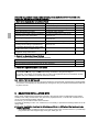
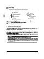
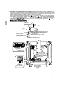
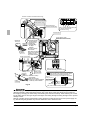
• Use the attached drain hose (1) and clamp (2).
• Insert the drain hose into the drain socket up to the base, and tighten the clamp securely within the portion
of a gray tape of the hose-inserted tip. Tighten the clamp until the screw head is less than 4 mm from the
hose.
• Wrap the attached large sealing pad (10) over the clamp and drain hose to insulate.
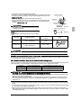
• Make sure that heat insulation work is executed on the following 2 spots to prevent any possible water
leakage due to dew condensation.
• Indoor drain pipe
• Drain socket
Clamp (2)
(attached)
Clamp (2)
(attached)
Large sealing pad (10)
(attached)
Drain hose (1)
(attached)
Tape (Gray)
4mm
Fig. 19
Fig. 20
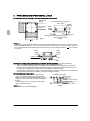
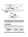
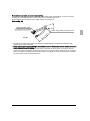
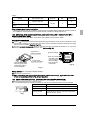
<PRECAUTIONS FOR DRAIN RAISING PIPING>
• Install the drain raising pipes at a height of less than 545 mm.
• Install the drain raising pipes at a right angle to the indoor unit and no more than 300 mm from the unit.
Hanger bracket
Ceiling slab
Adjustable
( 545)
205
1-1.5m
Clamp (2)
(attached)
750
300
Drain hose (attached)(1)
(mm)
Drain raising pipe
Raising section
Fig. 21
100mm
NOTE
• To ensure no excessive pressure is applied to the included drain hose (1), do not bend or twist when installing. (This may cause leakage.)
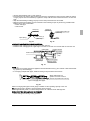
• If converging multiple drain pipes, install according to the procedure shown below.
Slope downwards at a
gradient of at least 1/100 to
prevent air pockets from forming
T-joint converging drain pipes
Fig. 22
Select converging drain pipes whose gauge is suitable for the operating capacity of the unit.
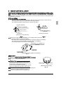
(2) After piping work is finished, check if drainage flows smoothly.
• Add approximately 1000 cc of water slowly from the air outlet and check drainage flow.
WHEN ELECTRIC WIRING WORK IS FINISHED
• Check drainage flow during cooling operation.
English
11