1
2010iP
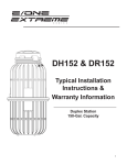
Simplex
Typical
Installation
Instructions
Simplex Station
700 L Capacity
Rev. 1
The 2010iP Simplex station is a
well-engineered system designed
to provide low-pressure sewer
service to individual residences or
buildings. Correct installation and
start-up of this equipment will
ensure proper operation.
This is a sewage handling pump
and must be vented in accordance
with national and local plumbing
codes. This pump is not to be
installed in locations classified as
hazardous. All piping and electrical
systems must be in compliance
with applicable standards, local
and national codes and to the
satisfaction of relevant authorities.
PRODUCT DESCRIPTION
The 2010ip Simplex station
consists of a grinder pump, tank,
pump alarm panel and connecting
power (supply) cable. The tank is a
polyethylene basin complete with a
gasket-sealed lid. Three lid styles
are available for the 2010iP
station (Figure 4). Sewage enters
the tank through the 100 mm DWV
uPVC (110.2 mm OD) (standard)
inlet pipe where it is ground into
fine particles by the grinder pump.
The in-line pumping mechanism
discharges the macerated sewage
to a pressure or gravity main, then
to a remote treatment site. The
pump is a semi-positive
displacement type capable of
operating at discharge pressures
up to 56 m TDH. Ample tank
storage capacity in conjunction
with integral level sensing controls
provides for economic, on-demand,
operation of the grinder pump.
ITEMS REQUIRED FOR
INSTALLATION
Prior to beginning installation, a
thorough review of these installation
instructions is recommended. This
will likely eliminate problems with
inconvenient piping and cable
locations or due to the
unavailability of materials or
equipment. In addition to the
components furnished with each
station, the following items will be
needed to support installation:
• Electrical supply in accordance
with the specification on the
pump nameplate.
• Bedding material (Section 2)
• Concrete ballast (Section 5)
• 100 mm DWV uPVC (110.2 mm
OD) inlet pipe (from residence or
building sewer) (Sections 4 & 7)
• PE100, 40mm OD, PN16,
SDR11 polyethylene discharge
pipe to force or gravity main
(recommended – Section 8)
• Compactable backfill material
(Section 11)
The following tools:
• 127mm (5”) dia. hole saw
• Pipe thread sealant (suitable
for materials being joined)
• Pipe wrenches
• Electric drill
• Common hand tools
INSTALLATION STEPS
The following instructions will
provide the necessary information
to properly install the grinder pump
station.
1. Station Unpacking
(Figure 1)
The station alarm panel, grinder
pump and tank are shipped to the
job site separately. Inspect the
tank (1) and ensure that it
sustained no damage during
shipment. Proper handling of the
polyethylene tank will ensure
reliable performance. Do not drop
the tank or roll it on its side. Only a
non-marring sling should be used
Fig. 1 - Station Components
3
NA0049P01 Rev. –
to lift the tank (see Lifting
Instructions, page 12). Ensure that
all lifting equipment is rated for the
load being lifted. Remove the tank
lid (2) and verify that the supply
cable cord grip (10) and the
discharge valve (4) are installed in
the tank. The inlet grommet (11)
was shipped loose with the tank.
The balance of the factory-provided
components was delivered with the
grinder pump unit. Inspect the
shipping cartons for signs of any
damage sustained during
shipment. Open the pump shipping
carton(s) and verify that the grinder
pump (6), pump stand (7),
discharge hose assembly (8),
equalizer (13), and supply cable (9)
are enclosed. Open the alarm
panel (12) shipping carton(s) and
ensure that alarm panel has
sustained no shipping damage. If
damage is suspected on any of the
components, do not proceed with
installation. Notify an Environment
One representative of any damage
discovered or any missing
components.
2. Site Excavation
(Figure 2)
Excavate a hole of sufficient
depth and width to accommodate
the tank, ballast, underground
piping and required backfill material
as well as providing adequate
working space for plumbing and
electrical connections. The base of
the excavated hole should be level
and prepared with proper bedding
material, such as gravel, in
accordance with the site engineer’s
requirements. The depth of the
excavation must be sufficient to
accommodate the bedding material
and tank burial. The station burial
depth depends on the specific
2010iP model being
installed. Figure 4 shows the
appropriate burial depth by model
(cover style) for each. The size,
shape and shoring requirements of
the excavation will be based on the
soil conditions and should be in
accordance with the site engineer’s
recommendation and safety
requirements.
3. Tank Installation
Improper handling of the tank
may result in damage and,
ultimately, failure of the station.
Care should be taken during lifting
and placement to prevent impacting
or otherwise damaging the tank. A
non-marring sling should be used
when lifting the tank (see Lifting
Instructions, page 12). Ensure that
the lifting sling is rated for the load
being lifted. Lifting chains or cables
should never be placed in direct
contact with the tank surfaces.
Place the tank on the level bed of
fill material in the excavated hole.
Orient the installed discharge
fitting, as required, to align it with
the existing or proposed discharge
piping path.
4. Inlet Pipe Location
A 100 mm uPVC inlet grommet
was provided with the station for
sealing the inlet pipe at the tank
wall. Other inlet pipe grommet
sizes are also available (Section 7).
The location of the tank inlet must
be determined to support final
positioning of the tank prior to
ballast installation. The inlet pipe
location corresponds with the
actual or projected point where the
Fig. 2 - Excavation and Ballast
NA0049P01 Rev. –
4
100 mm building sewer line
intersects the tank wall. The grade
of the inlet pipe and required burial
depth (per national and local code
requirements) must be accounted
for when determining the inlet
location. The supply cable path
should be considered when
selecting the inlet location (Figure
7 and Section 10). A 127 mm
diameter field penetration of the
tank wall is required to support
installation of the 100 mm
(standard) inlet grommet. This
penetration must not remove or
interfere with any of the structural
ribbing on the polyethylene tank.
The inlet grommet may be installed
in any of the allowable locations
shown in Figure 3. The inlet
penetration must be centered in
the location selected to prevent
interference with the tank ribbing.
Typical inlet installation will be on
one of the 200 mm diameter, raised
panels on the tank body. The
panels have been marked with a
series of locating lines to support
centering of the drilled penetration.
The selected elevation of the inlet
penetration must be in compliance
with national and local code
requirements. Any inlet installed in
the depressed panels between the
horizontal and vertical ribbing must
be centered within the panel to
provide adequate clearance for the
152 mm diameter flange on the
standard 100 mm inlet grommet
(Figure 3). Do not install inlet in
lower, tapered section of the tank.
Once the location of the inlet
penetration is selected, mark the
inlet center location on the tank
and position the tank to line up the
inlet location with the inlet pipe
path.
5. Ballast Installation
A concrete anchor is required
to prevent flotation of the
polyethylene tank when
groundwater is present. The volume
of concrete used must comply with
the site engineer’s requirements.
Recommended minimum ballast
volumes are presented in Chart 1 of
the Ballast Calculation page.
Ensure that the tank is properly
positioned in the excavation to
accomodate the marked inlet
location (Section 4) before pouring
the concrete ballast. Concrete
ballast should be cast in place
around the tank in the excavation.
Do not pour the concrete ballast
above the marked inlet pipe
location. If the ballast must be
poured above this level, proceed
with installation of the inlet piping
(Section 7) before pouring the
concrete. The inlet pipe must be
sleeved with a 200 mm tube prior to
pouring. The tank should be filled
with water, to a level above the
specified ballast height to prevent
shifting during the concrete pour.
Alternatively, precast concrete,
around the tank bottom, may be
used for ballast (Figure 2). Do not
pour ballast above the intended
inlet location. If this ballast method
is used, lifting hooks must be
anchored in the concrete to support
Fig. 3 - Allowable Inlet Locations
5
NA0049P01 Rev. –
subsequent handling of the tank.
The lifting hooks must be adequate
to support the combined weight of
the tank and concrete ballast, and
should be sized and installed in
accordance with the site engineer’s
recommendation. Place the
ballasted tank in the excavated
hole using the lifting hooks. Do not
lift by any of the tank surfaces if
precast ballast is utilized.
6. Venting
(Figure 4)
The 2010iP station is a
sewage handling pump and
requires ventilation for proper and
safe operation. The method of
station ventilation will vary
depending on the specific model
ordered. The vent location for each
model is shown in Figure 4. Do not
bury the station above the
appropriate burial line (by model)
indicated in Figure 4. Burial above
this level will result in blockage of
the integral cover vent system
provided on most 2010iP
models.
If the water level outside of the
station is expected to rise above
the surrounding grade (flooding), a
cover vent system cannot be used.
If flood conditions are expected, an
underground (lateral) vent system
and solid cover, as shown on the
2010iP 800 mm x 1900mm station,
must be used. Refer to
the E/One Lateral Vent Installation
Instructions (PA2114P01) for
information about underground
station venting. Consult the
factory if flood conditions are
possible where the station is to
be installed.
7. Inlet Installation
(Figure 5)
The station is supplied with a
standard grommet to accept a 100
mm DWV uPVC (110.2 mm OD)
sewer inlet pipe. The grommet is
self-sealing and does not require
the use of additional sealant or
adhesives. Verify that the grommet
supplied with the 201
station will accommodate the
selected inlet piping. Using a 127.0
mm (5”) hole saw, drill through the
polyethylene tank wall at the
marked inlet location (Section 4).
Remove any burrs or chips from the
drilled-hole edges.
Note: Other grommet sizes are
available upon request. Alternate
grommet sizes may require a
different diameter tank penetration.
Consult an E/One representative
before drilling the tank inlet if an
alternate grommet is required.
Install the supplied inlet
grommet in the drilled hole. Place a
mark on the inlet pipe about 90 mm
from the end that will enter the
tank. A bevel should be ground or
filed on the pipe end to aid in
installation through the grommet
(Figure 5). Clean the grommet and
pipe surfaces to remove any debris.
Apply a film of pipe soap or dish
soap to the outside surface of the
inlet pipe end and the inside of the
grommet. Insert the beveled pipe
end into the grommet and push the
inlet pipe into the tank until the 90
mm mark lines up with the
grommet’s outside edge. Inspect
Fig. 4 - Tank Installation
NA0049P01 Rev. –
6
dance with applicable standards,
local and national codes and to the
satisfaction of relevant authorities.
10b. Grinder Pump to Alarm
Panel (Figure 7)
Fig. 5 - Inlet Installation
the grommet flange on the outside
of the tank. The flange should be
flush against the tank wall and
completely visible when the pipe
and grommet are installed properly.
8. Tank Discharge Piping
Connection
(Figure 7)
Connect the tank discharge
piping to the threaded tank fitting.
The 1-1/4” BSP female thread on
the discharge fitting will
accommodate a variety of pipe
materials and fittings. Discharge
piping must be selected in
accordance with local and national
plumbing codes. If allowable, the
use of PE100, 40 mm OD, PN16,
SDR11 polyethylene pipe is
recommended. If polyethylene
discharge piping is used,
compression type fittings that
provide a smooth inner passage
should be utilized. It is
recommended that an isolation
valve and a redundant check valve
assembly (boundary kit) be
installed between the pump
discharge valve and the street main
on all installations. Never use a ball
type valve as a check valve. It is
recommended that the valves be
installed as close to the public
right-of-way (road reserve) as
possible. Check local codes for
applicable requirements.
CAUTION: Redundant check
valves on station laterals and antisiphon/check valve assemblies on
the grinder pump cores should not
be used as system isolation valves
during line tests.
9. Alarm Panel Mounting
Before proceeding, verify that the
supply voltage is the same as the
motor voltage shown on the grinder
pump nameplate. Determine the
location of the station alarm panel.
The alarm panel may be mounted
on a pole or directly on an outdoor
wall surface. The mounting location
selected must be visible from the
grinder pump station location and
provide general visibility to the
occupants of the building. The
panel’s audible alarm should be
easily heard by the occupants of
the building. An alarm device is
required on every installation, there
shall be no exceptions. Mount the
alarm panel to a wall or pole,
securing it by the mounting flanges
with four screws. Any penetrations
into the Environment One alarm
panel shall be undertaken in such a
way as to maintain the integrity of
the IP rating (NEMA 4X, IP 65).
10. Electrical Connection
10a. Supply Panel to E/One
Alarm Panel
Wiring of supply panel and Environment One alarm panel shall be
carried out per the wiring instructions provided with the specific
alarm panel provided and in accor7
The grinder pump station is
provided with a cable for
connection between the station
and the alarm panel. This cable is
referred to as the “supply cable.”
The supply cable is shipped
coiled, inside the grinder pump
shipping carton. Environment One
recommends the cable be located
within a suitable, rigid, heavy-duty
conduit. Minimum depth of the
cable shall be 500 mm. The cable
must be provided with adequate
mechanical protection and
identification per local and national
codes. The cable and protection
must be installed with adequate
allowance for ground movement
and expansion. All conduit shall
enter the alarm panel from the
bottom and shall be sealed to
maintain the integrity of the IP
rating. NOTE: Wiring must be
installed in compliance with
applicable standards, local and
national codes.
10c. Installing E/One Supply
Cable (Figure 8)
1) Open the lid of the station
and locate the supply cable
connector on the inside wall of the
tank. Loosen the nut on the
connector and feed the free end
(the end without the E/One EQD
housing) of the supply cable
through the connector from the
inside of the station. Pull the
supply cable out through the
connector until it hits the crimped
“stop” feature on the cable,
approximately 900 mm from the
EQD housing.
**IMPORTANT: All but 900 mm
of the cable must be pulled out of
the station, and the portion of the
cable between the EQD and the
molded in cable breather should be
secured in position using the
provided hangers to ensure that
NA0049P01 Rev. –
the pump functions properly (Figure
8). Do not leave excess cable in
the station.
2) Run the cable underground,
in a trench or tunnel, in suitable
conduit, to the location of the
E/One panel. Use care when
installing and burying the supply
cable. If the cable is cut or
otherwise damaged it may result in
a pump malfunction. Connections
made at the panel are shown in the
wiring diagram accompanying the
alarm panel.
3) Retighten the supply cable
connector nut. This connection
must be tight or ground water will
enter the station.
11. Tank Backfill
Proper backfill is essential to the
long-term reliability of the grinder
pump station. The choice of backfill
material is dependent upon the
local soil and groundwater
conditions and must be in
accordance with the site engineer’s
requirements. The recommended
method of backfilling is to surround
the unit to the burial level (indicated
on the cover shroud) with proper fill.
The backfill material shall be to the
satisfaction of the local relevant
authority. Backfill shall be free of
organic and compressible material
and shall be free of voids and
cavities. Compaction moisture
content shall generally be 1% dry
and 2% wet of the optimum
content. Backfill shall be
compacted to the minimum
standard dry density ratios,
AS1289, 95%. Clays and silts
(12% or more passing through
#200 (.075 mm) sieve) are not
suitable backfill for this or any
underground structure such as inlet
or discharge lines. If you are
unsure of the consistency of the
native soil, it is recommended that
a geotechnical evaluation of the
material be obtained before
specifying backfill. Another option
is the use of a flowable fill (i.e., low
slump concrete). This is
particularly attractive when
installing grinder pump stations in
augured holes where tight
clearances make it difficult to
ensure proper backfilling and
compaction with dry materials.
Flowable fills should not be
dropped with more than 1-1/4
meters between the discharge
nozzle and the bottom of the hole
because this can cause separation
of the constituent materials.
12. Grinder Pump Stand
Assembly (Figure 9)
Temporarily rest the grinder
pump on its side. Using a block of
Fig. 7 - Typical Station Installation
NA0049P01 Rev. –
8
Fig. 8 - Electrical Cables
wood or similar object, prop up the
lower pump end to allow installation
of the pump stand. Align the two
legs of each pump stand half with
two of the holes in the pump lower
end. Push the stand legs into the
pump lower end until the legs
bottom against the suction housing
surface. Repeat for the other stand
half. Turn the pump upright on the
installed stand.
13. Grinder Pump Installation
(Figure 10)
The grinder pump should
only be installed in the station
upon connection and
commissioning of the discharge
piping, connection of the inlet
piping to the building sewer,
and upon availability of pump
station power from the provided
alarm panel to support start-up
testing (see Section 14).
Prior to installing the grinder
pump in the tank, flush the inlet
pipe with water to force any
miscellaneous debris in the sewer
line into the tank. Heavy debris,
sand, clay, construction materials,
etc. should be removed from the
tank before installing the grinder
pump. The grinder pump was
supplied with all of the necessary
plumbing components to connect
the pump discharge to the tank
discharge valve.
1. Ensure that one slip nut and
one split ring are properly
located behind the raised bead
on each end of the discharge
hose.
2. Place one back-up ring and one
O-ring on each end of the
discharge hose assembly
between the raised bead and the
edge of the hose assembly.
Note that the molded groove in
the back-up ring is designed to
be placed adjacent to the rubber
O-ring.
3. Slide the straight, stainless steel
end of the discharge hose
assembly into the top of the
check valve assembly on the
grinder pump until the raised
bead contacts the check valve
housing. Both the O-ring and
back-up ring should slide into
the bore of the check valve
housing. The hose should be
oriented as shown in Figure 10
to support alignment with the
station discharge valve.
4. Secure the hose assembly to
the pump by tightening the slip
nut onto the check valve
housing. Overtightening the slip
nut may damage the check
valve. The slip nut should only be
tightened to ¼ to ½ turn beyond
hand-tight.
5. Using the pump lifting harness,
lower the grinder pump into the
tank until the pump stand rests
on the bottom surface of the
tank. Orient the pump in the
basin so that the curved end of
the discharge hose is aligned
with the discharge valve receiver.
6. Slide the curved, stainless steel
end of the discharge hose
assembly into the discharge
valve receiver until the raised
bead contacts the top of the
valve receiver. Both the O-ring
and back-up ring should slide
into the bore of the valve receiver.
7. Secure the hose assembly to
the discharge valve by tightening
the slip nut onto the valve
receiver. The slip nut should only
be tightened to ¼ to ½ turn
beyond hand-tight.
8. The valve handle should be left in
the “OFF” (horizontal) position
until system start-up testing is
Fig. 9 - Pump Stand Installation
9
NA0049P01 Rev. –
conducted.
After completing the plumbing,
proceed with connecting the pump
power cable. The grinder pump
power cable is supplied with the
mating half of the EQD connector.
Verify that the EQD O-ring is in
place on the grinder pump power
cord (Figure 8). Plug the pump
power cable into the supply cable
EQD connector. Note that the EQD
halves are “keyed” and the plug
connections can only be made one
way. Secure the EQD connection
by tightening the locking ring until it
stops. Using the provided hanging
hooks, secure the EQD and supply
cable to the cover shroud (Figure
8).
14. Start-Up Test Procedure
When the system is completely
installed, the station should be
checked to ensure proper
installation and reliable
performance.
should only be performed by
qualified personnel trained in the
safe operation of this equipment
and electrical system servicing.
1. Ensure that the electrical
power supplying the control
panel is “OFF”.
2. Ensure that the grinder pump
and alarm circuit breakers in
the alarm panel are in the
“OFF” position.
3. Perform Continuity Test
procedure in accordance with
the the appropriate section
(hard-wired or wireless) of the
Environment One grinder pump
service manual.
4. Turn “ON” the power to the alarm
panel from the building service
panel.
5. Using a test (volt) meter, verify
that the incoming panel voltage
is within 10% of the pump
nameplate voltage (for 240V
pump, voltage at panel must be
216V to 264V). If the voltage is
outside of this range, do not
continue with station start-up.
The voltage problem must be
corrected prior to proceeding.
START-UP TEST
The following test must be
performed prior to placing the
system in service:
1. Ensure all service and alarm
panel breakers are in the “OFF”
position.
2. Open the discharge valve in the
tank by swinging the valve
handle to the “ON” (vertical)
position.
3. Open any additional discharge
lines. Some installations may
have additional discharge line
valves before entering the street
main.
4. Fill the tank with water to
approximately 900 mm from the
bottom (approximately 280 L).
Shut off the fill water.
5. Turn “ON” power to the alarm
panel, from the building service
panel.
SYSTEM INSPECTION
Perform the following
inspections:
• Proper burial depth – the tank
should have been buried to the
burial level shown (Figure 4).
• Proper grading – the surrounding
soil should be graded down,
away from the station.
• Station supply cable – the
station supply cable must not be
exposed outside of the station.
Suitable conduit should be used.
Proper burial depth (500 mm)
shall be maintained.
• Alarm panel – ensure that the
alarm panel is properly mounted
and free of any damage. Verify
that the alarm panel has been
wired properly in accordance
with the wiring instructions
provided with the panel.
ELECTRICAL TESTS
The following electrical tests are
recommended prior to operating
the grinder pump station. These
tests require the use of appropriate
electrical test equipment and
NA0049P01 Rev. –
Fig. 10 - Grinder Pump Installation
10
6. Set the alarm circuit breaker in
the alarm panel to the “ON”
position.
7. Set the grinder pump circuit
breaker and the alarm circuit
breaker in the alarm panel to the
“ON” position. Once power is
turned on to the grinder pump
and alarm breakers:
• The red light and buzzer will
immediately turn on.
• The grinder pump should start
immediately.
• The red alarm lamp and buzzer
should switch off in
approximately 3 minutes.
• The pump should stop within
approximately an additional 2
minutes.
OPERATIONAL
ELECTRICAL TEST
The following electrical test is
recommended in conjunction with
the Start-Up Test of the grinder
pump station. This test requires the
use of appropriate electrical test
equipment and should only be
performed by qualified personnel
trained in the safe operation of this
equipment and electrical system
servicing.
1. The current to the grinder pump
should be measured in the alarm
panel, at the black wire
supplying the pump station
(supply cable).
2. Using an ammeter, measure the
current in the black wire while
the pump is operating.
3. The current should be between 5
amps and 6.7 amps.
4. Higher amperage indicates
higher discharge pressure.
Measured current in excess of
6.7 amps could indicate a
blocked or closed discharge line.
Correct any blockage problems
and confirm that the current is
within the acceptable range. If
the current remains outside of
the acceptable range, and no
discharge blockage is
detected, contact your local
Environment One or qualified
service representative.
11
NA0049P01 Rev. –
Lifting Instructions
FAILURE TO FOLLOW THESE INSTRUCTIONS COMPLETELY WILL VOID WARRANTY.
1. Transporting unit to
installation site:
2. No Ballast,
(to be poured in place):
If the station has been shipped
secured to a pallet, lift the unit from
the bottom during transportation.
Alternatively, lift the unit using 2
nylon straps wrapped around the
tank exterior, just below the cover
flange as shown below. Never roll
a station or move it on its side.
If the concrete anchor is to be
poured while the station is in place
lift the unit using 2 nylon straps
wrapped around the tank exterior
just below the cover flange, as
shown below. Keep station oriented
vertically to avoid any damage.
NA0049P01 Rev. –
12
3. Precast Ballast:
Never lift a station that has
ballast attached by any means
except the lifting hooks. The weight
of the concrete will damage the
station if you attempt to lift it from
any part of the station.
E/One Grinder Pump Station Ballast Calculations
A ballast, or concrete anchor, of proper volume and weight is required on most in-ground installations. The
following section explains how to arrive at the correct size ballast. The amount of ballast needed is equal to the
weight it would take to counterbalance the buoyant force exerted on a fully submerged station.
Installation Site Assumptions
1. Water table – under worst case, the ground water level is assumed to be at the finished grade level.
2. Backfill materials per these installation instructions.
3. The consulting engineer should perform a soil test to determine if the assumptions that have been made are
valid for the specific installation site. If the site conditions differ from these assumptions, then the consulting
engineer may revise the calculations as shown in this document.
Physical Constants
1. Density of Water = 1000 kg/m3
2. Density of Concrete (in air)= 2402 kg/m3
3. Density of Concrete (in water)= 1402 kg/m3
4. Density of Saturated Backfill = 1120 kg/m3
Procedure
A. Determine the buoyant force exerted on the station
1. Determine the buoyant force that acts on the grinder pump station when it is submerged in water.
2. Subtract the weight of the tank from the buoyant force due to the submerged tank to determine the net
buoyant force acting on the station.
B. Determine the ballast force exerted on the station
1. Determine the ballast force applied to the station from the concrete and saturated soil surrounding the
station.
C. Subtract the ballast force from the buoyant force
1. Note – if the installation site conditions are different from those listed above, the consulting engineer should
recalculate the concrete ballast.
Ballast Calculations
The following calculations are to outline the areas used to determine the volumes of the different materials for the
ballast. All sections referred to in the calculations are marked on the accompanying drawing.
Sample Calculation: 800 mm x 2100 mm Station
Volume of Station = .79 m3
Tank Weight = 75 kg
Station Height = 2.02 m
A. Buoyant Force
1. The buoyant force acting on the submerged 2010iP is equal to the weight of the displaced water for
the section of the tank that is submerged.
Fbuoyant = (density of water)(volume of station)
= (1000 kg/m3)(.79 m3)
= 790 kg
13
NA0049P01 Rev. –
E/One Grinder Pump Station Ballast Calculations
2. The net buoyant force acting on the station (Fnet-buoyant) is equal to the buoyant force (Fbuoyant) minus the weight
of the station tank.
Fnet-buoyant = 790 kg - 75 kg
= 715 kg
B. Ballast Force
1. Determine the volume of concrete & soil
Section I: Used To Determine The Volume Of Concrete
(Note: .691m = assumed, inside diameter of concrete ballast ring around tank bottom flange)
Volume = (Height)(Area)
π)((1.066 m)2 - (.691m)2)/4
= (.178 m)(π
= (.178 m )(.517 m2)
= .092 m3
Section II: Used To Determine The Volume Of Saturated Soil
(Note: .815 m = assumed, inside diameter of soil column around tank maximum diameter)
Volume = (Height)(Area)
π)((1.066 m)2 - (.815 m)2)/4
= (2.02 m - .178 m)(π
2
= (1.842 m)(.371 m )
= .683 m3
2. Determine the combined ballast
Ballast (total) = Ballast (concrete) + Ballast (saturated soil)
= (Vconcrete)(density concrete in water) + (Vsoil)(density saturated soil)
= (.092 m3)(1402 kg/m3) + (.683 m3)(1120 kg/m3)
= 128 kg + 765 kg
= 892 kg
C. Subtract the net buoyant force from the ballast force to determine the final condition
Final Condition = Ballast Force - Net Buoyant Force
= 892 kg - 715 kg
= 177 kg (excess ballast)
The approach outlined may be used to calculate the ballast requirements listed below.
Chart 1
GP Model
2010iP
.
Station
Volume
(m 3)
FNet
Bouyant
(kg)
Tank
Weight
(kg)
FBallast
(kg)
Volume
Concrete
(m 3)*
Weight
Concrete in
Air (kg)*
Minimum
Minimum
Diameter of Thickness of
Concrete
Concrete
Anchor (mm) Anchor (mm)
800 x 1900
.72
646
74
892
0.09
216
1,066
178
800 x 2000
.72
646
74
892
0.09
216
1,066
178
800 x 2100
.79
715
75
892
0.09
216
1,066
178
* Volume calculated is for minimum dimensions given. Minimum dimensions must be met or exceeded for
actual application.
NA0049P01 Rev. –
14
2010iP Simplex
2010iP Simplex BALLAST INFORMATION
(800 x 2100mm)
15
NA0049P01 Rev. –
WEBSITE www.ecoflow.co.nz
EMAIL [email protected]
AUCKLAND (Head Office)
CHRISTCHURCH
16 Piermark Drive, Albany
PO Box 300 249, Albany, Auckland 0752
TELEPHONE 09 447 1793
15 Anchorage Road
South Hornby, Christchurch 8042
TELEPHONE 03 349 2506