1
Operating Manual Reprint
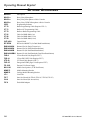
CONTROLS & CONNECTORS
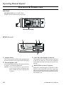
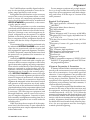
Front Panel
‚ƒ
•
†
„
…
POWER
A
ˆ ‰ Š
‡
• POWER Button
Press the button to turn the transceiver ON and
OFF.
‚ TX Indicator
This lamp glows red when the radio is transmitting.
ƒ BUSY Indicator
This lamp glows green when the channel is busy.
„ Liquid Crystal Display
The display include an 8-character alpha-numeric
section showing channel and group names, status and identity information, and error messages.
Additional indicators on the display show priority channel assignments and scan include / exclude selection.
This channel on
“HORN ALERT” List
† SQC Indicator
This lamp glows orange when incorrect position
at the setting of CE35.
‡ Programmable Function Button (PF button)
This button can be set up for special applications,
such as high/low power selection, monitor, dimmer, talk-around, and call alert function, as determined by your network requirements and programmed by your VERTEX STANDARD dealer.
ˆ VOLUME Knob
‰ EMERGENCY Microphone
This channel on “INTERCOM” List
Receiver Monitor
This channel on
“SCAN” List
This channel
on “OPTION”
List
Pressing these buttons changes the current group
(and displayed group number or name). Holding this button for more than 1/2 second causes
the function to repeat.
This knob sets the volume of the receiver.
This channel on
“SELECTABLE TONE” List
This channel on “PUBLIC
A DDRESS ” or “S PEAKER ”
List
… p/q Button
Channel Group
Number
The emergency microphone is located behind this
small slit. When the emergency feature is activated, this Microphone is enabled.
Š CHANNEL Selector Knob
This knob select the operating channel.
Programmable Function Button (PF button)
This button can be set up for special applications,
such as high/low power selection, monitor, dimmer, talk-around, and call alert function, as determined by your network requirements and programmed by your VERTEX STANDARD dealer.
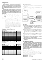
8 Character Alpha-numeric Display
This channel on “AUX A/B/C” List
VX-4000 VHF Service Manual
1-1