1
SiUS711114
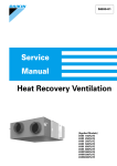
Service
Manual
Energy Recovery Ventilator
[Applied Models]
VAM 300GVJU
VAM 470GVJU
VAM 600GVJU
VAM1200GVJU
SiUS711114
Energy Recovery Ventilator
ED Reference
For items below, please refer to Engineering Data.
No.
1
2
Item
Specification
Option List
ED No.
EDUS711116
EDUS711116
Page
Remarks
P. 2
P. 49
1. Introduction ................................................................................................ iii
1.1 Safety Cautions ............................................................................................iii
1.2 Safety Symbols .......................................................................................... viii
Part 1 General Information
1. Model Names ..............................................................................................2
2. External Appearance...................................................................................2
3. Constructions ..............................................................................................3
Part 2 Operation
1. Operation ....................................................................................................6
1.1 Explanation for Systems............................................................................... 6
1.2 Operating the Energy Recovery Ventilator Using the Remote Controller of the
VRV-System Air Conditioner........................................................................ 8
Part 3 Maintenance
1. Maintenance (for a qualified service person only).....................................11
1.1 How to Clean the Air Filter ......................................................................... 11
1.2 How to Clean the Heat Exchanger Core .................................................... 14
Part 4 Control Functions
1. Control Functions ......................................................................................16
1.1 List of Control Functions............................................................................. 16
1.2 Explanation of Individual Functions............................................................ 17
1.3 Layout of switches on PCB ........................................................................ 24
Part 5 Service Diagnosis
1. Troubleshooting ........................................................................................27
1.1 Error Code Display ..................................................................................... 27
1.2 Overall Alarm.............................................................................................. 29
Table of Contents
i
SiUS711114
1.3
1.4
1.5
1.6
1.7
1.8
1.9
1.10
1.11
1.12
1.13
1.14
1.15
1.16
1.17
1.18
1.19
1.20
Overall Error ............................................................................................... 30
Indoor Air Thermistor Error......................................................................... 31
Outdoor Air Thermistor Error...................................................................... 32
Damper System Error (Alarm).................................................................... 33
Damper System Error (Alarm).................................................................... 35
Dedicated LCD Remote Controller............................................................. 36
Transmission Error between Remote Controller and Main Unit ................. 38
Transmission Error (Remote Controller) .................................................... 40
Transmission Error between Main Remote Controller and Sub Remote
Controller.................................................................................................... 41
Field Setting Error ...................................................................................... 42
Duplication of Centralized Remote Controller ............................................ 43
Main Unit PCB Abnormality........................................................................ 44
Dedicated LCD Remote Controller............................................................. 46
How to Check ............................................................................................. 47
Thermistor .................................................................................................. 48
Power Transformer..................................................................................... 49
Damper Motor ............................................................................................ 51
Check ......................................................................................................... 52
Part 6 Supplementary Explanation ................................................ 53
1. Service Mode ............................................................................................54
1.1 BRC1E71 ................................................................................................... 54
Part 7 Appendix
1. Wiring Diagram .........................................................................................57
1.1 VAM300GVJU / VAM470GVJU / VAM600GVJU ....................................... 57
1.2 VAM1200GVJU .......................................................................................... 58
ii
Table of Contents
SiUS711114
Introduction
1. Introduction
1.1
Safety Cautions
Cautions and
Warnings
Be sure to read the following safety cautions before conducting repair work.
The caution items are classified into “
Warning” and “
Caution”.
Warning Indicates a
potentially hazardous situation which, if not avoided, could result in death or serious injury.
Caution Indicates a potentially hazardous situation which, if not avoided, may result in minor or
moderate injury. It may also be used to alert against unsafe practices. Be sure to observe all the
safety caution items described below.
About the pictograms
This symbol indicates the item for which caution must be exercised.
The pictogram shows the item to which attention must be paid.
This symbol indicates the prohibited action.
The prohibited item or action is shown in the illustration or near the symbol.
This symbol indicates the action that must be taken, or the instruction.
The instruction is shown in the illustration or near the symbol.
After the repair work is complete, be sure to conduct a test operation to ensure that the
equipment operates normally, and explain the cautions for operating the product to the
customer.
1.1.1 Cautions Regarding Safety of Workers
Warning
Be sure to disconnect the power cable plug from the plug socket before
disassembling the equipment for repair.
Working on the equipment that is connected to the power supply may cause an
electrical shook.
If it is necessary to supply power to the equipment to conduct the repair or
inspecting the circuits, do not touch any electrically charged sections of the
equipment.
If the refrigerant gas is discharged during the repair work, do not touch the
discharged refrigerant gas.
The refrigerant gas may cause frostbite.
When disconnecting the suction or discharge pipe of the compressor at the
welded section, evacuate the refrigerant gas completely at a well-ventilated
place first.
If there is a gas remaining inside the compressor, the refrigerant gas or
refrigerating machine oil discharges when the pipe is disconnected, and it may
cause injury.
If the refrigerant gas leaks during the repair work, ventilate the area. The
refrigerant gas may generate toxic gases when it contacts flames.
The step-up capacitor supplies high-voltage electricity to the electrical
components of the outdoor unit.
Be sure to discharge the capacitor completely before conducting repair work.
A charged capacitor may cause an electrical shock.
Do not start or stop the air conditioner operation by plugging or unplugging the
power cable plug.
Plugging or unplugging the power cable plug to operate the equipment may
cause an electrical shock or fire.
iii
Introduction
SiUS711114
Warning
Be sure to wear a safety helmet, gloves, and a safety belt when working at a
high place (more than 6.56 ft.). Insufficient safety measures may cause a falling
accident.
In case of R-410A refrigerant models, be sure to use pipes, flare nuts and tools
for the exclusive use of the R-410A refrigerant.
The use of materials for R-22 refrigerant models may cause a serious accident
such as a damage of refrigerant cycle as well as an equipment failure.
Caution
Do not repair the electrical components with wet hands.
Working on the equipment with wet hands may cause an electrical shock.
Do not clean the air conditioner by splashing water.
Washing the unit with water may cause an electrical shock.
Be sure to provide the grounding when repairing the equipment in a humid or
wet place, to avoid electrical shocks.
Be sure to turn OFF the power switch and unplug the power cable when
cleaning the equipment.
The internal fan rotates at a high speed, and cause injury.
Be sure to conduct repair work with appropriate tools.
The use of inappropriate tools may cause injury.
Be sure to check that the refrigerating cycle section has cooled down enough
before conducting repair work.
Working on the unit when the refrigerating cycle section is hot may cause
burns.
Use the welder in a well-ventilated place.
Using the welder in an enclosed room may cause oxygen deficiency.
iv
SiUS711114
Introduction
1.1.2 Cautions Regarding Safety of Users
Warning
Be sure to use parts listed in the service parts list of the applicable model and
appropriate tools to conduct repair work. Never attempt to modify the
equipment.
The use of inappropriate parts or tools may cause an electrical shock,
excessive heat generation or fire.
If the power cable and lead wires have scratches or deteriorated, be sure to
replace them.
Damaged cable and wires may cause an electrical shock, excessive heat
generation or fire.
Do not use a joined power cable or extension cable, or share the same power
outlet with other electrical appliances, since it may cause an electrical shock,
excessive heat generation or fire.
Be sure to use an exclusive power circuit for the equipment, and follow the local
technical standards related to the electrical equipment, the internal wiring
regulations, and the instruction manual for installation when conducting
electrical work.
Insufficient power circuit capacity and improper electrical work may cause an
electrical shock or fire.
Be sure to use the specified cable for wiring between the indoor and outdoor
units. Make the connections securely and route the cable properly so that there
is no force pulling the cable at the connection terminals.
Improper connections may cause excessive heat generation or fire.
When wiring between the indoor and outdoor units, make sure that the terminal
cover does not lift off or dismount because of the cable.
If the cover is not mounted properly, the terminal connection section may cause
an electrical shock, excessive heat generation or fire.
Do not damage or modify the power cable.
Damaged or modified power cable may cause an electrical shock or fire.
Placing heavy items on the power cable, and heating or pulling the power cable
may damage the cable.
Do not mix air or gas other than the specified refrigerant (R-410A / R-22) in the
refrigerant system.
If air enters the refrigerating system, an excessively high pressure results,
causing equipment damage and injury.
If the refrigerant gas leaks, be sure to locate the leaking point and repair it
before charging the refrigerant. After charging refrigerant, make sure that there
is no refrigerant leak.
If the leaking point cannot be located and the repair work must be stopped, be
sure to perform pump down and close the service valve, to prevent the
refrigerant gas from leaking into the room. The refrigerant gas itself is
harmless, but it may generate toxic gases when it contacts flames, such as fan
and other heaters, stoves and ranges.
v
Introduction
SiUS711114
Warning
When relocating the equipment, make sure that the new installation site has
sufficient strength to withstand the weight of the equipment.
If the installation site does not have sufficient strength and if the installation
work is not conducted securely, the equipment may fall and cause injury.
Check to make sure that the power cable plug is not dirty or loose, then insert
the plug into a power outlet securely.
If the plug has dust or loose connection, it may cause an electrical shock or fire.
For unitary type
Be sure to install the product correctly by using the provided standard
only
installation frame.
Incorrect use of the installation frame and improper installation may cause the
equipment to fall, resulting in injury.
Be sure to install the product securely in the installation frame mounted on the For unitary type
window frame.
only
If the unit is not securely mounted, it may fall and cause injury.
When replacing the coin battery in the remote controller, be sure to disposed
of the old battery to prevent children from swallowing it.
If a child swallows the coin battery, see a doctor immediately.
Caution
Installation of a leakage breaker is necessary in some cases depending on the
conditions of the installation site, to prevent electrical shocks.
Do not install the equipment in a place where there is a possibility of
combustible gas leaks.
If the combustible gas leaks and remains around the unit, it may cause a fire.
Check to see if the parts and wires are mounted and connected properly, and
if the connections at the soldered or crimped terminals are secure.
Improper installation and connections may cause excessive heat generation,
fire or an electrical shock.
If the installation platform or frame has corroded, replace it.
Corroded installation platform or frame may cause the unit to fall, resulting in
injury.
Check the grounding, and repair it if the equipment is not properly grounded.
Improper grounding may cause an electrical shock.
vi
SiUS711114
Introduction
Caution
Be sure to measure the insulation resistance after the repair, and make sure
that the resistance is 1 M or higher.
Defective insulation may cause an electrical shock.
Be sure to check the drainage of the indoor unit after the repair.
Defective drainage may cause the water to enter the room and wet the furniture
and floor.
Do not tilt the unit when removing it.
The water inside the unit may spill and wet the furniture and floor.
Be sure to install the packing and seal on the installation frame properly.
For unitary type
If the packing and seal are not installed properly, water may enter the room and only
wet the furniture and floor.
1.2
Safety Symbols
Icons are used to attract the attention of the reader to specific information. The meaning of each
icon is described in the table below:
Icon
Type of
Information
Note
Description
Caution
Indicates a potentially hazardous situation which, if not avoided,
may result in minor or moderate injury. It may also be used to
alert against unsafe practices.
Warning
Indicates a potentially hazardous situation which, if not avoided,
could result in death or serious injury.
Reference
A reference guides the reader to other places in this binder or in
this manual, where he/she will find additional information on a
specific topic.
Indicates situations that may result in equipment or propertydamage accidents only.
Note:
Caution
Warning
vii
SiUS711114
Part 1
General Information
1. Model Names ..............................................................................................2
2. External Appearance...................................................................................2
3. Constructions ..............................................................................................3
1
General Information
SiUS711114
Model Names
1. Model Names
Type
300
470
600
1200
Model name
VAM300GVJU
VAM470GVJU
VAM600GVJU
VAM1200GVJU
2. External Appearance
VAM300GVJU
VAM470GVJU
VAM600GVJU
VAM1200GVJU
General Information
2
Constructions
SiUS711114
3. Constructions
VAM300GVJU
VAM470GVJU
VAM600GVJU
(1) Hanger bracket
(8) Heat exchanger core
It exchanges heat (temperature and
humidity) from indoors with the air
taken in from outdoors, changes the
outside air to the same condition as
indoors and then brings it indoors.
(7) Service cover
(2) Duct connecting flange
(6) Control box
(3) Exhaust fan
(4) Air filter
(9) Nameplate
(5) Damper
Important
Sometimes when first using the unit, the
odor of the heat exchanger core may be
noticeable, but it is not harmful. The odor
will gradually go away as the unit is used.
(10) Supply air fan
(11) Remote controller
(Optional accessory)
(15) Service space
for the air filter,
the heat
exchanger core
and control box
(14) OA
(Outdoor air)
[Fresh air from
outside]
(17) SA
(Supply air)
[Supply air to
inside]
(13) EA
(Exhaust air)
[Exhaust air to
outside]
(16) RA
(Return air)
[Return air
from inside]
(12) Damper motor
3
General Information
SiUS711114
Constructions
VAM1200GVJU
(3) Exhaust fan
(1) Hanger bracket
(7) Service cover
(2) Duct connecting
(9) Nameplate
(6) Control box
(10) Supply air fan
(5) Damper
(4) Air filter
(8) Heat exchanger cores
It exchanges heat (temperature and humidity) from
indoors with the air taken in from outdoors, changes
the outside air to the same condition as indoors and
then brings it indoors.
Important
(11) Remote controller
(Optional accessory)
Sometimes when first using the unit, the
odor of the heat exchanger core may be
noticeable, but it is not harmful. The odor
will gradually go away as the unit is used.
(15) Service space
for the air filter,
the heat
exchanger core
and control box
(14) OA
(Outdoor air)
[Fresh air
from outside]
(17) SA
(Supply air)
[Supply air
to inside]
(13) EA
(Exhaust air)
[Exhaust air
to outside]
(16) RA
(Return air)
[Return air
from inside]
General Information
(12) Damper motor
4
SiUS711114
Part 2
Operation
1. Operation ....................................................................................................6
1.1 Explanation for Systems............................................................................... 6
1.2 Operating the Energy Recovery Ventilator Using the Remote Controller of
the VRV-System Air Conditioner .................................................................. 8
5
Operation
SiUS711114
Operation
1. Operation
1.1
Explanation for Systems
This product is operated differently depending on the system configuration.
For the operation of the remote controller for indoor unit and centralized control equipment, refer to
the instruction manual provided with each unit.
1.1.1 Independent System
Interlocking System with VRV or SkyAir System
SYSTEM
•
ERV
ERV
•
Independent system
Remote controller
2-wire cord
(field supply)
•
•
•
ERV
VRV
1-group linked
operation
system
•
•
Remote Remote
controller controller
•
Interlocking
system with
VRV or SkyAir
system
Multi-group (2
or more) linked
operation
system
VRV
VRV
Group 1
Group 2
•
Standard method
Up to 16 units can be controlled with the
remote controller. (A system with 2
remote controls can be created in the
main/sub setting.)
All ERV operations can be used and
indicated.
Operation monitor output and humidifier
operation are possible using the Adaptor
PCB.
Remote control cord should be field
supply. (Maximum cord length: 1640 ft.)
A combined total of up to 16 air
conditioners and the ERV can be
controlled.
The ERV mode can be operated
independently when air conditioners are
not being used.
Using the field setting of the remote
controller for air conditioners, various
settings such as pre-cool/pre-heat
reservation ON/OFF, ventilation rate,
ventilation mode, etc.
Since all VRV units are connected to a
single line in view of installation, all VRV
units are subjects for operation.
If there are problems operating all VRV
units, do not use this system.
Remote controller Remote controller
VRV
Group 3
Remote controller
VRV
Group 4
Remote controller
ERV
Note:
(1) Adaptor PCB: KPR50-2; Installation box for adaptor PCB: KRP50-2A90
(2) Operation of 2 or more group is not possible with a direct duct connection as below.
(3) The direct duct connection can also be selected for 1-group linked operation system.
SYSTEM
ERV
VRV
Direct duct connection system
Duct
Remote controller Remote controller
Operation
Standard method
• The ERV operates only when the air
conditioner fan is ON.
• When the air conditioner is not being
used, the ERV can be operated in
circulation or ventilation modes.
• Other specifications are the same as
those of the standard system.
6
Operation
SiUS711114
1.1.2 Centralized Control System (VRV System)
SYSTEM
VRV
“All”/individual
control system
VRV
Remote controller Remote controller
VRV
Standard method
• Use of the ON/OFF controller, Adaptor
PCB for remote control or Schedule timer
Adaptor PCB for
enables centralized control of the entire
remote control,
system. (maximum of 64 groups)
Schedule timer, • The ON/OFF controller can turn ON or
ON/OFF
OFF the individual units.
controller
• The schedule timer and ON/OFF
ERV
controller can be used together.
However, the Adaptor PCB for remote
control cannot be used with another
centralized control equipment.
VRV
ERV
Remote controller Remote controller
Centralized
control system
Centralized
control equipment
Zone 1
VRV
Zone control
system
VRV
Remote
controller
ERV
• Use of the centralized control equipment
enables zone control via the centralized
control line. (maximum of 64 zones)
• The centralized control equipment
displays the “Filter” indication and
abnormality warnings, and enables
resetting.
• The centralized control equipment allows
ventilation operation for each zone
independently.
Remote
controller
Zone 2
ERV
Caution
7
ERV
ERV
(1) Adaptor PCB: KRP50-2, Schedule timer: DST301BA61, ON/OFF controller: DCS301C71,
Central remote controller: DCS302C71
Operation
SiUS711114
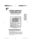
1.2
Operation
Operating the Energy Recovery Ventilator Using the
Remote Controller of the VRV-System Air Conditioner
Remote Controller for VRV
BRC1E71
1
11
4, 5, 6, 7 9
Mode
8
On/Off
Menu
OK
Fan
Speed
2
Cancel
3
10
1. Operation mode selector button
2. Fan speed control button
3. Menu/OK button
4. Up button
5. Down button
6. Right button
7. Left button
8. On/Off button
9. Operation lamp
10. Cancel button
11. LCD (with backlight)
Functions other than basic operation items (i.e., On/Off, Operation mode selector, Fan
speed control, and temperature set point) are set from the menu screen.
Note:
•
•
•
Do not install the remote controller in places exposed to direct sunlight, otherwise the LCD will
be damaged.
Do not pull or twist the remote controller wire, otherwise the remote controller may be damaged.
Do not use objects with sharp ends to press the buttons on the remote controller, otherwise
damage may result.
1. Operation mode selector button
• Press this button to select the operation mode of your preference.
Available modes vary with the indoor unit model.
2. Fan speed control button
• Press this button to select the fan speed of your preference.
Available fan speeds vary with the indoor unit model.
Operation
8
Operation
SiUS711114
3. Menu/OK button
• Used to indicate the main menu.
For details, refer to the operation manual attached to the remote controller.
• Used to enter the selected item.
4. Up button
• Used to raise the set point.
• The item above the current selection will be highlighted.
(The highlighted items will be scrolled continuously when the button is continuously
pressed.)
• Used to change the selected item.
5. Down button
• Used to lower the set point.
• The item below the current selection will be highlighted.
(The highlighted items will be scrolled continuously when the button is continuously
pressed.)
• Used to change the selected item.
6. Right button
• Used to highlight the next items on the right-hand side.
• Each screen is scrolled in the right-hand direction.
7. Left button
• Used to highlight the next items on the left-hand side.
• Each screen is scrolled in the left-hand direction.
8. On/Off button
• Press this button and system will start.
• Press this button again to stop the system.
9. Operation lamp (Green)
• This lamp illuminates solid during normal operation.
• This lamp blinks if an error occurs.
10. Cancel button
• Used to return to the previous screen.
11. LCD (with backlight)
• The backlight will be illuminated for approximately 30 seconds by pressing any button.
• If 2 remote controllers are used to control a single indoor unit, only the controller to be
accessed first will have backlight functionality.
9
Operation
SiUS711114
Part 3
Maintenance
1. Maintenance (for a qualified service person only).....................................11
1.1 How to Clean the Air Filter ......................................................................... 11
1.2 How to Clean the Heat Exchanger Core .................................................... 14
Maintenance
10
Maintenance (for a qualified service person only)
SiUS711114
1. Maintenance (for a qualified service person only)
Warning
•
•
•
•
Caution
•
•
•
1.1
ONLY A QUALIFIED SERVICE PERSON IS ALLOWED TO PERFORM MAINTENANCE.
BEFORE SERVICING TURN OFF ALL POWER SUPPLY.
To clean or do maintenance on the ERV, be sure to stop operation and turn the power switch
OFF. It may cause electric shock or injury.
Do not wash the ERV with water.
Doing so may result in an electric shock.
Use gloves when cleaning.
Cleaning without gloves may cause injury.
Watch your step.
Use caution, as this requires working in high places.
Do not use benzene or thinner to clean the outside surfaces of the unit.
This may cause cracks, discoloration or machine trouble.
How to Clean the Air Filter
Clean the air filter when the display shows the message “Time to clean filter” at the bottom.
It will display that it will operate for a set amount of time.
CLEANING FREQUENCY
AT LEAST ONCE EVERY YEAR
(FOR GENERAL OFFICE USE)
(CLEAN THE FILTER MORE FREQUENTLY IF NECESSARY.)
• Increase the frequency of cleaning if the unit is installed in a room where the air is extremely
contaminated.
• If the dirt becomes impossible to clean, change the air filter (The replacement air filter is
optional).
1. Remove the service cover.
Go into ceiling through the inspection hatch, remove a fixture of service cover and take it off.
VAM300GVJU ~ 600GVJU
(1) Service cover
(2) Fixture
(3) Hanger
VAM1200GVJU
(1) Service cover
(2) Fixture
(3) Hanger
11
Maintenance
SiUS711114
Maintenance (for a qualified service person only)
2. Remove the air filter.
Take out from the heat exchanger cores.
VAM300GVJU ~ 600GVJU
(1) Heat exchanger
core (2 pcs.)
(2) Handle
(3) Rail
(4) Air filter
VAM1200GVJU
(1) Heat exchanger
core (4 pcs.)
(2) Handle
(4) Air filter
(3) Rail
3. Clean the air filter.
Use a vacuum cleaner A) or wash the air filter with water B).
A) Using a vacuum cleaner
B) Washing with water
When the air filter is very dirty, use a soft brush and neutral detergent.
After cleaning, remove water and dry in the shade.
Note:
•
•
•
Maintenance
Do not wash the air filter with hot water of more than 122°F, as doing so may result in
discoloration and/or deformation.
Do not expose the air filter to fire, as doing so may result in burning.
Do not use gasoline, thinner or other organic solvents.
This may cause discoloration or deformation.
12
Maintenance (for a qualified service person only)
SiUS711114
4. Fix the air filter.
If the air filter is washed, remove water completely and allow to dry for 20 to 30 minutes in
the shade. When dried completely, install the air filter back in place.
Note:
•
Be sure to install the air filter after servicing.
(Missing air filter causes clogged heat exchanger core.)
The air filter is an optional item and the replacement is available.
5. Put the service cover back securely in place.
To reset the filter indicator on the remote controller,
press Menu/OK button and select “Reset Filter Indicator”
on the main menu screen.
Consult your dealer if you want to change the time setting for when the filter sign goes on.
Note:
13
•
Do not remove the air filter except when cleaning.
Breakdown may occur.
Maintenance
SiUS711114
1.2
Maintenance (for a qualified service person only)
How to Clean the Heat Exchanger Core
CLEANING FREQUENCY
AT LEAST ONCE EVERY 2 YEARS
(FOR GENERAL OFFICE USE)
(CLEAN THE CORE MORE FREQUENTLY IF NECESSARY.)
Warning
•
Replace the heat exchanger core if you find that the knob of the heat exchanger core is
damaged or is deteriorated when cleaning.
There is falling danger.
1. Remove the service cover.
2. Remove the air filter.
3. Take out the heat exchanger cores.
Pull out the air filter and then pull out the 2 heat exchanger cores.
4. Use a vacuum cleaner to remove dust and foreign objects on the surface of the heat
exchanger core.
Caution
(During Operation)
•
•
Use the vacuum cleaner equipped with a brush on the tip of the suction nozzle.
Lightly contact the brush on the surface of the heat exchanger core when cleaning.
(Do not crush the heat exchanger core while cleaning.)
•
Do not clean touching strongly with a vacuum cleaner. This may crush the mesh of the heat
exchanger core.
Never wash the heat exchanger core with water.
Have your dealer professionally clean the filter if it is very dirty.
•
•
5. Put the heat exchanger core on the rail and insert it securely in place.
6. Install the air filter securely in place.
7. Install the service cover securely in place.
Caution
Maintenance
•
Always use the air filter.
If the air filter is not used, the heat exchanger core will be clogged, possibly causing poor
performance and subsequent failure.
14
SiUS711114
Part 4
Control Functions
1. Control Functions ......................................................................................16
1.1 List of Control Functions............................................................................. 16
1.2 Explanation of Individual Functions............................................................ 17
1.3 Layout of switches on PCB ........................................................................ 24
15
Control Functions
SiUS711114
Control Functions
1. Control Functions
1.1
List of Control Functions
Classification
Function name
1. Basic functions
1.1 Ventilation
(functions related to operation control
basic performance) function
1.2 Abnormality
control function
2. Additional
2.1 Ventilation
functions
mode changeover
function
2.2 Automatic
ventilation
operation function
2.3 Ventilation
capacity
changeover
function
2.4 Humidifier
operation control
function
2.5 Pre-cool/preheat function
2.6 Fresh-up
function
2.7 Filter sign
function
3. System control
3.1 Remote
functions
controller function
3.2 Group function
3.3 Air conditioner
link function
3.4 Power ON
operation function
4. Other support
functions
Note:
Control Functions
3.5 External link
operation function
3.6 Centralized
control function
3.7 Timer function
4.1
Troubleshooting
function
4.2 Field setting
function
Outline of function
Controls supply air fan motor, exhaust air fan motor and
damper motor.
Detects abnormalities in thermistor, damper motor and
data transmission to prevent errors.
Operates equipment in selected ventilation mode (total
heat exchange, normal, automatic).
Selects the most suitable ventilation mode by controlling
damper motor according to temperature controller mode,
temperature setting and thermistor data.
Operates equipment at set airflow rate.
Controls humidifier output based on temperature
controller judgement. Note 1
Prevents equipment operation for a preset time (set time)
after air conditioner is turned ON.
Sets motor tap so that supply air fan airflow rate is larger
than exhaust air fan airflow rate.
Stores cumulative operation hour data and turns ON air
filter cleaning indicator.
Operates equipment according to instructions from
remote controller.
Operates 2 or more units based on instructions from
single remote controller.
Follows air conditioner ON/OFF instructions.
Operates equipment when power is turned ON.
Turns equipment ON and OFF according to external link
terminal signal (no-voltage contact a).
Allows remote control operation by centralized control
equipment.
Turns equipment ON and OFF at set time.
Displays error codes to indicate locations of error.
Allows initial setting from LCD remote controller.
Note 1
Requires optional humidifier and optional printed circuit board (KRP50-2: Wiring adaptor for remote
contact).
16
Control Functions
1.2
SiUS711114
Explanation of Individual Functions
1.2.1 Ventilation Operation Control
Controls ventilation fan motors (supply and exhaust air fans) and damper motor.
1) Normal operation
Operation chart
Remote controller
indication
Energy recovery
ventilator
Cleaning
Operation time
Ventilation fan motor
Damper motor
(ventilation mode)
Operation lamp
Filter sign
reset
Stop
Normal ventilation
mode selection
ON
OFF
ON
Total heat
exchange
ventilation
Total heat exchange ON
Normal ventilation
ventilation
ON
ON
Filter sign indicator
2) Direct duct connection with air conditioner
Operation chart
Air conditioner
Operation
ON/OFF
Operation
Fan motor
ON
Normal ventilation
mode selection
Air conditioner
fan OFF
Air conditioner
fan ON
Remote controller
indication
Energy recovery
ventilator
OFF
Note:
17
Ventilation fan motor
Damper motor
(ventilation mode)
ON
Total heat
exchange
ventilation
OFF
ON Normal
ventilation
OFF
Total heat
exchange
ventilation
10 sec
ON
Normal ventilation
Operation lamp
Lamp
ON
Direct duct connection setting can be made in VRV system or using field setting mode of Energy
recovery ventilator LCD remote controller.
Control Functions
SiUS711114
Control Functions
1.2.2 Pre-cool/Pre-heat
Pre-cool/pre-heat operations require the following conditions.
1. System
Pre-heat operation is possible only in air conditioner linked system (1 group, 2-group link).
Check the system first.
2. Energy recovery ventilator setting
Set Pre-heat ON/OFF to ON.
Pre-cool/pre-heat On/OFF setting can be made in air conditioner or using field setting mode of
LCD remote controller of Energy recovery ventilator. (Pre-cool time can be set between 30 and
60 min., and pre-heat time can be set between 30 and 150 min.)
3. Others
a) Energy recovery ventilator must be in non-operating condition for 2 consecutive hours or
more prior to pre-cool/pre-heat operation.
b) Temperature control mode of the air conditioner must be set to Cool, Heat or Dry.
Energy recovery
ventilator
Air conditioner
Operation
Normal ventilation Pre-cool/pre-heat
mode selection
time over
ON/OFF
Operation
OFF
Ventilation fan motor
Remote controller
indication
Control Functions
ON
Pre-cool/pre-heat ventilation
Damper motor
(ventilation mode)
Total heat exchange ventilation
Note:
Stop
Operation lamp
Lamp
ON
Operation standby
indication
Lamp
ON
ON
Normal ventilation
Total heat
exchange
ventilation
Operation standby indication is displayed only on LCD remote controller of Energy recovery
ventilator.
18
Control Functions
SiUS711114
1.2.3 Cold Area Mode
Stops or lowers ventilation airflow during defrosting operation and compressor non-operating
condition when equipment in heating mode, thus reducing heating load and cold air draft.
Operation chart (in heating operation only)
Air conditioner
Operation
ON/OFF
Operation
Fan motor
ON
Normal ventilation
mode selection
Defrosting operation
or compressor in
Non-defrosting operation or
non-operation
compressor in operation
Remote controller
indication
Energy recovery
ventilator
OFF
Note:
10 sec
Ventilation fan motor
ON
OFF
ON
OFF
ON
OFF or lower
Damper motor
(ventilation mode)
Total heat
exchange
ventilation
ON Normal
ventilation
Total heat
exchange
ventilation
ON
Normal ventilation
Operation lamp
Lamp
ON
Cold area mode can set using remote controller for air conditioner or field setting mode of LCD
remoter controller of Energy recovery ventilator.
Protection Control
Operation Control in Cold Climates
To operate the unit at low outdoor air temperatures, control the air supply fans and the exhaust fans
as shown below for equipment protection.
Normal operation
Models applicable to outdoor air
temperatures of 5˚F at minimum
Outdoor air temperature < 14°F
Outdoor air temperature > 17.6°F
Air supply fan ON for 45
min., OFF for 15 min.
Outdoor air temperature < 5°F
Outdoor air temperature > 8.6°F
Air supply fan stop (∗)
Exhaust fan stop (∗)
1.2.4 Air Conditioner Link Operation
Link system enables simultaneous ON/OFF operation of Energy recovery ventilator and air
conditioner (VRV system, SkyAir).
1) 1 group link control
Allows simultaneous ON/OFF from remote controller for air conditioner.
Allows independent operation of Energy recovery ventilator from VRV system remote controller
during interim periods (not possible when direct duct connection is used).
VRV system
Remote
controller for
air conditioner
19
Control Functions
SiUS711114
Control Functions
2) Link control of 2 or more groups (zone link)
Energy recovery ventilator can be operated when 1 or more air conditioners are operating.
Allows independent operation of Energy recovery ventilator from VRV-system remote controller
during interim periods (direct duct connection is not allowed in this system).
Group
1
Group
2
Group
3
Remote controller Remote controller Remote controller
for air conditioner for air conditioner for air conditioner
Adaptor PCB for
remote control
(KPR2A61)
Note:
Control Functions
With Super Wiring, units of different outdoor systems can be linked in operation.
20
Control Functions
SiUS711114
1.2.5 Field Setting, Service Mode
1. Field setting
Used for initial setting of Energy recovery ventilator.
2. Service mode
Used for confirmation of unit Nos. in the group and reallocation of unit Nos.
List of Settings
: Factory setting
Mode No.
FIRST
Group Individual CODE
NO.
settings settings
0
1
2
17
27
3
4
SECOND CODE NO. (NOTE 1)
Description of Setting
Filter cleaning time setting
Night-time free cooling
operation start time (after other
air conditioners operating
together with the unit have been
stopped)
Pre-cool/pre-heat ON/OFF
setting
Pre-cool/pre-heat time setting
Fan speed initial setting
Yes/No setting for direct duct
connection with VRV system
5
7
8
9
0
1
2
3
18
28
4
7
8
9
21
01
02
03
04
05
06
Approx.
2500
hours
Approx.
1250
hours
No
counting
–
–
–
OFF
2 hours
4 hours
6 hours
8 hours
–
OFF
ON
–
–
–
–
60 min.
–
–
–
–
–
–
–
–
–
–
–
30 min.
45 min.
Normal Extra high
No duct With duct
(Airflow (fan OFF)
setting)
Setting for cold areas (Fan
No duct
operation selection for heater
–
–
Fan OFF
Fan L
thermo. OFF)
Centralized Individual
–
–
Centralized/individual setting
Centralized zone interlock
No
Yes
–
–
setting
Pre-heat time extension setting
0 min.
30 min.
60 min.
90 min.
Priority
on
Last
Priority on
External signal JC/J2
–
command external
operation
input
Setting for direct Power ON
Auto restart setting
External damper operation
Indication of ventilation mode/
Not indication
With duct
Fan OFF
Fan L
–
–
–
–
–
–
–
–
OFF
OFF
–
ON
–
–
–
–
ON
–
–
–
–
–
ON
–
–
–
No
Indication
–
–
–
–
Indication
No
No
–
–
Fresh up air supply/exhaust
Indication Indication Indication Indication
setting
Supply
Exhaust
Supply
Exhaust
–
–
External input terminal function
Overall
Overall
Forced
Fan
forced
Airflow
selection (between J1 and JC) Fresh up
alarm
error
OFF
OFF
increase
KRP50-2 output switching
Fan
–
–
–
–
selection (between 1 and 3)
ON/OFF Abnormal
Preceding Preceding
Electric heater setting
No delay No delay ON, OFF ON, OFF
–
–
delay
delay
“Fresh up” ON/OFF setting
OFF
ON
–
–
–
–
19
29
8
1a
–
0
Note:
1. The settings are applied to the entire group, but if the mode No. individual settings is selected, the
settings can be applied to individual unit. However, it is only possible to check any changes made to
individual setting in individual mode. (For group control, the changes are made but the display remains
as it was when shipped from the factory.)
2. Do not set anything not shown above. If the applicable functions are not available, they will not be
displayed.
3. Group number setting for centralized controller
(1) Mode No. 00: Group controller
(2) Mode No. 30: Individual controller
Regarding the setting procedure, refer to the section “Group number setting for centralized control”
in the operating manual of either the ON/OFF controller or the central controller.
Control Functions
SiUS711114
Control Functions
1.2.6 External Damper Operation (FIELD SUPPLY)
Explanation of
Functions
Intake of outdoor air can be prevented when ERV is switched OFF if this damper is incorporated in
the system.
1. The PCB of the ERV unit supplies power for an external damper.
Control
box
Air
discharge
grille
18 in.
Inspection
hatch
External damper
(field supply)
Thermal
insulation
OA (Outdoor air
from outside)
Round shape hood
EA (Exhaust air
to outside)
Air suction
grille
PCB
ERV unit
External damper
(field supply)
• Power supply is turned ON when the ERV unit starts
operating.
Power supply is turned OFF when the ERV unit is
switched OFF.
Power supply voltage
Connected load capacity
208V
230V
0.5A or less
Required setting changes for switchover to X15A output
(see below for details)
Control Functions
22
Control Functions
Essential Wiring
SiUS711114
Connect one end of the harness to X15A on the PCB and the other end to the harness leading to
the damper via a connector such as a closed connector.
Control box cover
Open
this way
Transmission
wiring
Screws
To External
damper
Power
supply
wiring
Control box
Interior
Harness
(AWG20:
accessory)
Closed
connector
(field supply)
Electric
component
mounting
base
X15A
PCB
Clamp
(accessory)
With regard to a closed connector, select one that suits the wire size.
Secure the harness with the other wires by using the clamp.
Essential Setting
Changes
23
To make the X15A output available, change the field setting by the remote controller as below.
Mode No.: 18 (group control) or 28 (individual control)
FIRST CODE NO.: 3
SECOND CODE NO.: 03
Control Functions
SiUS711114
1.3
Control Functions
Layout of switches on PCB
1.3.1 PCB
Layout of switches on PCB
<VAM300GVJU, VAM470GVJU, VAM600GVJU>
Factory
setting
Factory
setting
Do not change the
switch setting
1.
2.
3.
4.
<VAM1200GVJU>
Do not change the
switch setting
∗
Transformer
Secondary
Primary
Connector for supply air fan
motor
5. Connector for exhaust fan
motor
6. Connector for damper
motor
7. Power supply
8. Terminal block
9. Connector for KPR50-2
10. Connector for limit switch
∗
11. Connector for indoor air
thermistor
12. Connector for outdoor air
thermistor
13. Selector switch
14. Terminals for remote
controller
15. Terminals for centralized
control
16. Terminals for no-voltage
external input
17. Factory setting
C: 3P034928-7Q
SS1 has already been set to “NOR” at factory.
The unit will not run if the setting is changed.
Control Functions
24
Control Functions
SiUS711114
1.3.2 Function of main connection terminal
Input from outside
Centralized remote controller
Remote controller
Power supply
Terminal No.
25
Contents of function
Single phase 208 – 230 V 60Hz
Power supply and ground terminal
L N
TeS1
Connection terminal for remote controller for
Energy recovery ventilator.
This terminal is used to receive information of the
indoor unit for interlocked operation.
P1 P2
This terminal is used to receive information when
centralized controller is connected.
F1 F2
Between terminal no. (J1) ~ (JC)
Used for “fresh up operation” by external input.
Between terminal no. (J2) ~ (JC)
Used for Operation / Stop by external input.
J1 J2 JC
Control Functions
SiUS711114
Part 5
Service Diagnosis
1. Troubleshooting ........................................................................................27
1.1
1.2
1.3
1.4
1.5
1.6
1.7
1.8
1.9
1.10
1.11
1.12
1.13
1.14
1.15
1.16
1.17
1.18
1.19
1.20
Service Diagnosis
Error Code Display ..................................................................................... 27
Overall Alarm.............................................................................................. 29
Overall Error ............................................................................................... 30
Indoor Air Thermistor Error......................................................................... 31
Outdoor Air Thermistor Error...................................................................... 32
Damper System Error (Alarm).................................................................... 33
Damper System Error (Alarm).................................................................... 35
Dedicated LCD Remote Controller............................................................. 36
Transmission Error between Remote Controller and Main Unit ................. 38
Transmission Error (Remote Controller) .................................................... 40
Transmission Error between Main Remote Controller and
Sub Remote Controller............................................................................... 41
Field Setting Error ...................................................................................... 42
Duplication of Centralized Remote Controller ............................................ 43
Main Unit PCB Abnormality........................................................................ 44
Dedicated LCD Remote Controller............................................................. 46
How to Check ............................................................................................. 47
Thermistor .................................................................................................. 48
Power Transformer..................................................................................... 49
Damper Motor ............................................................................................ 51
Check ......................................................................................................... 52
26
Troubleshooting
SiUS711114
1. Troubleshooting
1.1
Error Code Display
Operation
1
• If an error occurs, either one of the following
items will blink in the basic screen.
“Error: Push Menu button”
∗ The operation lamp will blink.
“Warning: Push Menu button”
∗ The operation lamp will not blink.
• Press Menu/OK button.
Operation
lamp
2
• The error code will blink and the service
contact and model name or code may
appear.
• Notify your Daikin dealer of the Error code
and model name or code.
List of error codes of Remote controller of the ERV-system
(The error codes displayed on remote controller are with two digits and not with four digits.)
Error Code
60
64
65
6A
6A
88
U5
U5
U8
UA
UC
UE
Description
Reference page
Overall alarm
Overall error
Indoor air thermistor error
Outdoor air thermistor error
Damper system error (Alarm)
Damper system error (Alarm)
29
30
31
32
33
33
Dedicated LCD remote controller
Transmission error between remote controller and main unit
Transmission error (Remote controller)
Transmission error between main remote controller and sub remote
controller
Field setting error
Duplication of centralized remote controller
Transmission error between the unit and centralized controller
36
38
40
41
42
43
—
In case of the error with the code in white letters on the black background in the unit still
operates. However, be sure to have it inspected and repaired as soon as possible.
If other than the above error codes are displayed, there is a possibility that the problem in question
has occurred with an interlocked air conditioner or outdoor unit. See the operation manuals
included with the air conditioners or outdoor units for details.
Note:
If no code is shown on the remote controller display, there is a possibility of following errors.
• The power supply to the unit is off.
• The indoor unit and/or ERV have not been wired for power supply.
• Incorrect wiring for the remote controller, the transmission wiring and/or the FORCED OFF
wiring.
• The remote controller wiring is disconnected.
• Incorrect setting the “SS1” switch of PCB.
27
Service Diagnosis
SiUS711114
Troubleshooting
Main Unit PCB
LED A
(Micro-computer Operation Monitor)
Service Diagnosis
28
Troubleshooting
1.2
SiUS711114
Overall Alarm
60
Remote
Controller
Display
Method of Error
Detection
Abnormalities are detected based on external input terminals (J1-JC).
Error Decision
Conditions
When external input terminal (J1-JC) short-circuit during operation
(“Overall Alarm” must be set in field setting mode (1)).
Supposed
Causes
Defective external device
Broken wire
Defective control PCB
Troubleshooting
Caution
Be sure to turn off the power switch before connecting or disconnecting
connectors, or parts may be damaged.
Is connected
external device operating
properly?
NO
Remove the cause of error in
connected external device.
YES
Measure the resistance
between external input
terminals (J1-JC).
Is the resistance
200 Ω or lower?
NO
YES
Check wires for abnormalities
(broken wire, defective contact,
etc.).
Replace the control PCB.
Note:
1: Refer to the field setting mode P.21
Mode No. 18
First Code No. 8
Second Code No. 02
{
29
Service Diagnosis
SiUS711114
1.3
Troubleshooting
Overall Error
60
Remote
Controller
Display
Method of Error
Detection
Abnormalities are detected based on external input terminals (J1-JC).
Error Decision
Conditions
When external input terminal (J1-JC) short-circuit during operation (“Overall Error” must be set in
field setting mode (1)).
Supposed
Causes
Defective external device
Broken wire
Defective control PCB
Troubleshooting
Caution
Be sure to turn off the power switch before connecting or disconnecting
connectors, or parts may be damaged.
Is
connected external
device operating
properly?
NO
Remove the cause of error in
connected external device.
YES
Measure the resistance
between external input
terminals (J1-JC).
Is the
resistance 200 Ω or
lower?
NO
YES
Check wires for abnormalities
(broken wire, defective contact,
etc.).
Replace the control PCB.
Note:
1: Refer to the field setting mode P.21
Mode No. 18
First Code No. 8
Second Code No. 03
{
Service Diagnosis
30
Troubleshooting
1.4
SiUS711114
Indoor Air Thermistor Error
Remote
Controller
Display
64
Method of Error
Detection
Temperature detected by indoor air thermistor is used to detect errors.
Error Decision
Conditions
When value detected by indoor air thermistor is -40ºC or below (open circuit) or 70ºC or higher
(short circuit).
Supposed
Causes
Defective thermistor
Broken wire
Defective control PCB
Defective contact in connector
Troubleshooting
Caution
Be sure to turn off the power switch before connecting or disconnecting
connectors, or parts may be damaged.
Remove the thermistor (R1T)
from X12A (3P) on control
PCB, and measure the
resistance.
Is the
thermistor normal?
CHECK 4
NO
Replace the indoor air
thermistor.
YES
If there is no defective contact,
replace the control PCB.
CHECK 4 Refer to P.52.
31
Service Diagnosis
SiUS711114
1.5
Troubleshooting
Outdoor Air Thermistor Error
Remote
Controller
Display
65
Method of Error
Detection
Temperature detected by outdoor air thermistor is used to detect errors.
Error Decision
Conditions
When value detected by outdoor air thermistor is -40ºC or below (open circuit) or 70ºC or higher
(short circuit).
Supposed
Causes
Defective thermistor
Broken wire
Defective control PCB
Defective contact in connector
Troubleshooting
Caution
Be sure to turn off the power switch before connecting or disconnecting
connectors, or parts may be damaged.
Remove the thermistor (R2T)
from X13A (2P) on control
PCB, and measure the
resistance.
Is the
thermistor normal?
CHECK 4
NO
Replace the outdoor air
thermistor.
YES
If there is no defective contact,
replace the control PCB.
CHECK 4 Refer to P.52.
Service Diagnosis
32
Troubleshooting
1.6
SiUS711114
Damper System Error (Alarm)
6A
Remote
Controller
Display
Method of Error
Detection
Measurement of damper motor limit ON/OFF time.
Error Decision
Conditions
When damper motor limit switch 1 (or 2) remains ON (or OFF) for more than a certain time
duration after ventilation mode is changed.
When damper motor limit switch 1 (or 2) repeats ON/OFF operations after damper motor 1 (or
2) stops.
Supposed
Causes
Defective damper motor or limit switch
Broken wire in cable
Defective contact in connector (including relay connector)
Defective control PCB
Troubleshooting
Caution
Be sure to turn off the power switch before connecting or disconnecting
connectors, or parts may be damaged.
Is the relay
connector of damper
motor unit
connected?
NO
Connect the relay connector.
YES
Check the connectors (X3A
or X4A) (X5A or X6A) on
PCB of damper motor unit.
Are the connectors
connected?
NO
Connect the connectors.
NO
Replace the damper motor unit.
YES
Is the
damper motor unit
operating normally?
(∗1)
YES
Replace the control PCB.
Note:
33
1:
Place tester probes on connectors of limit switch. Move switch by hand and check continuity. If
tester indicates 0 when limit switch turns ON, and infinity when it turns OFF, limit switch is
normal.
Service Diagnosis
SiUS711114
Troubleshooting
Place tester probes on connectors of damper motor and check the resistance. If tester indicates
approx. 17 k in 200V model, damper motor is normal.
Check the resistance and voltage
Service Diagnosis
34
Troubleshooting
1.7
SiUS711114
Damper System Error (Alarm)
Remote
Controller
Display
6A
Method of Error
Detection
Measurement of damper motor limit switch ON/OFF time and temperatures detected by outdoor
and indoor air thermistor.
Error Decision
Conditions
When damper system error (alarm) and indoor (or outdoor) thermistor error are generated at the
same time.
When damper system error (alarm) occurs and values of indoor and outdoor air thermistor meet
frost conditions.
Supposed
Causes
Defective damper motor or limit switch
Defective indoor air thermistor
Defective outdoor air thermistor
Frosting
Broken wire in cable
Defective contact in connector (including relay connector)
Defective control PCB
Troubleshooting
Caution
Be sure to turn off the power switch before connecting or disconnecting
connectors, or parts may be damaged.
Check error record on error
history display in service
mode.
Are "6A"
and "64" or "65"
recorded?
NO
Take corrective measures
specified for damper system
error (alarm).
(Remove the cause of problem,
and reset display.)
NO
Take corrective measures
specified for damper system
error (alarm) and indoor and
outdoor air thermistor errors.
NO
Take corrective measures
specified for damper system
error (alarm) and outdoor air
thermistor error.
YES
Are
"64" and "65"
recorded?
YES
Is "64" recorded?
YES
Take corrective measures
specified for damper system
error (alarm) and indoor and
outdoor air thermistor error.
35
Service Diagnosis
SiUS711114
1.8
Troubleshooting
Dedicated LCD Remote Controller
Remote
Controller
Display
Method of Error
Detection
88
When “
88” remains on remote controller display.
Error Decision
Conditions
Supposed
Causes
Main-sub setting of remote controller abnormality
Defective remote controller PCB
Defective main unit PCB
Troubleshooting
Caution
Be sure to turn off the power switch before connecting or disconnecting
connectors, or parts may be damaged.
Check to see if main-sub
remote controller is used.
Is main-sub
remote controller used?
YES
Change main-sub selection
switch to set proper main-sub
relation.
One should be set to Main, and
the other set to Sub.
YES
Replace the remote controller.
NO
Check micro-computer
operation monitor on main unit
PCB.
NO
Is it blinking?
NO
Replace the main unit PCB.
Service Diagnosis
36
Troubleshooting
SiUS711114
Dedicated Remote Controller
<BRC1E71>
Remote controller
PCB
Main Unit PCB
LED A
(Micro-computer Operation Monitor)
•
37
The settings of the BRC1E71 remote controller should be switched while referring to the manual
supplied with the remote controller.
Service Diagnosis
SiUS711114
1.9
Troubleshooting
Transmission Error between Remote Controller and Main
Unit
U5
Remote
Controller
Display
Method of Error
Detection
Micro-computer checks if data is transmitted properly between main unit and remote controller.
Error Decision
Conditions
When data transmission is not performed correctly for a certain time period.
Supposed
Causes
Defective connection of remote controller cable
Defective remote controller cable
External factor (noise, etc.)
Troubleshooting
Caution
Be sure to turn off the power switch before connecting or disconnecting
connectors, or parts may be damaged.
Check the connection of
remote controller cable to
control PCB.
Is the
connection cable
between main unit and
remote controller properly
wired?
NO
Correct the wiring.
YES
Is the remote
controller cable normal?
(*1)
NO
Replace the remote controller
cable.
YES
Possibility an external factor
(instead of equipment error).
Note:
Service Diagnosis
1:
1. Use tester to check continuity of remote controller cable.
Disconnect cable from main unit PCB and remote controller PCB. Measure the resistance
between wires in cable. Resistance should be M(infinity).
2. Use tester to check voltage on PCB.
Check with power turned ON.
With remote controller cable disconnected, voltage between P1 and P2 on PCB should be
approx. 16 VDC. If measured value is not approx. 16 VDC, PCB is defective.
38
Troubleshooting
SiUS711114
Connect remote controller cable and disconnect remote controller. Voltage at the end of
remote controller cable should be approx. 16 VDC. If measured value is not 16 VDC, remote
controller cable is defective.
Connect remote controller cable and remote controller. Voltage between P1 and P2 on
remote controller PCB should be approx. 16 VDC. If measured valued is not 16 VDC, remote
controller is defective.
P1 P2
JC J2 J1 F2 F1 P2 P1
Main unit PCB
39
Remote
controller
Remote
controller
for Energy
recovery
ventilator
Service Diagnosis
SiUS711114
Troubleshooting
1.10 Transmission Error (Remote Controller)
Remote
Controller
Display
U5
Method of Error
Detection
Micro-computer checks if data is transmitted properly between main unit and remote controller.
Error Decision
Conditions
When data transmission is not performed correctly for a certain time period.
Supposed
Causes
Erroneous connection
Defective remote controller setting
Defective remote controller
Troubleshooting
Caution
Be sure to turn off the power switch before connecting or disconnecting
connectors, or parts may be damaged.
Is
remote
controller other
than dedicated remote
controller connected to
remote controller
cable?
NO
Correct the wiring.
NO
Replace the remote controller.
NO
Set one main-sub selection
switch to Main, and set the
other to Sub. Then turn OFF
power, and restart operation.
YES
Is main-sub
remote control used?
YES
Is main-sub
selection switch properly
set?
YES
Replace either main or sub
remote controller.
Service Diagnosis
40
Troubleshooting
SiUS711114
1.11 Transmission Error between Main Remote Controller and
Sub Remote Controller
Remote
Controller
Display
U8
Method of Error
Detection
Micro-computer checks if data is transmitted properly between main-sub remote controller.
Error Decision
Conditions
When data transmission is not performed correctly for a certain time period.
Supposed
Causes
Defective remote controller setting
Defective remote controller
Troubleshooting
Caution
Be sure to turn off the power switch before connecting or disconnecting
connectors, or parts may be damaged.
Is mainsub remote control
used?
YES
NO
Is main-sub
selection switch set to
Main?
NO
Set the main-sub selection
switch to Main. Turn OFF
power, then restart.
YES
Replace remote controller.
Is main-sub
selection switch properly
set?
YES
NO
Set one main-sub selection
switch to Main, and set the
other to Sub. Then turn OFF
power, and restart operation.
Replace either main or sub
remote controller.
41
Service Diagnosis
SiUS711114
Troubleshooting
1.12 Field Setting Error
UA
Remote
Controller
Display
Method of Error
Detection
Error Decision
Conditions
Defective combination of remote controller
More than 16 units connected to remote controller cable.
Defective remote controller
Supposed
Causes
Troubleshooting
Caution
Be sure to turn off the power switch before connecting or disconnecting
connectors, or parts may be damaged.
Is the
combination of
remote controller and Energy
recovery ventilator (air
conditioner) correct?
(∗1)
NO
Check the system, and correct
connections.
YES
Are 17 or
more units connected
to remote controller
cable?
NO
YES
Change the connections so
that 16 or fewer units are
connected to remote controller
cable.
Replace the remote controller.
Note:
1:
Combination-Correct or Wrong
Main body
Energy recovery ventilator only
Energy recovery ventilator only
Energy recovery ventilator + air conditioner
Energy recovery ventilator + air conditioner
Service Diagnosis
Remote controller
Energy recovery ventilator
Air conditioner
Energy recovery ventilator
Air conditioner
Correct/Wrong
Correct
Correct
Wrong
Correct
42
Troubleshooting
SiUS711114
1.13 Duplication of Centralized Remote Controller
Remote
Controller
Display
UC
Method of Error
Detection
Remote controller micro-computer checks for double-setting of addresses.
Error Decision
Conditions
When same address is set to 2 or more units.
Supposed
Causes
Overlapping of centralized control address
Defective remote control
Troubleshooting
Caution
Be sure to turn off the power switch before connecting or disconnecting
connectors, or parts may be damaged.
Change centralized address
settings using remote
controller. Then, turn OFF the
power supply, and turn ON the
power again.
Does
equipment reset
properly?
NO
Replace the remote controller.
YES
End of correction procedure.
43
Service Diagnosis
SiUS711114
Troubleshooting
1.14 Main Unit PCB Abnormality
Method of Error
Detection
Check micro-computer operation monitor.
Error Decision
Conditions
When main unit PCB does not operate.
When communication circuit errors.
Supposed
Causes
Defective fuse (10A or more)
Defective power transformer (275°F or more)
Noise
Defective main unit PCB
Troubleshooting
Caution
Be sure to turn off the power switch before connecting or disconnecting
connectors, or parts may be damaged.
Turn OFF the power supply
and turn ON the power again.
Does the
equipment reset
properly.
YES
Noise may be causing
erroneous operation. If power
reset does not solve the
problem, replace the main unit
PCB.
NO
With remote controller
disconnected, check the
micro-computer operation
monitor.
Is it blinking?
NO
Is monitor indicator
OFF?
YES
NO
YES
There may be an error in main
unit PCB fuse, main unit PCB
or power transformer.
Check the fuse and
transformer. If they are normal,
replace the PCB.
Monitor indicator remains ON.
Replace the main unit PCB.
Check the other
possible causes
Normal
Replace the main unit PCB.
Abnormal
Replace the defective parts.
Service Diagnosis
44
Troubleshooting
SiUS711114
Main unit PCB
LED A
(Micro-computer Operation Monitor)
45
Service Diagnosis
SiUS711114
Troubleshooting
1.15 Dedicated LCD Remote Controller
When no indication is displayed on remote controller
Method of Error
Detection
Check to see if remote controller displays indication.
Error Decision
Conditions
Supposed
Causes
Troubleshooting
Caution
Be sure to turn off the power switch before connecting or disconnecting
connectors, or parts may be damaged.
Disconnect remote controller
cable from both main unit PCB
and remote controller PCB.
Using tester, check continuity
between 2 wires in cable.
Check 1
Is measured value
∞ MΩ (infinity)?
NO
There may be short circuit in
remote controller cable.
YES
With remote controller cable
disconnected from main unit
PCB, check voltage between
P1 and P2 on main unit PCB.
Check 2
Is measured value
approx. 16 VDC?
NO
Replace the main unit PCB.
YES
Connect remote controller
cable to main unit PCB, and
disconnect remote controller.
Check voltage at the end of
cable on remote controller
side.
Check 3
Is measured value
approx. 16 VDC?
NO
There may be broken wiring in
remote controller cable.
YES
Replace the remote controller
PCB.
CHECK 1
Service Diagnosis
CHECK 2
CHECK 3 Refer to P.47
46
Troubleshooting
SiUS711114
1.16 How to Check
CHECK 1
Dedicated remote controller (Option)
JC
J2
J1
F2
F1
P2
P1
Main unit PCB
CHECK 2
Dedicated remote controller (Option)
JC
J2
J1
F2
F1
P2
P1
Main unit PCB
CHECK 3
Dedicated remote controller (Option)
P1 P2
JC
J2
J1
F2
F1
P2
P1
Remote controller
Main unit PCB
47
Remote controller for
Energy recovery
ventilator
Service Diagnosis
SiUS711114
Troubleshooting
1.17 Thermistor
Method of Error
Detection
Remove thermistor and check resistance with tester.
Error Decision
Conditions
Supposed
Causes
Defective thermistor
Broken wire
Defective control PCB
Defective contact in connector
Troubleshooting
Caution
Be sure to turn off the power switch before connecting or disconnecting
connectors, or parts may be damaged.
Remove thermistor from main
unit PCB (X12A, X13A), and
check the resistance using
tester.
Is the resistance as
shown below?
NO
If measured value deviates
significantly from values in the
table, thermistor is defective.
YES
Thermistor is normal.
CHECK 4 Refer to P.52.
Service Diagnosis
48
Troubleshooting
SiUS711114
1.18 Power Transformer
Method of Error
Detection
Check the resistance and voltage with tester, and insulation resistance with megger.
Error Decision
Conditions
Supposed
Causes
Defective power transformer (275°F or more)
Troubleshooting
Caution
Be sure to turn off the power switch before connecting or disconnecting
connectors, or parts may be damaged.
Check the resistance of
primary side of transformer.
Does
the measured
resistance deviate
significantly from values
shown below?
YES
Transformer is defective.
YES
Transformer is defective.
YES
Transformer is defective.
NO
Check the resistance of
secondary side of transformer.
Does
the measured
resistance deviate
significantly from values
shown below?
NO
Apply rated voltage to primary
side of transformer, and check
the output voltage of
secondary side of transformer.
Does
the measured
voltage deviate
significantly from values
shown below?
NO
Transformer is normal
49
Service Diagnosis
SiUS711114
Troubleshooting
Resistance of primary side of transformer: approx. 140
Resistance of secondary side of transformer: approx. 1.9
Voltage at secondary side of transformer when rated voltage is applied to primary side: approx.
26 VAC
Insulation resistance between primary side of transformer and case: 100 M or higher
Insulation resistance between secondary side of transformer and case: 100 M or higher
Insulation resistance between primary side and secondary side of transformer: 100 M or
higher
Check the resistance and voltage
Service Diagnosis
50
Troubleshooting
SiUS711114
1.19 Damper Motor
Method of Error
Detection
Check the damper motor and limit switch when damper motor does not operate.
Error Decision
Conditions
Supposed
Causes
Troubleshooting
Caution
Be sure to turn off the power switch before connecting or disconnecting
connectors, or parts may be damaged.
Place tester probes at
connectors of limit switch, and
check continuity while moving
switch by hand.
Is the
measured value
0 Ω when limit switch
turns ON, and infinity
when it turns
OFF?
NO
Limit switch is defective.
YES
Place tester probes on
connectors of damper motor
and check resistance.
Is the
measured value
of EJ type approx. 17 kΩ?
NO
Damper motor is defective.
YES
Damper motor is normal.
Check the resistance and voltage — DAMPER MOTOR
51
Service Diagnosis
SiUS711114
Troubleshooting
1.20 Check
CHECK 4 Thermistor temperature - resistance conversion table
Thermistor
Thermistor resistance
temperature
14ºF or more
108k or more
23ºF
Approx. 85k
32ºF
Approx. 66k
41ºF
Approx. 51k
50ºF
Approx. 40k
57ºF
Approx. 33k
61ºF
Approx. 30k
64ºF
Approx. 28k
68ºF
Approx. 25k
Thermistor
temperature
72ºF
75ºF
79ºF
82ºF
86ºF
95ºF
122ºF or
more
Thermistor resistance
Approx. 23k
Approx. 21k
Approx. 19k
Approx. 18k
Approx. 16k
Approx. 13k
7k or less
(AD87A001J)
If measured value deviates significantly from above values, thermistor is defective.
Use the tester to check resistance
Continuity check
Service Diagnosis
52
SiUS711114
Part 6
Supplementary
Explanation
1. Service Mode ............................................................................................54
1.1 BRC1E71 ................................................................................................... 54
53
Supplementary Explanation
SiUS711114
Service Mode
1. Service Mode
1.1
BRC1E71
Operating the remote controller allows service data to be acquired and various services to be set.
Basic
screen is
displayed.
Press
Cancel
button
once.
Press and hold Cancel button
for 4 seconds or more.
Press Cancel
button.
Service
settings menu
is displayed.
Press and hold
Cancel button
for 4 seconds
or more.
Select the desired item from
the Maintenance menu, and
then press Menu/OK button.
Maintenance
menu is
displayed.
Maintenance Menu
2.1. Model Name
2.2. Operating Hours
2.3. Indoor Unit Status
Supplementary Explanation
Press Cancel button.
Item 2
1. Unit No.
2. Indoor unit
3. Outdoor unit
1. Unit No.
2. Indoor unit operating time
3. Indoor unit fan operation
4. Indoor unit energized time
5. Outdoor unit operating
time
6. Outdoor unit fan 1
operation
7. Outdoor unit fan 2
operation
8. Outdoor comp. 1
operation
9. Outdoor comp. 2
operation
1. Unit No.
2. FAN
3. FLAP
4. Speed
5. EV
6. MP
7. EH
8. Hu
9. TBF
Item 2 is
displayed.
Select the desired Unit No.
using the / (Up/Down)
buttons. The corresponding
data will be displayed.
Remarks
Select the Unit No. you want to check.
Select the Unit No. you want to check.
All of these are displayed in hours.
Select the Unit No. you want to check.
Fan tap
Swing, fixed
Fan speed (rpm)
Degree that electronic expansion valve is open (pls)
Drain pump ON/OFF
Electric heater ON/OFF
Humidifier ON/OFF
Anti-freezing control ON/OFF
54
Service Mode
SiUS711114
Maintenance Menu
2.3. Indoor Unit Status
Item 2
10.FLOAT
11.T1/T2
12.Unit No.
13.Th1
14.Th2
15.Th3
16.Th4
17.Th5
18.Th6
2.4. Outdoor Unit Status 1. Unit No.
2. FAN step
3. COMP
4. EV1
5. SV1
6. Th1
7. Th2
8. Th3
9. Th4
10.Th5
2.5. Forced Defrost
(SkyAir only)
2.6. Error Display
2.7. Swap Unit No.
2.8. Addressed Sensor
Value
55
11.Th6
1. Forced defrost ON
2. Forced defrost OFF
1. Display Warning ON
2. Display Warning OFF
3. Display Error ON
4. Display Error OFF
1. Current Unit No.
2. Transfer Unit No.
Unit No.: 0 - 15
Code
00:
01:
02:
03:
04:
05:
06:
07:
08:
09:
Data
Remarks
Select the Unit No. you want to check.
SkyAir
VRV
Suction air thermistor
Suction air thermistor
Heat exchanger
Heat exchanger liquid
thermistor
pipe thermistor
—
Heat exchanger gas
pipe thermistor
Discharge air thermistor Discharge air thermistor
—
—
—
—
Select the Unit No. you want to check.
Fan tap
Compressor power supply frequency (Hz)
Degree that electronic expansion valve is open
(pls)
Solenoid valve ON/OFF
SkyAir
VRV
Outdoor air thermistor
—
Heat exchanger
—
thermistor
Discharge pipe
—
thermistor
Heat exchanger deicer
—
thermistor
Heat exchanger gas
—
pipe thermistor
Liquid pipe thermistor
—
Enables the forced defrost operation.
Disables the forced defrost operation.
Displays a warning on the screen if an error
occurs.
No warning is displayed.
Displays the error on the screen.
Displays neither errors nor warnings.
A unit No. can be transferred to another.
Select the Unit No. you want to check.
Remote controller thermistor (°F)
Suction air thermistor (°F)
Heat exchanger liquid pipe thermistor (°F)
Heat exchanger gas pipe thermistor (°F)
Indoor unit address No.
Outdoor unit address No.
Branch Selector unit address No.
Zone control address No.
Cooling/Heating batch address No.
Demand/low-noise address No.
The corresponding data will be displayed, based
on the Unit No. and Code selected.
Supplementary Explanation
SiUS711114
Part 7
Appendix
1. Wiring Diagram .........................................................................................57
1.1 VAM300GVJU / VAM470GVJU / VAM600GVJU ....................................... 57
1.2 VAM1200GVJU .......................................................................................... 58
Appendix
56
K1R~K3R
K4R~K6R
K7R
K9R
M1F
L1-RED
A1P
C1 • C2
F1U
F1UT • F2UT
X15A
K9R
X1A
T1R
X1M
X2M
M2F
M1S
R1T
R2T
S1C
SS1
M
M1F
1~
F1UT
X10A
M
M2F
1~
F2UT
X11A
CN50
X3A
K7R
C1
X10A
X9A
SS1
C2
X2M
A1P
X15A
T1R
P2 P1
WIRED REMOTE CONTROLLER
CONTROL BOX
NOTE)3
TO CONNECTION WIRING AND
CENTRALIZED REMOTE CONTROLLER
NOTE)4
X1M
EXTERNAL OUTPUT TERMINALS
CONTACT
CAPACITY
24V
3D073269C
NOTE)
1.
: TERMINAL,
: CONNECTOR,
: TERMINAL BLOCK
2.
: FIELD WIRING,
: PROTECTIVE GROUND, : GROUND
3. IN CASE USING CENTRALIZED REMOTE CONTROLLER, CONNECT IT TO THE UNIT IN ACCORDANCE WITH THE ATTACHED MANUAL.
4. WHEN CONNECTING EXTERNAL INPUTS, FRESH UP OR ON/OFF CONTROL OPERATION CAN BE SELECTED.
(CONTACT THAT CAN ENSURE THE MINIMUM APPLICABLE LOAD OF 12 V DC, 1mA)
5. IN CASE USING ADAPTOR PCB, CONNECT IT TO THE UNIT IN ACCORDANCE WITH THE ATTACHED MANUAL.
6. SS1 (A1P) HAS ALREADY BEEN SET TO "NOR." AT FACTORY. THE UNIT WILL NOT RUN IF THE SETTING IS CHANGED.
7. SYMBOLS SHOW AS FOLLOWS; BLK: BLACK, RED: RED, BLU: BLUE WHT: WHITE, YLW: YELLOW, ORG: ORANGE, GRN: GREEN.
TERMINAL BLOCK (FOR EXTERNAL OUTPUT)
X9A • X10A
CONNECTOR (FOR KRP50-2) TeS10
OPTIONAL CONNECTOR
X15A
CONNECTOR (FOR EXTERNAL DAMPER)
CONNECTOR
OPTIONAL ACCESSORIES
X11A
(POWER SUPPLY FOR ADAPTOR)
ADAPTOR PCB FOR WIRING (KRP50-2)
Ry1
MAGNETIC RELAY (ON/OFF)
Ry2
MAGNETIC RELAY
(HUMIDIFIER OPERATION)
S1C
X5A
P2
P1
F1
J1
F2
J2
X2M JC
ADAPTOR PCB FOR WIRING
(KRP50-2) Note)5
(OPTIONAL ACCESSORY)
TeS10
1
Ry1
2
Ry2
3
SS1 NOTE)6
NOR.
H
M
MSW M1S
GRN/YLW
C2
FC2 FH2 FM2 FL2
K4R K5R K6R
X9A
MOTOR (EXHAUST AIR FAN MOTOR)
MOTOR (DAMPER MOTOR)
THERMISTOR (INDOOR AIR)
THERMISTOR (OUTDOOR AIR)
LIMIT SWITCH (DAMPER MOTOR)
SELECTOR SWITCH
(FOR SPECIAL USE)
TRANSFORMER (208/230V, 25V)
TERMINAL BLOCK (POWER SUPPLY)
TERMINAL BLOCK (CONTROL)
GRN/YLW
C1
X2A
X13A
FC1 FH1 FM1 FL1
K1R K2R K3R
L2-BLU
PRINTED CIRCUIT BOARD
CAPACITOR (M1F • M2F)
FUSE (B , 10A, 250V)
THERMAL FUSE (250V, 10A, 306°F)
(M1F • M2F BUILT-IN)
MAGNETIC RELAY (M1F)
MAGNETIC RELAY (M2F)
MAGNETIC RELAY (M1S)
MAGNETIC RELAY (EXTERNAL DAMPER)
MOTOR (SUPPLY AIR FAN MOTOR)
BLU
BLU
X8A
RED
RED
RED
X12A
BLK
BLK
T1R
t°
F1U
N
BLU
BLU
X7A
BLU
ORG
ORG
RED
L
t°
YLW
A1P
t°
WHT
RED
RED
RED
R2T
BLK
BLK
R1T
BLU
BLU
X1M L1 L2
ORG
ORG
L1
L2
YLW
57
WHT
WHT
WHT
1.1
RED
RED
POWER SUPPLY
~
208/230V
Wiring Diagram
SiUS711114
1. Wiring Diagram
VAM300GVJU / VAM470GVJU / VAM600GVJU
Appendix
K1R~K3R
K4R~K6R
K7R • K8R
K9R
M1F • M3F
M2F • M4F
X2A
M
1~
t°
FC2 FH2 FM2 FL2
M1F
F1UT
X1A
K4R K5R K6R
M
1~
t°
M1S • M2S
R1T
R2T
Ry1~Ry3
Ry4~Ry6
S1C • S2C
SS1
T1R
X1M
X2M
X9A • X10A
X15A
GRN/YLW M2F
F2UT
C1
M2S
S2C
P2 P1
C3
WIRED REMOTE CONTROLLER
M
C4
C3
C2
X1M
A2P
SS1X15A
A1P
X10A
X9A X2M
T1R
M
1~
GRN/YLW
C4
WHT
3D073270C
NOTE)
CONTROL BOX
MOTOR (DAMPER MOTOR)
1.
: TERMINAL,
: CONNECTOR,
: TERMINAL BLOCK
THERMISTOR (INDOOR AIR) 2.
: FIELD WIRING,
: PROTECTIVE GROUND, : GROUND
THERMISTOR (OUTDOOR AIR) 3. IN CASE USING CENTRALIZED REMOTE CONTROLLER, CONNECT IT TO THE UNIT IN ACCORDANCE WITH THE ATTACHED MANUAL.
4. WHEN CONNECTING EXTERNAL INPUTS, FRESH UP OR ON/OFF CONTROL OPERATION CAN BE SELECTED.
MAGNETIC RELAY (M3F)
(CONTACT THAT CAN ENSURE THE MINIMUM APPLICABLE LOAD OF 12 V DC, 1mA)
MAGNETIC RELAY (M4F)
5. IN CASE USING ADAPTOR PCB, CONNECT IT TO THE UNIT IN ACCORDANCE WITH THE ATTACHED MANUAL.
LIMIT SWITCH (DAMPER)
6. SS1 (A1P) HAS ALREADY BEEN SET TO "NOR." AT FACTORY. THE UNIT WILL NOT RUN IF THE SETTING IS CHANGED.
SELECTOR SWITCH (FOR SPECIAL USE) 7. SYMBOLS SHOW AS FOLLOWS; BLK: BLACK, RED: RED, BLU: BLUE WHT: WHITE, YLW: YELLOW, ORG: ORANGE, GRN: GREEN.
OPTIONAL ACCESSORIES
CONNECTOR FOR OPTIONAL PARTS
TRANSFORMER (208/230V, 25V)
CONNECTOR (POWER SUPPLY FOR ADAPTOR)
TERMINAL BLOCK (POWER SUPPLY) ADAPTOR PCB FOR WIRING (KRP50-2)
X11A
MAGNETIC RELAY (ON/OFF)
TERMINAL BLOCK (CONTROL) Ry1
MAGNETIC RELAY (HUMIDIFIER OPERATION)
CONNECTOR (FOR KRP50-2) Ry2
TERMINAL BLOCK (FOR EXTERNAL OUTPUT)
CONNECTOR (FOR EXTERNAL DAMPER) TeS10
MSW
GRN/YLW M1S
S1C
MSW
C2
Ry4 Ry5 Ry6
M3F
GRN/YLW M4F
F3UT 1~t°
F4UT
NOTE)3
TO CONNECTION WIRING AND
C1
NOTE)4
Ry1 Ry2 Ry3
FC3 FH3 FM3 FL3
FC4 FH4 FM4 FL4
X2A
N
RED
RED
X1A
EXTERNAL OUTPUT TERMINALS A2P
L
CONTACT
CAPACITY
F2U
24V
X3A
SS1 NOTE)6
X16A
NOR.
H
M
X2M JC
J2
J1
F2
F1
K7R
K8R
P1
X5A
X6A
P2
X4A
X11A
X3A
X10A
FC1 FH1 FM1 FL1
X9A
K1R K2R K3R
L2-BLU
PRINTED CIRCUIT BOARD (CONTROL)
PRINTED CIRCUIT BOARD (INTERFACE)
CAPACITOR (M1F~M4F)
FUSE ( B , 10A, 250V) (A1P, A2P)
THERMAL FUSE (250V, 10A, 306°F)
(M1F~M4F BUILT-IN)
MAGNETIC RELAY (M1F)
MAGNETIC RELAY (M2F)
MAGNETIC RELAY (M1S · M2S)
MAGNETIC RELAY (EXTERNAL DAMPER)
MOTOR (SUPPLY AIR FAN MOTOR)
MOTOR (EXHAUST AIR FAN MOTOR)
X15A
L1-RED
A1P
A2P
C1~C4
F1U • F2U
F1UT~F4UT
BLU
K9R
RED
RED
BLU
BLK
BLK
X8A
BLU
BLU
T1R RED
t°
YLW
BLK
BLK
RED
BLU
ORG
ORG
X7A
X13A
X12A
WHT
RED
RED
RED
N
BLK
BLK
L
F1U
BLU
BLU
BLU
BLU
A1P
t°
t°
YLW
YLW
R2T
ORG
ORG
WHT RED
R1T
WHT
WHT
WHT
BLK
RED
X1M L1 L2
RED
RED
ORG
ORG
ADAPTOR PCB FOR WIRING
(KRP50-2) Note)5
(OPTIONAL ACCESSORY)
TeS10
1
Ry1
2
Ry2
3
CN50
WHT
WHT
BLU
BLK
POWER SUPPLY
~
208/230V
RED
RED
ORG
BLU
Appendix
YLW
1.2
ORG
L1L2
SiUS711114
Wiring Diagram
VAM1200GVJU
58
Wiring Diagram
59
SiUS711114
Appendix
Daikin products are manufactured for export to numerous countries throughout the world. Prior to
purchase, please confirm with your local authorized importer, distributor and/or retailer whether this
product conforms to the applicable standards, and is suitable for use, in the region where the product
will be used. This statement does not purport to exclude, restrict or modify the application of any local
legislation.
Ask a qualified installer or contractor to install this product. Do not try to install the product yourself.
Improper installation can result in water or refrigerant leakage, electrical shock, fire or explosion.
Use only those parts and accessories supplied or specified by Daikin. Ask a qualified installer or
contractor to install those parts and accessories. Use of unauthorized parts and accessories or
improper installation of parts and accessories can result in water or refrigerant leakage, electrical
shock, fire or explosion.
Read the User's Manual carefully before using this product. The User's Manual provides important
safety instructions and warnings. Be sure to follow these instructions and warnings.
If you have any inquiries, please contact your local importer, distributor and/or retailer.
Daikin, Daikin AC Absolute Comfort, and its design, VRV, REFNET, and Quaternity are trademarks of Daikin Industries, LTD. All rights reserved.
Cautions on product corrosion
1. Air conditioners should not be installed in areas where corrosive gases, such as acid gas or alkaline gas, are produced.
2. If the outdoor unit is to be installed close to the sea shore, direct exposure to the sea breeze should be avoided. If you need to install
the outdoor unit close to the sea shore, contact your local distributor.
Organization:
DAIKIN INDUSTRIES, LTD.
AIR CONDITIONING MANUFACTURING DIVISION
Scope of Registration:
THE DESIGN/DEVELOPMENT AND MANUFACTURE OF
COMMERCIAL AIR CONDITIONING, HEATING, COOLING,
REFRIGERATING EQUIPMENT, HEATING EQUIPMENT,
RESIDENTIAL AIR CONDITIONING EQUIPMENT, HEAT
RECLAIM VENTILATION, AIR CLEANING EQUIPMENT,
COMPRESSORS AND VALVES.
Organization:
DAIKIN INDUSTRIES
(THAILAND) LTD.
Scope of Registration:
THE DESIGN/DEVELOPMENT
AND MANUFACTURE OF AIR
CONDITIONERS AND THE
COMPONENTS INCLUDING
COMPRESSORS USED FOR THEM
All of the Daikin Group’s business
facilities and subsidiaries in Japan
are certified under the ISO 14001
international standard for
environment management.
Dealer
1645 Wallace Drive, Suite 110
Carrollton, TX75006
[email protected]
www.daikinac.com
c 2011 Daikin Industries, LTD.
Specifications, designs and other content appearing in this brochure are current as of December 2011 but subject to change without notice.
SiUS711114
Printed in U.S.A. 12/2011 AK