1
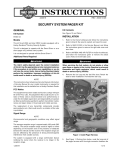
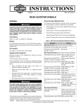
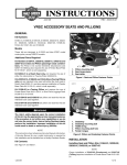
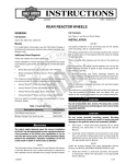
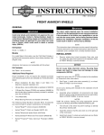
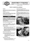
-J00876
REV. 2009-03-09
SECURITY SYSTEM SMART SIREN KIT
GENERAL
INSTALLATION
Kit Number
2002-2006 VRSCA, VRSCB, VRSCD Models
68328-02
1.
Open the seat.
Models
2.
See Figure 1. Remove the splash guard (mud flap) nuts.
For model fitment information, see the P&A Retail Catalog or
the Parts and Accessories section of www.harley-davidson.com
(English only).
3.
See Figure 2. Lower the mud flap from the installed position and allow it to rest on the rear tire.
is01303
Kit Contents
See Figure 21 and Table 1.
Additional Parts Required
The rider's safety depends upon the correct installation
of this kit. Use the appropriate service manual procedures.
If the procedure is not within your capabilities or you do
not have the correct tools, have a Harley-Davidson dealer
perform the installation. Improper installation of this kit
could result in death or serious injury. (00333a)
NOTE
Some models reference service manual information. A service
manual for your model motorcycle may be required for this
installation and is available from a Harley-Davidson Dealer.
REMOVAL
1.
Figure 1. Remove Mud Flap Nuts (2002-2006 VRSCA/B/D
Models)
is01304
Refer to the owner's manual and follow the instructions to
disarm the security system.
To prevent accidental vehicle start-up, which could cause
death or serious injury, disconnect negative (-) battery
cable before proceeding. (00048a)
To prevent accidental vehicle start-up, which could cause
death or serious injury, remove main fuse before proceeding. (00251b)
2.
For All Models except 2002-2003 Touring and 2003Later Softail: Refer to the owner's manual and follow the
instructions to disconnect the battery, negative (-) cable
first or remove the main fuse.
Figure 2. Lower the Mud Flap (2002-2006 VRSCA/B/D
Models)
For 2002-2003 Touring and 2003-Later Softail Models:
Remove seat following the instructions in the service
manual and disconnect the battery, negative (-) cable first.
Save seat hardware for installation.
-J00876
1 of 9
When servicing the fuel system, do not smoke or allow
open flame or sparks in the vicinity. Gasoline is extremely
flammable and highly explosive, which could result in
death or serious injury. (00330a)
4.
6.
See Figure 4. Route the siren harness lead out from under
the right side of the fender. Obtain the siren (1) from the
kit and insert connector [142B] (2) into the siren receptacle
until the connector latches securely.
7.
See Figure 5. With the sounder disc facing the mud flap,
position the siren on the mud flap. Secure the siren (1) to
the existing hook fasteners (3) on the mud flap with the
plain-backed loop fastener (2) from the kit.
Remove the fuel cap and the fuel filler boot. Save the boot
for installation. Install the fuel cap.
is01307
is01305
3
1
1
2
1. Fuel pump and sender connector
2. Security siren connector [142B] under here
3. Two-wire connector [95B]
2
Figure 3. Locate Connector [142B] (All 2002-2006 VRSC
Models) (Shown with Fuel Cap and Filler Boot Removed)
NOTE
See Figure 3. The security siren connector is a three-wire
connector, not to be confused with the two-wire connector (3)
tied to the harness (except on California models).
5.
See Figure 3. Locate the security siren connector (2), at
the end of the harness lead that wraps around the top of
the fuel tank.
3
1. Siren
2. Plain-backed loop fastener (from kit)
3. Hook fastener (2, on vehicle)
Figure 5. Secure Siren Box (2002-2006 VRSCA/B/D Models)
8.
Disconnect the fuel pump and sender connector (1) to free
the security siren connector. The protective cap and wire
tie on the security siren connector can be discarded.
Install the mud flap to the underside of the fender. Install
and tighten the mud flap nuts to 8-12 Nm (70.8-106.2 inlbs). Remove the fuel cap. Install the fuel filler boot. Install
the fuel cap.
is01306
When closing the seat, make sure the ignition switch is in
the FUEL position. If the ignition switch is in any other
position when the seat is closed, the seat latch mechanism
could be damaged. (00196a)
2
9.
1
3
Refer to the owner's manual and follow the instructions to
close the seat.
10. Install the main fuse per the instructions in the owner's
manual.
2006-2007 VRSCR Models
1.
1. Siren
2. Connector [142B]
3. Sounder disc
Figure 4. Install Siren Connector (All 2002-2006 VRSC
Models)
-J00876
Open the seat.
When servicing the fuel system, do not smoke or allow
open flame or sparks in the vicinity. Gasoline is extremely
flammable and highly explosive, which could result in
death or serious injury. (00330a)
2.
Remove the fuel cap and the fuel filler boot. Install the fuel
cap.
2 of 9
NOTE
The security siren connector is a three-wire connector, not to
be confused with the two-wire connector (3) tied to the harness
(except on California models).
6.
See Figure 4. Route the siren harness lead out from under
the right side of the fender. Obtain the siren (1) from the
kit and insert connector [142B] (2) into the siren receptacle
until the connector latches securely.
3.
7.
See Figure 8. With the sounder disc (2) facing out, clip
the siren (1) onto the mud flap (3) as shown.
8.
Install the rear outer fender by sliding the tabs on the front
of the fender into the slots on the inner fender locking tabs.
See Figure 3. Locate the security siren connector (2), at
the end of the harness lead that wraps around the top of
the fuel tank.
Disconnect the fuel pump and sender connector (1) to free
the security siren connector. The protective cap and cable
strap on the security siren connector can be discarded.
4.
See Figure 6. Remove the flanged hex nut (2) and flat
washer (3) that retain the passenger seat (1) and remove
the seat.
is01308
2
NOTE
Verify that the outer fender tabs are latched with the inner
fender locking tabs.
9.
Press down gently on the outer fender to seat the fender
against the frame.
is01310
2
3
1
1
3
1. Passenger seat
2. Flanged hex nut
3. Flat washer
Figure 6. Remove Passenger Seat (2006-2007 VRSCR
Models)
1. Siren
2. Sounder disc
3. Mud flap
Figure 8. Secure Siren Box (2006-2007 VRSCR Models)
is01309
2
10. Install the four screws and flat washers that retain the rear
outer fender and tighten to 4.5-7.5 Nm (40-66 in-lbs).
1
11. Install the passenger seat with the flanged hex nut and
flat washer removed earlier. Tighten to 20-25 Nm (15-19
ft-lbs).
3
1. Rear outer fender
2. Hex head screw (4)
3. Spacer washer (4)
12. Install the mud flap to the underside of the fender. Install
and tighten the mud flap nuts to 8-12 Nm (70.8-106.2 inlbs). Remove the fuel cap. Install the fuel filler boot. Install
the fuel cap.
When closing the seat, make sure the ignition switch is in
the FUEL position. If the ignition switch is in any other
position when the seat is closed, the seat latch mechanism
could be damaged. (00196a)
Figure 7. Fender Mounting Fasteners (2006-2007 VRSCR
Models)
5.
See Figure 7. Remove the four hex head screws (2) and
spacer washers (3) that retain the rear outer fender (1).
Remove the fender by sliding back and lifting up.
-J00876
After installing seat, pull upward on seat to be sure it is
locked in position. While riding, a loose seat can shift
causing loss of control, which could result in death or
serious injury. (00070b)
3 of 9
13. Refer to the owner's manual and follow the instructions
given to close the seat.
9.
14. Install the main fuse per the instructions in the owner's
manual.
2002-2007 FL Touring Models
1.
Remove the right side saddlebag per the instructions in
the owner's manual. Gently pull the side cover from the
frame downtubes.
2.
See Figure 10. Remove the two flange nuts (2) from the
electrical bracket (1). Pull the bracket assembly, with the
electronic control module (ECM) and connector attached,
away from the side of the battery box.
2007 and Later VRSCA, VRSCD, VRSCF Models
1.
Open the seat.
2.
Remove the passenger seat (pillion) mounting nut and
washer at the left front of the seat. Remove the rider seat
retaining post at the right front.
3.
Slide the passenger seat forward slightly to detach it from
the mounting tab on the fender then slide it back and out
from under the grab strap. Lift the seat away from the
motorcycle.
is01311
is05233
1
2
Install the main fuse per the instructions in the owner's
manual.
4
1
3
3
2
4
1.
2.
3.
4.
Figure 9. Secure Siren Box (2007 and Later VRSCA,
VRSCD, VRSCF Models)
4.
5.
1.
2.
3.
4.
Main harness lead
Security siren connector [142B]
Siren
Sounder disc
See Figure 9. Locate the three-wire security siren connector [142B] (2), tied back to the harness lead (1) that
travels alongside the TSSM mounting caddy. Cut the tape
to free the connector and wires.
Insert the siren (3) connector [142B] into the siren receptacle until the connector latches securely.
6.
With the sounder disc (4) facing out, clip the siren onto
the TSSM mounting caddy as shown.
7.
Slide the passenger seat under the grab strap, and engage
the mounting tab on the fender into the slot in the underside of the seat. Make sure harnesses are not pinched
under the passenger seat frame.
Electrical bracket
Flange nuts (2)
Electronic control module (ECM)
ECM connector
Figure 10. Electrical Bracket (2002-2007 FL Touring Models)
3.
Refer to Figure 11. Remove the siren harness lead (1)
from the back of the electrical bracket and take the protective cap (2) off of the security siren connector [142B].
4.
See Figure 12. Insert the security siren (1) connector
[142B] into the siren box receptacle until the connector
latches securely.
5.
Refer to Figure 13. Slide the siren (2) into place on the
back of the electrical bracket (1) so the sounder disc faces
out.
NOTE
Be sure that the cables and conduit are properly routed so they
are not pinched during assembly.
6.
See Figure 14. Install the electrical bracket assembly with
the siren back onto the studs on the side of the battery
box. Install the two flange nuts onto the studs, and tighten
to 4.1-5.4 Nm (36-48 in-lbs).
After installing seat, pull upward on seat to be sure it is
locked in position. While riding, a loose seat can shift
causing loss of control, which could result in death or
serious injury. (00070b)
8.
Install the passenger seat with the rider seat retaining post
at the right front, and the seat mounting nut and washer
at the left front.
Tighten the nuts to 11-17 Nm (97-150 in-lbs).
-J00876
4 of 9
is01312
is01314
1
2
2
1
1. Electrical bracket
2. Siren
Figure 13. Slide Siren into Place (2002-2007 FL Touring)
1. Siren harness lead
2. Protective cap
is01315
Figure 11. Siren Wire Harness (2002-2007 FL Touring)
2
is01313
3
1
1
2
1. Siren
2. Electrical bracket
3. Sounder disc
1. Security siren
2. Siren connector [142B]
Figure 14. Siren and Electrical Bracket Installed (2002-2007
FL Touring Models)
Figure 12. Insert Siren Connector (2002-2007 FL Touring)
2008 and later FL Touring Models
7.
Align the barbed studs on the side cover with the grommets in the frame, and push side cover firmly into place.
1.
Follow the instructions in the owner's manual to remove
the left side saddlebag, gently pull the side cover from the
frame downtubes.
8.
Install the right side saddlebag per the instructions in the
owner's manual.
2.
See Figure 15. Remove the security siren connector [142B]
(3) from the retainer on the electrical caddy.
Insert security siren (4) connector [142B] into the security
siren receptacle (5) until the connector latches securely.
After installing seat, pull upward on seat to be sure it is
locked in position. While riding, a loose seat can shift
causing loss of control, which could result in death or
serious injury. (00070b)
9.
For 2002-2003 Models: Refer to the owner's manual and
follow the instructions given to connect the battery cables.
Install the seat.
10. For 2004-2007 Models: Refer to the owner's manual and
follow the instructions given to install the main fuse or
connect the battery cables.
-J00876
5 of 9
is04979
is01316
6
4
2
1
5
3
1.
2.
3.
4.
5.
6.
Left-side electrical caddy
Main fuse
Security siren connector [142B]
Security siren
Security siren receptacle
Sounder disc
2
1
3
1. Siren mounting area
2. Siren connector [142B]
3. Harness clip
Figure 15. Siren Installation (2008 and Later FL Touring
Models)
3.
Slide the siren into place on the left side of the electrical
caddy so the sounder disc (6) faces out.
4.
Refer to the owner's manual and follow the instructions to
install the main fuse.
5.
Align the barbed studs on the side cover with the grommets in the frame and push side cover firmly into place.
6.
Install the left side saddlebag per the instructions in the
owner's manual.
2003 and later Softail Models EXCEPT FXCW/C
1.
3.
See Figure 16. Remove the siren connector [142B] (2)
from the receptacle in the siren mounting area (1) of the
electrical panel.
4.
See Figure 17. Insert security siren (1) connector [142B]
into the siren box receptacle until the connector latches
securely.
5.
Orient the siren (1) as shown, with the harness connector
(2) toward the bottom and the sounder disc (5) facing out.
Carefully snap the siren into the electrical panel.
6.
Insert the siren harness lead (4) into the harness clip (3)
to keep the harness clear of other components.
7.
If necessary, secure the connector wiring to the electrical
panel wiring with a cable strap (not provided).
8.
Hook the slot at the top of the splash guard over the tab
on the rear fork and install the guard with the two screws
removed earlier. Tighten securely.
9.
Install the right side saddlebag (if equipped) per the
instructions in the owner's manual.
Remove the right side saddlebag (if equipped) per the
instructions in the owner's manual.
NOTE
The siren connector is installed on an electrical panel under
the rear fender on all Softail models. The rear of the motorcycle
may have to be raised slightly to allow removal of the splash
guard.
2.
Figure 16. Siren Connector (Softail Models EXCEPT
FXCW/C) (Rear Fender View with Rear Wheel Removed)
Remove the two bolts at the bottom of the splash guard.
Bend the upper right corner of the splash guard toward
the rear tire and lift upward to unhook the splash guard
from the tab on the rear fork. Remove the guard from
beneath the fender.
10. Refer to the owner's manual and follow the instructions
given to connect the battery cables or install the main fuse.
After installing seat, pull upward on seat to be sure it is
locked in position. While riding, a loose seat can shift
causing loss of control, which could result in death or
serious injury. (00070b)
11. Install the seat.
-J00876
6 of 9
is01317
is05260
3
1
2
4
5
1
3
2
1.
2.
3.
4.
5.
4
Security siren
Siren connector [142B]
Siren harness clip
Siren harness lead
Sounder disc
1.
2.
3.
4.
Figure 17. Siren Mounting (Softail Models EXCEPT
FXCW/C)
2008 and later FXCW/C (Rocker) Models
Figure 18. Electrical Panel (FXCW/C Models)
3.
Remove the siren connector [142B] from the receptacle
(3) near the top of the electrical panel (2).
4.
Insert siren box connector [142B] into the siren box
receptacle until the connector latches securely.
5.
See Figure 19. Position the siren box (1) with the harness
connector toward the rear and the sounder disc (2) facing
out. Carefully snap the siren box into the pocket (3) on the
right side of the electrical panel.
6.
Install the electrical compartment cover. Tighten the
screws with washers to 4.1-6.8 Nm (36-60 in-lbs).
NOTE
Note the fender wire routing and hardware locations before
removal.
1.
2.
Remove the rear fender from the vehicle. Refer the service
manual and follow the instructions to:
a.
Disconnect the rear wiring harness connector [7]
halves.
b.
Remove the lower fender mounting bolts and
washers.
c.
Remove the upper fender mounting screws and
washers.
d.
Remove the fender.
Harness clipped to cover
Electrical panel
Siren connector [142B] receptacle
Rear fork (swing arm)
is05261
See Figure 18. Remove the harness (1) clipped to the
right side of the electrical compartment cover (splash
guard, already removed in photo) just forward of the rear
wheel. Remove the two hex socket head screws and
washers fastening the cover and remove the cover from
the vehicle.
4
2
1
1.
2.
3.
4.
3
Siren box
Sounder disc
Pocket on right side of electrical panel
Rear fork (swing arm)
Figure 19. Siren Mounting (FXCW/C Models)
-J00876
7 of 9
7.
8.
Install the rear fender to the vehicle. Refer to the service
manual and follow the instructions to:
a.
Place the fender into position.
b.
Loosely install the fender mounting hardware.
c.
Tighten the fender mounting hardware, in the indicated sequence, to the specified torque.
d.
Connect the rear wiring harness connector [7] halves.
7
is01318
6
4
3
Refer to the owner's manual or service manual, and follow
the instructions given to connect the battery cables or
install the main fuse.
1
5
After installing seat, pull upward on seat to be sure it is
locked in position. While riding, a loose seat can shift
causing loss of control, which could result in death or
serious injury. (00070b)
9.
2
Install the seat.
1.
2.
3.
4.
5.
6.
7.
2004 and later Dyna Models
1.
See Figure 20. Firmly grasp both sides of the electrical
caddy cover (1) and pull to remove.
NOTE
When pulling the electrical caddy away from the motorcycle,
make sure that the wiring connections are not disturbed. Pull
the caddy away just far enough to allow installing the siren.
2.
Cover
Front fastener
Electrical caddy
Ignition module
Siren
Sounder disc
Top fasteners (2)
Figure 20. Install Siren in Electrical Caddy (Dyna Models)
Remove the front electrical caddy screw and washer (2).
Remove the two top electrical caddy screws and washers
(7).
ALL Models
3.
Tip the top of the electrical caddy (3) away from the vehicle
slightly. Turn the siren (5) so the sounder disc (6) faces
upward and the wire receptacle is facing the motorcycle
as shown.
4.
Remove the siren harness lead from behind the electrical
caddy, and take the black dust cap off of the security siren
connector [142B].
The siren may not function properly when first installed. NiMH
(Nickel Metal Hydride) rechargeable batteries discharge fairly
rapidly when stored. They will lose as much as 1% - 2% of
their charge per day, and after a few months of storage at room
temperature will be mostly discharged. If stored for a very long
period without charging, they may need a few charging cycles
to regain their full capacity.
5.
Insert connector [142B] into the siren receptacle until the
connector latches securely. Insert the siren into the back
of the caddy, beneath the ignition control module (4).
NOTE
To charge the NiMH battery, operate your motorcycle for a
minimum of 4 hours.
SIREN DIAGNOSTICS
6.
Install but do not tighten the front electrical caddy screw
and washer (2). Install the top electrical caddy screws and
washers (7). Tighten the top screws to 11.3 Nm (100 inlbs). Tighten the front screw to 5.6 Nm (50 in-lbs).
•
If the siren is armed and the internal siren battery is discharged, shorted, disconnected or has been charging for
a period longer than 24 hours, the siren will respond with
three chirps on arming instead of two.
7.
Refer to the owner's manual and follow the instructions
given to install the main fuse.
•
The internal siren battery may not charge if the vehicle's
charging system is producing less than 12.5 volts.
8.
Install the electrical caddy cover.
•
If the siren does not chirp two or three times on a valid
arming command from the security system, the siren is
either not connected, not working or the siren wiring was
opened or shorted while the siren was disarmed.
•
If the siren enters the self-driven mode where it is powered
from the siren's internal 9-volt battery, the turn signal lamps
may or may not alternately flash. If the security system
activates the siren, the turn signal lamps will alternately
flash. If the siren has been armed and a security event
occurs, and the siren is in self-driven mode, the siren will
alarm for 20 to 30 seconds and then turn off for 5 to 10
-J00876
8 of 9
seconds. This alarm cycle will be repeated ten times if the
siren is in the self-driven mode.
SMART SIREN BATTERY REPLACEMENT
SERVICE PARTS
is01319
The siren's internal 9-volt battery is rechargeable and does not
need to be replaced on a regular basis. Battery life under
normal conditions is approximately three to six years.
NOTES
When battery replacement is needed, only a nickel metal
hydride (NiMH) 9-volt battery should be used in the siren.
Use Security System Siren Battery Replacement Kit (6901800). In addition to the 9-volt NiMH battery, this kit contains a
replacement battery cover, cover gasket and instructions
needed to provide continued proper operation of the siren.
2
To Replace the Smart Siren Battery:
1
1.
Refer to the owner's manual and follow the instructions
given to disarm the security system.
2.
Remove the siren box from the vehicle. Reference the
siren installation procedures for your model in this
Instruction Sheet.
Figure 21. Service Parts: Smart Siren
3.
Follow the instructions included with the Battery Replacement Kit to remove the battery cover and remove and
replace the battery. Replace the old seal and battery cover
with the new items from the kit.
Table 1. Service Parts
4.
Install the siren box into the vehicle.
5.
Dispose of the old NiMH battery in accordance with local
regulations.
-J00876
Item
Description (Quantity)
Part Number
1
Smart Siren, security system
68958-07B
2
Loop fastener, plain-backed,
59274-01
210 mm x 38 mm
(8-1/4 in x 1-1/2 in) - Used for
2002-2006 VRSCA/B/D Models
Only
9 of 9