1
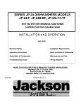
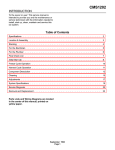
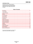
CONSERVER II
CHEMICAL SANTIZING
DISHWASHER
SERVICE MANUAL
INCLUDES:
-Warranty Policy
-Specifications
-Installation Requirements
-Maintenance and Care
-Operating Instructions
-Illustrated Parts List
-Description of Components
-Electrical Diagrams
WORLD HEADQUARTERS & MANUFACTURING OPERATIONS
Highway 25E, P.O. Box 1060
Barbourville, KY 40906
888/800-JMSC
FAX 606/532-9196
April 4,1997
7610-100-24-00 Rev A
MANUFACTURERS WARRANTY
ONE YEAR LIMITED PARTS & LABOR WARRANTY
ALL NEW JACKSON DISHWASHERS ARE WARRANTED TO THE ORIGINAL PURCHASER TO BE FREE FROM DEFECTS IN MATERIAL OR
WORKMANSHIP, UNDER NORMAL USE AND OPERATION FOR A PERIOD OF (1) ONE YEAR FROM THE DATE OF PURCHASE, BUT IN NO EVENT
TO EXCEED (18) EIGHTEEN MONTHS FROM THE DATE OF SHIPMENT FROM THE FACTORY.
Jackson MSC agrees under this warranty to repair or replace , at its discretion, any original part which fails under normal use due to faulty material or
workmanship during the warranty period, providing the equipment has been unaltered, and has been properly installed, maintained and operated in
accordance with the applicable factory instruction manual furnished with the machine and the failure is reported to the authorized service agency within the
warranty period. This includes the use of factory specified genuine replacement parts, purchased directly from a Jackson authorized parts distributor or
service agency. Use of generic replacement parts may create a hazard and void warranty certification.
The labor to repair or replace such failed part will be paid by Jackson MSC, within the continental United States, Hawaii and Canada, during the warranty
period provided a Jackson MSC authorized service agency, or those having prior authorization from the factory, performs the service. Any repair work by
persons other than a Jackson MSC authorized service agency is the sole responsibility of the customer. Labor coverage is limited to regular hourly rates,
overtime premiums and emergency service charges will not be paid by Jackson MSC.
Accessory components not installed by the factory carry a (1) one year parts warranty only. Accessory components such as table limit switches, pressure
regulators, pre rinse units, etc. that are shipped with the unit and installed at the site are included. Labor to repair or replace these components is not covered
by Jackson MSC.
This warranty is void if failure is a direct result from shipping, handling, fire, water, accident, misuse, acts of god, attempted repair by unauthorized persons,
improper installation, if serial number has been removed or altered, or if unit is used for purpose other than it was originally intended.
TRAVEL LIMITATIONS
Jackson MSC limits warranty travel time to (2) two hours and mileage to (100) one hundred miles. Jackson MSC will not pay for travel time and mileage that
exceeds this, or any fees such as those for air or boat travel without prior authorization.
WARRANTY REGISTRATION CARD
The warranty registration card supplied with the machine must be returned to Jackson MSC within 30 days to validate the warranty.
REPLACEMENT PARTS WARRANTY
Jackson replacement parts are warranted for a period of 90 days from the date of installation or 180 days from the date of shipment from the factory, which
ever occurs first.
PRODUCT CHANGES AND UPDATES
Jackson MSC reserves the right to make changes in design and specification of any equipment as engineering or necessity requires.
THIS IS THE ENTIRE AND ONLY WARRANTY OF JACKSON MSC. JACKSON'S LIABILITY ON ANY CLAIM OF ANY KIND, INCLUDING NEGLIGENCE,
WITH RESPECT TO THE GOODS OR SERVICES COVERED HEREUNDER, SHALL IN NO CASE EXCEED THE PRICE OF THE GOODS OR SERVICES
OR PART THEREOF WHICH GIVES RISE TO THE CLAIM.
THERE ARE NO WARRANTIES, EXPRESSED OR IMPLIED, INCLUDING FOR FITNESS OR MERCHANTABILITY, THAT ARE NOT SET FORTH
HEREIN, OR THAT EXTEND BEYOND THE DURATION HEREOF. UNDER NO CIRCUMSTANCES WILL JACKSON MSC BE LIABLE FOR ANY LOSS OR
DAMAGE, DIRECT OR CONSEQUENTIAL, OR FOR THE DAMAGES IN THE NATURE OF PENALTIES, ARISING OUT OF THE USE OR INABILITY TO
USE ANY OF ITS PRODUCTS.
ITEMS NOT COVERED
This warranty does not cover adjustments to timer cams or thermostats, cleaning wash arms or strainers, or replacement of wear items such as curtains,
squeeze tubes, drain balls, door guides, or gaskets beyond 30 days from installation of unit. Also not covered are conditions caused by the use of incorrect
(non commercial) grade detergents, excessive supply water temperature or pressure, or hard water conditions.
INDEX
WARRANTY
SPECIFICATIONS
GENERAL INSTRUCTIONS (Installation)
GENERAL INSTRUCTIONS (Operation)
GENERAL INSTRUCTIONS (Preventive Maintenance)
WASH/RINSE HEAD ASSEMBLY
TIMER ADJUSTMENTS
TIMER ASSEMBLY, SPANNER WRENCH TIMERMICRO SWlTCH, SIDE
VIEW of CAM
FUNCTION of SWITCHES, CIRCUIT BREAKER,INDICATOR LIGHTS and
CYCLE COUNTER
REPLACEMENT of SWITCHES in CONTROL PANEL
PERISTALTIC PUMP SANITIZING DISPENSING SYSTEM
SANITIZING AGENT INJECTOR
WASH/RINSE PUMPASSEMBLY
REPLACING SEAL and CERAMIC on WASH/RINSE PUMP
DRAIN VALVEASSEMBLY,STRAIGHTTHROUGH MODEL
SERVICE INSTRUCTIONS (Incoming Water Solenoid Valve)
INSTRUCTIONS for ADJUSTING TENSION of CANTILEVER
APPLYING NYLATRON STRIP to CONSERVER DOOR
TROUBLE SHOOTING GUIDE
INSIDE FRONT COVER
3
4
6
8
9
10
11
12
13
14
15
16
17
18
19
20
22
23
PICTORIALS
BACKS1DEVIEW
RIGHTSIDEVIEW
LEFTSIDEV1EW
INCOMING PLUMBING, VACUUM BREAKER, MERCURY RELAY
ANTI-FOAM VALVE
ELECTRICAL DRAWINGS
PARTSUST
NOTES
PARTS DISTRIBUTORS
25
26
27
28
29
30,31
32,33
34
INSIDE BACK COVER
SPECIFICATIONS
Operating Capacity
Thermometers
Phase
Approximate
Racks per hour
(NSF Rated) Dishes per hour
74
1900
Wash - °F
Water Requirements (NSF Rated)
140
1 (3 wire)
Dimensions
Glasses per hour
1900
Inlet Temperature - °F
140
Depth
25"
90
4.0
Gal per hour
188
Flow Pressure PSI
20
Flow GPM
16.5
Inlet IPS
3/ 4"
Drain IPS
2"
Available Chlorine during rinse cycle Min. 50 ppm
Width
Height
Standard Table Height
Maximum Clearance for
Dishes
44"
67 1/4"
34"
15"
Operating Cycle
Total Cycle - Sec
Wash Tank Capacity
Gallons
Racks
Wash Pump Capacity (2 pumps)
Gal Per Min
55
Dish, 19 3/4 x 19 3/4
Combination
Electrical Rating
Volts
Shipping Weight
CONSERVER
115
Approx Basic Model
Wash Pump Motor
Horsepower (2)
Total Load Amps
26
Optional
Optional
1
All dimensions and specifications are subject to change without notice.
3
350 lbs.
GENERAL INSTRUCTIONS
(INSTALLATION)
Note: Read the following instructions carefully. Proper installation of your Conserver Dishwasher
will ensure proper machine operation.
1. Cut straps holding machine to base of crate, ease machine on to floor and move into place of
installation.
2. Connect drain line to bottom of machine (2 IPS female fitting on front of machine) to conform with local
and/or national codes. Drain is a gravity feed system from the machine.
a. The Conserver is designed to accommodate an external scrap trap if one is shipped with the unit. The
scrap trap should be placed beneath the unit with the top opening to the right of the pump and motor
mounting shelf so that the top hole of the scrap trap is in line with the drain opening from the machine.
b. Direct the drain line from the dishwasher to the top of the trap and plumb accordingly with 2" pipe of the
necessary length. Connect a 2" fitting to the back of the scrap trap and plumb to the drain line. The
drain line is a gravity feed system from the dishwasher to the scrap trap and also from the scrap trap to
the drain line. Scrap trap aids sluggish drains by containing machine water as it drains and letting it
drain off slower.
3. Connect incoming 33/4" water line with capacity to supply 16.5 gallons per minute with a flow rate of 20
PSI at a temperature of 140°F. This connection is just before the Y-strainer. Connect to conform with local
and/or national codes (standards).
a. It is recommended that in areas where there is fluctuating water pressure a restrictor valve allowing 8
gallons of water per minute be installed. This will help to provide a steady fill rate. The restrictor should
be located down the line from the Y-strainer.
4. Install the proper circuit breaker, wire and conduit size to conform with local and/or national codes.
Refer to data plate for electrical codes.
5- The electrical connections are made to the terminal block located in the dispenser/control box on the
top of the machine. The terminal block is located on the back wall of the box with a grounding lug next
to it. Three wires L1, N, and a ground wire should be passed through the hole in the back of the box
and connected to the terminal block as marked.
6. Do not apply power until step #9.
7. Turn on water supply to machine; check for any leaks in plumbing and connections.
8. Place the open end of the red tube into a container of detergent; white, into a container of sanitizer;
and blue, into a container of rinse additive.
9. To energize electrically, proceed as follows:
a. Turn on customer's circuit breaker controlling the machine.
b. Check voltage at incoming terminals L1 and N. It should match data plate voltage. Voltage at L1
should be checked to ground to ensure that a high (or wild) leg is NOT connected. (Voltage
exceeding 150V to ground would indicate a high leg.)
c. If voltages are in required range, turn on circuit breaker on the side of the dispenser/control box.
10. To fill the unit with water:
a. Located on the right side of the control box is a two-positioned momentary switch. To fill this unit
initially with water, push and hold the switch to the top of the unit until the water reaches the-top of
the cut out for the drain opening. Release the switch and it will return to the off position.
b. After the unit is full of water, check for leaks and see if the solenoid valve opens and closes as the
fill switch is turned on and off.
c- After checking the plumbing lines for leaks, run the unit through a complete cycle to determine the
proper water level. The proper level for the water is the top of the cut out for the drain opening
leading from the machine into the drain strainer and stopper. If this level is either not reached or is
exceeded, please turn to the timer section of this manual to determine the proper adjustment of the
timer that has to be made.
d. Above each peristaltic pump is a priming switch. After making sure that the feeder tubes to the
pumps are in their proper containers, as marked on the pumps, press the switch and hold it until
there is a discharge of the fluid into the machine. This is to be done to each pump before the initial
operation of the machine. Water must be in wash-rinse tub to prevent discoloration or deterioration
of the stainless tub by chemicals.
e. The dishwasher is now ready to proceed with the washing of dishes in accordance with operating
instructions in this manual.
ITEM
P/N
DESCRIPTION
0046500
DRAIN OUTLET (2" GRAVITY FEED)
INCOMING WATER CONNECTION (3/4"
IN BACK)
CUSTOMER ELECTRICAL SERVICE
CONNECTION (IN BACK)
DETERGENT DISPENSER PUMP
115V, 60 CYCLE
DETERGENT DISPENSER PUMP
230V, 50 CYCLE
RINSE ADDITIVE DISPENSER PUMP
115V, 60 CYCLE
1.
2.
3.
4.
0046000
5.
0046500
0046000
6.
0046500
0046000
7.
8.
9.
10.
11.
12.
5
0154300
0154300
0034000
0012000
RINSE ADDITIVE DISPENSER PUMP
230V, 50 CYCLE
SANITIZING SOLUTION
DISPENSER PUMP, 115V, 60 CYCLE
SANITIZING SOLUTION
DISPENSER PUMP, 230V, 50 CYCLE
PRIMING SWITCHES
CONTROL SWITCHES
COUNTER CYCLE
CIRCUIT BREAKER
DISPENSING HOSES
FILL LEVEL 5/16" ABOVE TOP
OF CUTOUT FOR DRAIN
GENERAL INSTRUCTIONS
(OPERATION)
Note:
Read the following instructions carefully. Proper operation of your Conserver Dishwasher
will ensure clean and sanitized glasses and dishes at optimum efficiency.
Dish Preparation:
1.
2.
3.
4.
Scrape dishes thoroughly.
Pre-wash by soaking or spraying with a pre-rinse hose.
Place dishes and cups in dish rack; cups, upside down.
Place glasses and silverware in combination glass silverware rack; glasses, upside down. Scatter
silverware loosely on bottom. Do not put glasses on top of silverware.
Note: Silverware should be washed upright in a special compartment silverware rack for best
results.
These silverware compartment racks are available through your dealer or service agency.
Machine Operation:
1.
2.
3.
4.
5.
6.
7.
8.
9.
Insert drain strainers.
Be sure the drain stoppers are in place.
Insert two racks of dishes and close all doors.
Check the levels of the detergent, rinse additive and sanitizing agent containers. Fill them if necessary.
To put the unit into operation at the beginning of the day or a meal period, make sure the circuit
breaker on the right side of the dispenser/control box on top of the machine is on.
For the initial fill, push the fill switch on the right side of the dispenser/control box. Hold the switch in
this position until the water level reaches 5/16" above the top of the cut out for the drain opening.
When the unit is full of water press the start switch and count to three. This activates the time cycle
and the cycle light will come on.
When the light goes out, open the side doors and slide out the racks of clean dishes. Slide in two
racks of soiled dishes and repeat steps #7 and #8.
At the end of the mealtime, shut off the circuit breaker on the dispenser/control box and drain the unit
by pulling on the drain stoppers. Clean any food debris out of the basket strainers.
Note: If the unit is not operated for extended periods of time, the water will drain out or go
down in level. Be sure to check the water level before operating and if the level is down, see
step #6
6
ITEM
P/N
DESCRIPTION
ITEM
1.
2.
0152100
0169000
PUMP INTAKE STRAINERS (2)
WASH-RINSE WATER THERMOMETER
7.
3.
4.
5.
0053813
0008600
0171100
0173200
0054106
DRAIN LINE STOPPERS (2)
CANTILEVER ARM
TIMER, 115V, 60 CYCLE
TIMER, 220V, 50 CYCLE
DRAIN SOLENOID "T" STYLE, 115V
6.
P/N
8.
9.
0009000
0087000
10.
11.
0001210
0001211
12.
0001203
7
DESCRIPTION
FILL LEVEL 5/16" ABOVE TOP OF
CUTOUT FOR DRAIN
CANTILEVER DOOR SPRING
PUMP & MOTOR ASSEMBLY,
60 CYCLE
OPERATIONS DECAL
TIMER DECAL AND DET, SAN,
RIN DECALS
CLEAN STRAINER DECAL
GENERAL INSTRUCTIONS
(PREVENTIVE MAINTENANCE)
THE FOLLOWING IS TO BE PERFORMED AS NEEDED.
Note:
Read the following instructions carefully. Proper maintenance of your Conserver
Dishwasher will ensure optimum service with a minimum of down time.
Before removing the cover to the Dispenser/Control Box turn off the circuit breaker on the
side of the box.
1. Remove all lime and corrosion deposits. (Weekly or as needed.)
a. Remove all three hoses for the pumps from their containers. b. Remove the three hoses from the sump on
the front of the machine and place them off to
the side in another container- This will prevent the chemicals from entering the sump
during the cycling of the machine.
c. Fill machine with wash water as would ordinarily be done for washing. d- Open door and place two cups or
less of deliming compound into water. (Be sure to follow
the amount and directions given on the package or bottle of the compound used.) The
compound is available from your detergent supplier.
e. Close door and push start switch. Run through four cycles.
f. When cycle light goes out, open door and examine the interior. All lime should be removed
and parts should be shiny. If not, scrub stubborn deposits with brush and repeat operation.
(Protect hands with waterproof gloves.)
g. After the interior is clean, turn off circuit breaker, empty wash water by removing the drain
stoppers. Remove basket strainers and flush away all debris and build-up.
h. Replace the basket strainers. Turn circuit breaker on to refill the machine and allow it to
run through a cycle, then again drain as instructed in (f).
i. Return the three hoses to the sump and install in the hose bracket.
j. Return the three hoses to their proper containers and prime the pumps.
2. Clean the strainer baskets to provide for the maximum amount of water return to the pumps
possible. (Daily or as needed.)
a. Remove baskets from drain openings and brush away any debris or force it out of the strainer
openings with water.
3. Clean Y-strainer on incoming water line. (Yearly or as needed.)
a. Water to machine must be turned off for this operation.
b. Remove plug and clean strainers (as water is trapped near strainer and 120° - 140°F, use care in
removing plug and have container to catch water.
4. Clean Wash/Rinse tubes (Weekly or as needed.) (See drawing next page.)
a. Turn the circuit breaker to off position.
b. Open door and drain machine by lifting drain stoppers.
c. When empty, replace drain stoppers.
d. Loosen the two thumb screws opposite each other on each the top and bottom
assemblies.
e. Pull the assemblies out of the bases.
f. Remove the hub assembly by loosening the nut with a wrench.
g. After hub is off, remove the end plugs and either flush with clean water or a brush.
(A straightened paper clip makes an excellent tool for cleaning the nozzles.)
h. Clean the hub by either soaking or brushing with a deliming solution. (A toothbrush makes
an excellent tool.)
i. The bearings cannot be replaced separately; the whole hub must be replaced if it is needed.
j. Reassemble the Wash/Rinse assembly by reversing steps d, e, f, and g.
5. Clean any deposits which may have built up on exterior moving parts. (Only as needed.)
a. Remove with clean cloth. (A stainless polish or oil may be used to loosen deposits.)
b. Deposits around fill switch can be removed with a dry toothbrush.
6. If an external scrap trap is supplied with the unit, flush the drain line and the scrap trap. (Weekly or as
needed.)
a. Remove the 2" pipe nipple on the end of the fitting underneath the drain outlet.
b. Insert a hose into the line and flush the line out with a steady stream of water.
c. Remove the scrap tray from the scrap trap and empty the food debris into a disposable container.
d. Before reinstalling the scrap tray, flush the line from the machine to the trap, then from
the trap to the drain line.
e. Reinstall the scrap tray and replace the lid.
7. Never allow the main pump to be operated without water in the machine.
8. Inspect the peristaltic pumps on a weekly schedule for cracks in the tubes. On the right side of the
dispenser/control box there is a counter to register each time the unit completes a full cycle. Anticipate
about every 30,000 cycles having to replace the tubes in the peristaltic pumps. The tubes and
instructions are available from your area parts distributor listed in the back of this manual.
WASH RINSE HEAD ASSEMBLY
NEW STYLE
P/N 0199400
ITEM P/N
DESCRIPTION
1.
0199401 TUBE AND HUB ASSEMBLY
2.
0199402 BEARING SPINDLE
3.
0199403 RETAINING RING OR CLIP
4.
0199404 BEARINGS (2 EACH)
5.
0199501 END PLUGS
9
WASH RINSE HEAD ASSEMBLY P/N 0199500
4 PER MACHINE
ITEM
P/N
DESCRIPTION
1.
2.
3.
0199501
0199503
END PLUGS (4)
VEE JETS (16)
TUBE (4)
4.
5.
6.
7.
0199504
0199504
0199504
0199504
INTERNAL SHAFT
HEX BUSHING COMPLETE UNIT
BEARINGS 4 EACH
EXTERNAL SHAFT
TIMER ADJUSTMENTS
The timer is a self-contained (frame-mounted) timer of the repeating cycle type. It is mounted in the
control box on the top of the machine to control the automatic functions of the machine. The timer motor
operates on 110 VAC, 60 cycles, taking 90 seconds to complete one full revolution. There are six micro
switches which are controlled by rotating cams driven by the timer motor. Two of the cams are fixed and
cannot be adjusted. The remaining four cams are adjustable and can be adjusted to either lengthen or
shorten the desired operation.
Remove the power to the machine when making all timer adjustments.
Included and taped in each control panel is a spanner wrench (as shown in the drawing). This wrench is
needed to adjust the cams on the timer. The cams are preset at the factory but may have to be
readjusted for different conditions of the country and for the different brands of detergent, rinse additive
and sanitizing solutions. On both sides of the four adjustable cams, there are holes into which the
spanner wrench is placed to apply leverage to make the desired change. The left side of the cam will
always start an operation and the right side will end it. The cam on the right side is the one that will be
adjusted more often since this one determines the length of the operation.
When making adjustments to the timer cams, be sure that the first cam next to the timer motor is in its
stop position in the notch. Place one hand over the timer motor with your thumb lodged next to or on the
first cam so that it will not move when the other cams are being adjusted. To make the adjustment, place
the wrench in the holes on the right side of the cam. If a longer operating time is desired, increase the
gap between the left and right side of the cam. If a shorter operating time is desired, decrease the gap
between the left and right side of the cam. At the extreme end from the timer motor, there is a cam
marked in five-degree increments. Every four degrees equals one second of the timer's revolution.
Function of each micro switch starting from the timer motor and going left to right
Timer Motor Micro Switch: controlled by a fixed cam that controls the total length of the cycle. It is
activated by engaging the fill/start switch in the start position.
Detergent Micro Switch: controlled by an adjustable cam. It operates the peristaltic pump that
dispenses the detergent. By adjusting the right side of the cam, you can either increase or decrease your
amount of detergents.
Drain Solenoid Micro Switch: controlled by a fixed cam. It opens the solenoid valve during the cycle
that drains the wash water out of the unit.
Fresh Water Solenoid Valve Micro Switch: controlled by adjustable cam. It is important that the unit
have two-and-a-half gallons of water in it during the wash and rinse cycles. The proper level indicator is
the height of the cut out leading into the drain strainer and stopper. By adjusting the right side of the cam,
you can either increase or decrease your water supply to meet this required level. Fill water is turned on
before drain cycle ends to ensure machine is flushed before filling.
Rinse Agent Micro Switch: controlled by an adjustable cam. It operates the peristaltic pump that
dispenses the rinse agent. By adjusting the right side of the cam, you can either increase or decrease
your amount of rinse additive. It should activate during the fill cycle.
Sanitizing Agent Micro Switch: controlled by an adjustable cam. It operates the peristaltic pump that
dispenses the sanitizer solution. By adjusting the right side of the cam, you can either increase or
decrease your amount of sanitizer solution. It should activate during the fill cycle. When the timer is
preset at the factory, it is set to dispense 24 milliliters of detergent, 18 milliliters of rinse additive and 16
milliliters (50 parts per million) sanitizing agent based on an 8.4% solution of Sodium Hypochlorite.
10
1.
2.
3.
4.
5.
6.
7.
8.
TIMER MOTOR
TIMER MOTOR CAM (F)
DETERGENT CAM (A)
DRAIN SOLENOID CAM (F)
FRESH WATER SOLENOID CAM (A)
RINSE ADDITIVE AGENT CAM (A)
SANITIZING AGENT CAM (A)
DEGREE CAM (F)
F—FIXED CAM
A—ADJUSTABLE CAM
FUNCTION of SWITCHES,
CIRCUIT BREAKER, INDICATOR
LIGHT and CYCLE COUNTER
Circuit Breaker — The circuit breaker is rated at 15 amps and is utilized as a protection
device for the unit
Fill Switch — The Fill switch is a spring loaded momentary rocker switch and must be held in
the up position until the water has reached the desired level.
Start Switch — The Start switch is a spring loaded momentary rocker switch and must be
held in the up position for a count of three to start the automatic timer. There is a start switch
on both sides of the control box.
Primer Switches — The primer switches are a spring loaded momentary rocker switch
located over each peristaltic dispensing pump. The switches are utilized to operate the pumps
when it is necessary to refill the intake tubes or pumps after they have been emptied. The
pump is activated by pushing up on the switch and holding it for the desired length of time.
Cycle or Machine Light — This light comes on only when the automatic cycle is in progress
and extinguishes when the cycle is complete.
Cycle Counter — The counter totals each single cycle that the unit goes through and is
activated by the rinse additive micro switch on the timer. This counter cannot be reset
Power On Light — This light is lit all the time the circuit breaker is on.
12
REPLACEMENT of SWITCHES
in CONTROL PANEL
There is one two basic type of manually operated switch utilized on the Conserver
dishwasher. It is the rocker switch.
Before working on the machine, it is important that the power be turned off at the customer's
circuit breaker. To prevent the possibility of electrical shock, trip the breaker to the OFF position.
Then turn the machine circuit breaker OFF located on the side of the control box.
The rocker switch is mounted in a rectangular hole held in position by a bracket. This switch is
designed to be released from the inside and pushed outward. The spring sides must be
depressed to release the switch and bracket from the hole. To remove the bracket from the
switch, wedge a screwdriver in between them then lift up and move off.
If the switch is found to be defective, mount a new one into the bracket and insert it into the hole
in the control box. Make sure that the tab on the switch is in the proper notch on the bracket for
easy operation of the switch. Replace the wires from the used switch terminal by terminal on to
the new switch.
Power can now be applied to the dishwasher and run through cycles checking all
operations.
ROCKER SWITCH
ITEM
1.
2.
3.
4.
5.
DESCRIPTION
CONNECTION TERMINALS
BRACKET SPRING SIDES
PANEL PLATE
BRACKET FRONT
ROCKER BUTTON
13
PERISTALTIC PUMP SANITIZING
DISPENSING SYSTEM
The peristaltic pumps are mounted in the Control/Dispenser Box which is attached to the top of the unit.
The pumps receive their electrical signals from two sources.
The first source is the primer switch, which is used to prime the pump when it is first put into operation
and then every time the agent is changed and/or the tubes are clear of any solution.
The second source is the timer, which activates the pumps during the cycle at the proper time to dispense
the correct agent when needed.
If control box is locked and access to prime switches is not available, just run dishwasher through several
cycles to move liquid from storage bottles to pumps.
Checkout of Sanitizing Injector
The pump can be deemed operational if the following items are observed:
1. If the cam roller assembly rotates during each cycle.
2. If the solution is observed passing through the tube.
Note: Both of these operations must be observed to determine if the sanitizing agent is being
dispensed.
If it is determined that the unit is not operating correctly, the following procedures will aid in correcting the
problem:
1. Make certain that the tube is in the bottle of solution.
2- Make certain that there are no cracks in the tubing and particularly in the pump hose.
3. Check ail wire connections on the pump, the timer cam, and the primer switch.
4. Check to see that there is no debris in the tubes.
5. Make sure that the tubing is inserted into the pump hose so that air is not drawn into the system.
14
SANITIZING AGENT INJECTOR
ITEM
P/N
1.
2.
3.
0046501
0046502
0046503
4.
5.
6.
7.
0046504
0046505
0046506
0046507
P/N465 COMPLETE PUMP ASSEMBLY,
ITEM
PUMP MOTOR, 60 CYCLE
8.
PUMP HOUSING
9.
DESCRIPTION
HOUSING MOUNTING BOLTS
(3) 10/32 FILLSTER HEAD
CAM ROLLER ASSEMBLY
CAM ROLLER SET SCREW
PUMP HOSE
HOSE CLAMPS
10.
11.
15
60 CYCLE
P/N
DESCRIPTION
0046508 FACE PLATE
0046509 PLATE MOUNTING
SCREWS (4) 8/32
0046510 INTAKE OR SUCTION
HOSE
0046510 OUTPUT OR
INJECTOR HOSE
GOULDS ASSEMBLY:
ITEM
P/N
1.
0087001
2.
0087002
3.
0087003
4.
0087004
5.
0087005
6.
0087006
7.
0087006
8.
0087008
9.
0087009
10.
0087010
11.
0087911
12.
0087912
DESCRIPTION
MOTOR, 110V, 1 HP.3450 RPM
MOTOR SHAFT DEFLECTOR
HOUSING TO FLANGE CAP SCREW
HOUSING TO MOTOR CAP SCREW
HOUSING
CERAMIC FACE FOR SEAL
MECHANICAL SEAL
IMPELLER
IMPELLER NUT
FLANGE GASKET
FLANGE
FLANGE PETCOCK
PRICE PUMP/CENTURY MOTOR ASSEMBLY:
1. 0087401 - Motor • Century
6. & 7. 0087403 - Mech. Seal & Ceramic Face
8. 0087404-Impeller
10. 0087402 - Gasket
16
REPLACING SEAL and CERAMIC
on WASH/RINSE PUMP
Function:
The pump is part of the total motor-pump system and utilizes one shaft seal and ceramic to prevent the
pump from leaking around the impeller and shaft. One gasket is used to prevent leakage between the
pump housing and the pump flange.
Replacement of Seal and/or Ceramic
1. Remove the power source to the machine by turning the circuit breaker to its OFF position on the side
of the control/dispenser box.
2. Drain the system by raising the plunger and leaving it at an angle to allow all of the water to drain out
of the unit. Open the petcock on the pump and drain the water from the pump into a catch basin.
3. Remove the four bolts that are holding the pump unit to the base of the machine.
4. Remove the eight bolts that hold the pump housing to the pump flange. This will eliminate having to
remove the plumbing going into and coming out of the pump flange.
5. Pull the motor and the remaining pump parts away from the pump flange and
plumbing. If unable to work on the pump at its present location, disconnect the wires and move it to a
stable location.
6. To remove the impeller jam nut insert a screwdriver into one of the passages of the
impeller and back off the jam nut with a 5/8" socket and wrench. 7- Remove the impeller by inserting a
screwdriver in the end of the motor shaft to prevent
it from turning and unscrew the impeller in a counter clockwise direction from the
shaft.
8. To remove the mechanical seal from the shaft, place two screwdrivers opposite each other with their
flat edges under the seal with the shank of the screwdrivers against the housing. Push on the
screwdrivers with equal force and this will pry the seal off of the shaft.
9. After removing the four bolts that hold the housing to the motor, take off the housing and place it on a
flat surface. Push out the ceramic seat and rubber cup being careful not to touch the housing.
10. Clean thoroughly the flange and housing gaskets of any scale or dirt build up. Clean the counterbore
where the ceramic seat is located and the shoulder of the motor shaft that fits next to the impeller.
11. To enable the ceramic face and rubber cap to be installed in the housing squarely and evenly the
counterbore in the housing and the rubber cup should be coated with a thin film of oil. Press the
ceramic face and rubber cup into the counterbore of the housing using your thumbs. Apply even
pressure all the way around to ensure a good tight fit, but be careful not to damage the top of the
ceramic face.
12. Replace the housing on the motor being very careful not to damage or move the ceramic when
passing the shaft through the ceramic. Tighten the four bolts tightly.
13. Apply a thin film of oil to the new mechanical seal and press it into place by placing a piece of tubing
over the shaft and pushing it toward the ceramic face. The face of the seal has to fit snugly against
the surface of the ceramic face. Be very careful not to allow the ceramic face to come out of the
rubber cup while installing the seal.
14. Reassemble the pump and motor by reversing the procedure in steps 1-9. Close petcock on pump.
Caution: Do not operate unit until pump is filled with water.
17
ITEM
1.
2.
3.
4.
5.
6.
P/N
0054101
0054102
0054103
0054104
0054105
0054106
DESCRIPTION
BOLT, CHAIN TO STOPPER
CHAIN TO STOPPER
LINK SPRING
BOLTS (4) SOLENOID TO PLATE
SOLENOID COIL STRAPS
SOLENOID COIL, 115V
ITEM
7.
8.
9.
10.
11.
12.
13.
14.
18
P/N
0054107
0054108
0054109
0054110
0054111
DESCRIPTION
ADJUSTING LEVER
MOUNTING PLATE
COTTER PINS (2)
LINK
LINK WASHERS (2)
STOPPER HEIGHT ADJUSTMENT
0053812 STOPPER
0053813 STOPPER BALL
SERVICE INSTRUCTIONS
(INCOMING WATER SOLENOID VALVE)
SOLENOID VALVE P/N
0143400,115V 2 PER UNIT P/N 0143000, 220V
To Take The Valve Apart
Disassembly—These valves may be taken apart by
unscrewing the bonnet and the enclosing tube
assembly from the valve body assembly. See Fig. 3.
After unscrewing, carefully lift off the bonnet and
enclosing tube assembly. Don't drop the plunger. The
"O" ring seal and diaphragm cartridge can now be lifted
out.
Be careful not to damage the machined faces while the
valve is apart.
To Reassemble—Place the diaphragm cartridge in the
body with the pilot port extension UP. Hold the plunger
with the synthetic seat against the pilot port. Make sure
the "O" ring is in place, then lower the bonnet and
enclosing tube assembly over the plunger. Screw
bonnet assembly snugly down on the body assembly.
DIAPHRAGM CARTRIDGE
Possible Problems:
Pilot Port extension #1 clogged. Hole
#2 clogged.
Remedy:
Pass heated straight pin through hole #2
or clean hole #1.
19
INSTRUCTIONS for ADJUSTING
TENSION of CANTILEVER
Problem: Doors raise hard, but lower easily.
Solution:
1. Back off (loosen) upper adjusting nuts (F) on both eyebolts (E) about two or three complete turns.
2. Tighten lower adjusting nuts (G) on both eyebolts (E) a complete turn.
3. Check door for easy operation. Adjust further, if necessary.
4. When adjustment is completed, tighten upper adjusting nuts (F) down against angle to lock in position.
Check both eyebolts.
Problem: Doors raise easily, but lower hard.
Solution:
1. Back off lower adjusting nuts (G) carefully, making sure there is still some thread on eyebolt available
(both eyebolts).
2. Check door for easy operation. Adjust further, if necessary.
3. When adjustment is complete, tighten upper adjusting nuts (F) down against angle to lock in position.
Check both eyebolts.
Problem: Doors sticking, or are hard to move up and down.
Solution:
1. Raise doors.
2. Clean inside door channels on machine with a good cleaning compound. It may be necessary to
remove doors to completely clean channel. If so, remove only one door at a time. Make sure
cantilever has stop to prevent pulling other door up and out of channel. If it does not have stop, secure
cantilever arm to machine with doors in the closed position.
3. Build-up should be completely removed so it may be necessary to use an abrasive pad (non-metallic)
to clean.
4. While you have the door out of channel, make sure it is not dented or crooked. If channel is crooked or
dented, use 1/2" wide block to spread to proper opening.
5. Clean nylatron runners on the doors or replace nylatron, if excessively worn. See
instructions on door runners.
6. Check door channels on machine for evenness and burrs. 7. After replacing doors, check for
proper operation by raising and lowering with
cantilever.
Problem: One side of door higher than other and does not close completely.
Solution:
1. Straighten cantilever arm.
2. This can sometimes be accomplished while arm is on machine by forcing down on the arm connected
to the high door while the other side of the cantilever is pulled up.
3. If step two cannot be accomplished on machine, cantilever will have to be removed and straightened.
20
21
APPLYING NYLATRON STRIP
to CONSERVER DOOR
It's important when removing the old door guides that the surface be cleaned thoroughly. This
can be done with a solvent that will dissolve the remaining glue and/or the use of a fine
sandpaper to scratch the surface where the door guide would make contact with the stainless
steel door.
After this is accomplished and you are quite convinced that the surface is cleaned of all oil, glue,
dirt. detergent, etc., then the door guide should be placed on a flat surface and a bed of silicone
adhesive or any good non-hardening glue should be laid on the inside of the door guide's
surface (top to bottom, making sure that none of the exposed surface to the outside has any glue
on it).
Take the door guide and snap it over the door's edge as described in the attached sketch. Let
this door set for at least one hour before use so that the glue or adhesive has a chance to set
somewhat.
If these instructions are followed, the door guides should adhere to the door.
Fig. 1 - PUT A STREAM OF
SILASTIC OR NON-HARDENING
ADHESIVE IN INSIDE CORNER OF
STRIP.
Fig. 2 - SIDE VIEW OF
NYLATRON STRIP.
Fig. 3-SNAP STRIP ON DOOR
LIP.
NOTE: DO NOT SLIDE
STRIP FROM END
ALWAYS SNAP ON.
Fig. 4 - PRESS DOWN WITH THUMB
AND INWARD WITH FINGERS
Fig. 5 - FINISHED
APPLICATION -END
VIEW.
22
TROUBLE SHOOTING GUIDE
PROBLEM
Nothing on machine operates.
CAUSE
1. No voltage to dishwasher.
a. Customer's fuse blown or circuit
breaker tripped.
SOLUTION
2. Machine circuit breaker tripped or
turned off.
2. Turn on or reset.
3. Voltage to machine low or circuit to
machine broken.
3. Contact your electrician and/or
power company for repair.
Will not fill with electrical power applied
even though other components work.
1. Water hand valve off.
2. Fill switch faulty or loose wire
connection.
3. Solenoid valve does not operate.
Water runs continuously with power on.
1. Fill switch sluggish or faulty.
1. Turn hand valve on.
2. Replace switch or wire
terminal.
3. Contact your service agent,
electrician or power company for
repair.
1. Replace.
2. Solenoid valve dirty or faulty.
a. Replace or reset.
2. Contact your service agent,
plumber or local repair man.
1. Check using pressure gauge during
the flow period (solenoid valve
open) should read 20 PSI, if in
excess installation of a Pressure
Reducer can reduce pressure.
Water runs with no electrical power
applied to solenoid. (master switch off).
1. Water pressure excessive.
Vacuum breaker leaks.
1. Limed up.
1. Disassemble: a. Remove top using
flat jaw wrench or channel locks. b.
Remove poppet. c. Clean poppet and
V.B. top and body. d. Replace parts
removed.
2. Faulty.
2. Replace needed parts or whole
V.B.
1. See instructions for preventative
Wash arms spray water, but do not
Wash water only sprays up and out of
tubes a couple of inches.
Wash motor does not operate Indicator
light does not glow at any time.
1. Race ways, where ball bearings
rotate, rough or full of food particles.
1. Pump drain strainer clogged.
2. Pump impeller worn or broken (only
after many years of use).
3. Obstruction in pump chute or wash
manifold.
4. Wash arms clogged.
1. Faulty.
1. Lights faulty or poor connection.
23
1. Remove pump drain strainer and
2. Contact your service agent
3. Contact your service agent
4. Clean arm.
1. Contact your service agent
1. Replace or correct connection.
TROUBLE SHOOTING GUIDE
PROBLEM
CAUSE
SOLUTION
None of the automatic functions work
(wash, rinse)
1. Start switch faulty.
1. Check switch. Replace if
necessary, see instructions page
concerning replacement of
switches in control panel.
2. Wire connections poor.
3. Time rinse or wash micro switch
faulty.
1. Defective agent pump (peristaltic).
2. Correct connection.
3. Contact your service agent
2. Suction hose (intake tube) out of
supple bottle.
3. Tubes in peristaltic pumps worn.
2. Return to bottle.
1. Timer micro switch defective.
1. Replace.
2. Drain solenoid defective.
3. Chain to stopper broken.
2. Replace or contact local service
agent
3. Repair with wire and/or replace.
4. Debris clogged around stopper.
4. Clean out
Level of agents in bottle does not
change.
Machine will not drain.
24
1. Replace.
3. Replace tubes.
ITEM P/N
1.
0009400
2.
3.
4.
5.
6.
7.
8.
0143400
0185500
0143000
0009000
0008600
0009100
0184301
0020600
DESCRIPTION
CANTILEVER EYE BOLT
INCOMING WATER
CONNECTION 3/4"
SOLENOID VALVE OR
ANTI-FOAM VALVE
SOLENOID VALVE, 220V
SPRING ROD
CANTILEVER ARM
CANTILEVER YOKE ASSEMBLY
VACUUM BREAKER
CONTROL & DISPENSER BOX
BACK VIEW
ITEM P/N
DESCRIPTION
9.
DISPENSER TO SUMP TUBING
10.
0008200 CANTILEVER MOUNTING
BRACKET
11.
0011501 CANTILEVER DOOR COUPLER
12.
0143400 SOLENOID VALVE
0143000 SOLENOID VALVE, 220V
13.
0009000 CANTILEVER SPRINGS
14.
0046512 DISPENSER INTAKE TUBING
15.
0087000 PUMP & MOTOR ASSEMBLY (2),
110V, 60 CYCLE
0086900 PUMP MOTOR, 220V, 50 CYCLE
16.
0001201 110V POWER SUPPLY DECAL
25
ITEM P/N
DESCRIPTION
ITEM P/N
DESCRIPTION
1.
0087000
2.
0086900
3.
3A.
0054203
0054200
0054200
PUMP & MOTOR ASSEMBLY (2), 60
CYCLE
PUMP MOTOR, 50 CYCLE CUSTOMER
CLEAN OUT FITTING
DRAIN TEE-SUMP
DRAIN HOUSING L/H
DRAIN HOUSING R/H
DRAIN SUMP
DISPENSER HOSES
DRAIN, CHAIN TO STOPPER
DRAIN, LINK & SPRING
CIRCUIT BREAKER
CYCLE COUNTER
10.
11.
12.
13.
14.
15.
0154300
0083500
0154300
0083500
0184300
0143400
0143000
START SWITCH
CYCLE LIGHT
FILL SWITCH
POWER ON LIGHT
VACUUM BREAKER
SOLENOID VALVE, 110V
SOLENOID VALVE, 220V
INCOMING WATER CONNECTION 3/4"
0001208
0001202
0001204
FILL & START SWITCH DECAL
WARNING DECAL
DOOR CAUTION DECAL
4.
5.
6.
7.
8.
9.
See
page 18
0012000
0034000
16.
17.
18.
19.
ITEM
1.
2.
3.
4.
5.
6.
7.
P/N
0009400
0009000
0008700
0048000
0184300
0020600
DESCRIPTION
CANTILEVER EYE BOLTS
CANTILEVER SPRINGS
CANTILEVER SPRING ROD
DOOR, SIDE
DISPENSER INTAKE TUBING
VACUUM BREAKER
CONTROL & DISPENSER BOX
ITEM P/N
8.
0054100
9.
0008400
10.
0189000
11.
12.
13.
27
DESCRIPTION
DRAIN SOLENOID COVER
CANTILEVER HANDLE GRIPS
WASH/RINSE THERMOMETER
CUSTOMER DRAIN
CONNECTION 2"
0001209 LH START SWITCH DECAL
0001204 DOOR CAUTION DECAL
VACUUM BREAKER P/N 0184301
MERCURY
MERCURY
RELAY P/N 0122600, 110V
RELAY P/N 0122700, 220V
REPAIR KIT P/N 0184400
ITEM P/N
1.
0153700
2.
3.
0143400
0143000
4.
DESCRIPTION
Y-STRAINER
REMOVABLE FILTER
SOLENOID VALVE 3/4",
SOLENOID VALVE 3/4",
PIPE UNION
110V
220V
ANTI-FOAM VALVE 3/4"
ASSEMBLY P/N 0185500
DIAPHRAGM KIT 0185501
29
30
CONSERVER PARTS LIST
Part Number
0001201
0001202
0001203
0001204
0001208
0001209
0001210
0001211
0008200
0008400
0008600
0008700
0009000
0009100
0009400
0009600
0010000
0010300
0010600
0010900
0011200
0011500
0011600
0012000
0020800
0029700
0029800
0034000
0046000
0046100
0046500
0046501
0046502
0046503
0046504
0046505
0046506
0046507
0046508
0046509
0046512
0048001
0049000
0049500
0049600
0051000
0051800
0052200
0053810
0053811
0053812
0053813
0054100
0054101
0054102
0054103
0054104
0054105
0054106
0054107
0054108
0054109
0054110
0054111
Description
110V Power Supply Decal
Warning Decal
Clean Strainer Decal
Door Caution Decal
Full & Start Switch Decal
LH Start Switch Decal
Operations Decal
Timer Decal
Cantilever Mounting Brackets
Cantilever Handle Grips
Cantilever Arm ONLY
Cantilever Spring Rods
Cantilever Springs
Cantilever Yoke Assembly
Cantilever Eye Bolts
Cantilever Nuts, for Eye Bolts
Cantilever Sleeve
Cantilever Bolt for Sleeve 1/4" x 1 3/8”
Cantilever Washer Flat, for Sleeve Bolt 1/4"
Cantilever Acorn Nut, for Sleeve Bolt ¼’
Cantilever Lock Washer, for Sleeve Bolt 1/4"
Cantilever Door Coupler, to Cantilever
Cantilever Block, to Door
Circuit Breaker, 15AMP
Control/Dispenser Box, Completely wired
Control Dispenser Box Cover, w/out lock
Control/Dispenser Box Lock Only, w/key
Counter, Cycle
Dispenser, Peristaltic Pump Complete, 230V, 50 Cycle
Dispenser, Peristaltic Pump Motor, 230V, 50 CYCLE
Dispenser, Peristaltic Pump Complete
Dispenser, Peristaltic Pump Motor
Dispenser, Peristaltic Pump Housing
Dispenser, Peristaltic Pump Housing Mounting Bolts, 10/32" Fillster Head (3)
Dispenser, Peristaltic Pump Cam Roller Assembly
Dispenser, Peristaltic Pump Cam Roller Set Screw
Dispenser, Peristaltic Pump Hose
Dispenser, Peristaltic Pump Hose Clamp (2)
Dispenser, Peristaltic Pump Face Place
Dispenser, Peristaltic Pump Face Plate Mounting Screws, 8/32" (4)
Dispenser, Intake Tubing Stiffeners
Door, Side
Door Spacer, Side
Door Screw, for Spacer 1/4" 20x1 3/8"
Door Stop w/nut and Bolt N/S
Door, Handle for Lid
Door, Nylatron Guides
Door Strip s/s Glue, Tube
Drain Ball
Drain Stem
Drain Stopper Seat Plate
Drain Stopper Ball & Stem
Drain, Assembly Complete
Drain, Bolt, Chain to Stopper
Drain, Stopper Chain
Drain, Link Spring
Drain, Bolts, Solenoid to Plate (4)
Drain, Solenoid Coil Straps
Drain, Solenoid Coil, 115V
Drain, Adjusting Lever
Drain, Mounting Plate
Drain, Cotter Pins (2)
Drain, Link
Drain, Link Slotted Washers (2)
32
Number Used
2
2
1
2
2
2
2
2
2
2
2
2
2
2
2
1
1
1
1
1
3
3
3
12
3
3
3
6
3
12
3
2
1
4
2
2
2
2
2
2
2
2
8
8
2
2
2
4
2
4
CONSERVER PARTS LIST
Part Number
0054114
0054116
0054212
0054218
0054201
0054202
0054203
0054204
0054205
0083500
0086900
0087000
0087001
0087002
0087003
0087004
0087005
0087006
0087007
0087008
0087009
0087010
0087012
0087100
0122600
0122700
0143000
0143400
0143500
0145500
0148000
0148500
0150000
0150100
0152100
0152300
0153700
0154300
0165500
0169000
0171100
0173100
0173200
0177600
0179500
0184301
0184400
0185000
0185500
0185501
0199400
0199401
0199402
0199403
0199404
0199500
0199501
0199502
0199503
0199504
0199505
0199506
0199600
0199601
0199612
0199613
Description
Drain, Solenoid Cover
Drain, Solenoid Coil, 220V
Drain, Housing LH
Drain, Housing R/H
Drain, Housing Gasket Upper
Drain, Housing Gasket, Lower
Drain,Tee-Sump
Drain Housing, Single Drain N/S Special Units
Drain Housing, Gasket, Upper, Single Drain N/S
Light, Indicator
Pump Motor, 1 HP, 2850 RPM, 220V, 1 phase, 50 cycle
Pump & Motor Assembly Complete 1 HP, 3450 RPM, 115V, 1 phase, 60 cycle
Pump, Motor, 115V, 1 HP, 3450 RPM
Pump, Motor Shaft Deflector
Pump, Housing to Flange Cap Screw (8)
Pump, Housing to Motor Cap Screw (4)
Pump, Housing
Pump, Ceramic Face for Seal
Pump, Mechanical Seal
Pump, Impeller
Pump, Impeller Nut
Pump,Flange Gasket
Pump, Flange Petcock
Pump & Motor Mounting Plate
Relay, Mercury
Relay, Mercury, 220V
Solenoid Valve, 3/4", 220V, J E
Solenoid Valve, J E, 3/4",110V
Solenoid Valve Coil, J E, 110V
Solenoid Valve Diaphragm Cartridge and 'O' Ring, 3/4" J E
Solenoid Valve 'O' Ring, 3/4" J E
Solenoid Valve Plunger Assembly, for 1/2" and 3/4" J E
Solenoid Valve Strainer Screen, 3/4" J E
Solenoid Valve Gasket 3/4" J E
Strainer, Pump/Drain Line
Strainer, Pump/Drain Line, Single Drain, N/S
Strainer, Y 3/4"
Switch, Primer, Drain, Rocker Type
Terminal Board, 3 Pole, Complete
Thermometer, Rigid Stem
Timer, 110V w/ wires. Adjustable, 6 Cams
Timer Motor, 110V Single Cycle
Timer, w/ wires Single Cycle, 220V, 50 Cycle
Timer Micro Switch
Track Assembly Complete
Vacuum Breaker, 3/4" Conbraco
Vacuum Breaker, 3/4" Conbraco Repair Kit
Valve, 1/4" for Health Inspectors Gauge
Valve, Anti-Foam, 3/4"
Valve Anti-Foam Diaphragm Kit
Wash/Rinse Head Assembly N/S
Wash/Rinse Head Tube & Hub Assembly
Wash/Rinse Head Bearing Spindle N/S
Wash/Rinse Head Retaining Ring S/S
Wash/Rinse Head Bearing N/S
Wash/Rinse Head Assembly Comp
Wash/Rinse Head End Plugs
Wash/Rinse Head Vee Jets
Wash/Rinse Head Tube
Wash/Rinse Head Bearing & Shaft Assembly
Wash/Rinse Head Thumb Screws
Wash/Rinse Head Adaptor Riser
Wash/ Rinse Head Manifold
Wash/Rinse Head Manifold Gasket
Wash/Rinse Head Manifold; Left
Wash/Rinse Head Manifold; Right
33
Number Used
1
2
2
2
2
2
2
2
2
16
8
2
2
2
2
2
2
2
2
2
2
2
2
2
1
5
1
1
1
6
1
1
1
2
4
8
32
8
4
8
2
2
2
1
1