1
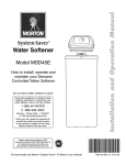
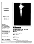
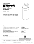
AUTOMATIC WATER FILTRATION
with high--flow 1” valve
Model AIF10
Automatic Iron and
Hydrogen Sulfide Filter
Installation D D Operation D D
Maintenance
D D Repair Parts D D
If you have questions when installing, programming, operating or maintaining this system
CALL TOLL FREE: 1---800---808---9899
Printed on recycled paper
ECODYNE WATER CONDITIONING, PO BOX 64420, ST. PAUL, MN 55164 -- 0420
1
Part No. 7320079 (Rev. A 5/12/10)
LIMITED WARRANTY
GENERAL CONDITIONS
Damage to any part of this water conditioner because of misuse, misapplication, neglect, alteration, accident, installation or operation contrary to our printed instructions, or damage caused by any unusual force of nature such as, but not limited to, freezing, flood,
hurricane, tornado, or earthquake is not covered by this warranty. In all such cases, regular parts and service charges will apply.
We assume no warranty liability in connection with this water conditioner other than specified herein. This warranty is in lieu of all
other warranties, expressed or implied, including warranties of fitness for a particular purpose. We do not authorize any person or
representative to assume for us any other obligations on the sale of this water conditioner.
This warranty gives you specific legal rights and you may have other rights which vary from state to state.
This water conditioner is manufactured by Ecodyne Water Conditioning, PO Box 64420, St.Paul, MN 55164 ---0420; customer service
telephone no. 1 ---800 ---808 ---9899.
WARRANTY POLICY
* ONE YEAR PARTS AND LABOR ON COMPLETE UNIT
*THREE YEARS LIMITED ON ELECTRONIC CONTROL
* TEN YEARS LIMITED ON MINERAL TANK, EXCLUDING MINERAL
SAFETY GUIDES
FOLLOW THE INSTALLATION INSTRUCTIONS CAREFULLY. FAILURE TO INSTALL THE CONDITIONER PROPERLY
VOIDS THE WARRANTY.
BEFORE YOU BEGIN INSTALLATION, READ THIS ENTIRE MANUAL. THEN, OBTAIN ALL THE MATERIALS AND
TOOLS YOU WILL NEED TO MAKE THE INSTALLATION.
CHECK LOCAL PLUMBING AND ELECTRICAL CODES. THE INSTALLATION MUST CONFORM TO THEM. Plumbing codes of Massachusetts shall be adhered to. Consult with your licensed plumber.
USE ONLY LEAD -- FREE SOLDER AND FLUX FOR ALL SWEAT---SOLDER CONNECTIONS, AS REQUIRED BY STATE
AND FEDERAL CODES.
USE CARE WHEN HANDLING THE CONDITIONER. DO NOT TURN UPSIDE DOWN, DROP, OR SET ON SHARP PROTRUSIONS.
DO NOT LOCATE THE CONDITIONER WHERE FREEZING TEMPERATURES OCCUR. DO NOT ATTEMPT TO TREAT
WATER OVER 120°F. FREEZING, OR HOT WATER DAMAGE VOIDS THE WARRANTY.
AVOID INSTALLING IN DIRECT SUNLIGHT. EXCESSIVE SUN HEAT MAY CAUSE DISTORTION OR OTHER DAMAGE
TO NON---METALLIC PARTS.
THE CONDITIONER REQUIRES A MINIMUM WATER FLOW OF 7 GALLONS PER MINUTE AT THE INLET. MAXIMUM
ALLOWABLE INLET WATER PRESSURE IS 125 PSI. IF DAYTIME PRESSURE IS OVER 80 PSI, NIGHTTIME PRESSURE MAY EXCEED THE MAXIMUM. USE A PRESSURE REDUCING VALVE IF NECESSARY. (ADDING A PRESSURE
REDUCING VALVE MAY REDUCE THE FLOW.)
THE CONDITIONER WORKS ON 24 VOLT-- 60 Hz ELECTRICAL POWER ONLY. BE SURE TO USE THE INCLUDED
TRANSFORMER.
UNPLUG THE FILTER FROM ELECTRICAL POWER BEFORE REMOVING OUTER VALVE COVERS, OR IF THE POWER
CABLE SHOULD BECOME DAMAGED OR FRAYED. MAKE REPAIRS AND REPLACE COVERS BEFORE PLUGGING
INTO THE POWER OUTLET AGAIN.
EUROPEAN DIRECTIVE 2002/96/EC REQUIRES ALL ELECTRICAL AND ELECTRONIC EQUIPMENT TO BE
DISPOSED OF ACCORDING TO WASTE ELECTRICAL AND ELECTRONIC EQUIPMENT (WEEE) REQUIREMENTS. THIS DIRECTIVE OR SIMILAR LAWS ARE IN PLACE NATIONALLY AND CAN VARY FROM REGION
TO REGION. PLEASE REFER TO YOUR STATE AND LOCAL LAWS FOR PROPER DISPOSAL OF THIS
EQUIPMENT.
2
UNPACKING / INSPECTION
The filter is shipped in one master carton and includes a potassium permanganate feeder assembly. The filter is completely assembled at the factory,
except as required at installation. The filter tank is
loaded with the proper quantity of manganese
greensand mineral, gravel and sand.
Be sure to check the entire filter for any shipping
damage or parts loss. Also note damage to the shipping cartons.
Small parts, needed to install the filter, are in a separate bag. To avoid loss of the small parts, keep them
together until you are ready to use them.
TABLE OF CONTENTS
PAGE NO.
WARRANTY, SAFETY GUIDES . . . . . . . . . . . . . . . . . . . . . . . . . . . . . . . . . . . . . . . . . . . . . . . . . . . .
SPECIFICATIONS, DIMENSIONS . . . . . . . . . . . . . . . . . . . . . . . . . . . . . . . . . . . . . . . . . . . . . . . . .
BEFORE STARTING INSTALLATION . . . . . . . . . . . . . . . . . . . . . . . . . . . . . . . . . . . . . . . . . . . . . .
TYPICAL INSTALLATION ILLUSTRATION . . . . . . . . . . . . . . . . . . . . . . . . . . . . . . . . . . . . . . . . . .
INSTALLATION STEPS . . . . . . . . . . . . . . . . . . . . . . . . . . . . . . . . . . . . . . . . . . . . . . . . . . . . . . . . . .
2
4
5
6
7
SANITIZING PROCEDURES . . . . . . . . . . . . . . . . . . . . . . . . . . . . . . . . . . . . . . . . . . . . . . . . . . . . . 7
PROGRAMMING THE FACEPLATE TIMER . . . . . . . . . . . . . . . . . . . . . . . . . . . . . . . . . . . . . . . . 11
GENERAL WATER FILTER MAINTENANCE . . . . . . . . . . . . . . . . . . . . . . . . . . . . . . . . . . . . . . . 13
TIMER FEATURES, SETTINGS, AND SERVICE . . . . . . . . . . . . . . . . . . . . . . . . . . . . . . . . . . . .
MANUAL ADVANCE DIAGNOSTIC . . . . . . . . . . . . . . . . . . . . . . . . . . . . . . . . . . . . . . . . . . . .
MANUAL INITIATED ELECTRONICS DIAGNOSTIC . . . . . . . . . . . . . . . . . . . . . . . . . . . . . .
WIRING SCHEMATIC . . . . . . . . . . . . . . . . . . . . . . . . . . . . . . . . . . . . . . . . . . . . . . . . . . . . . . . .
”QUICK---CHECK’ TROUBLESHOOTING PROCEDURE . . . . . . . . . . . . . . . . . . . . . . . . . .
15
17
18
18
19
REPAIR PARTS . . . . . . . . . . . . . . . . . . . . . . . . . . . . . . . . . . . . . . . . . . . . . . . . . . . . . . . . . . . . . . . . 20
3
SPECIFICATIONS / DIMENSIONS
Automatic Iron Filter -- AIF10
Type of mineral
manganese treated media (MTM)
Amount of mineral (cu ft)
1.0
Amount of gravel base (lbs)
17
Amount of filter sand (lbs)
10
Inlet water pressure limits (psi)
40 -- 125
Maximum water temperature (_F)
100
Minimum inlet water flow (gal/min)
7
Service flow rate (gal/min)
2 -- 5
Backwash flow rate (gal/min)
5
Inlet--outlet pipe size (inch)
1
Maximum iron removal (ppm)
20
Supply water minimum pH
7.0
Capacity rating
270 gallons with 10.6 ppm hydrogen sulfide (H2S)
620 gallons with 10.4 ppm ferrous iron FeSO4)
1900 gallons with 2.01 ppm manganese (MnSO4)
Well pump must be able to provide the minimum flow for 30+ minutes.
Contaminant Removal
Clear and/or Red Water Iron
Removes up to 15 ppm
Hydrogen Sulfide (rotten egg smell)
Removes up to 2 ppm
Manganese
Removes up to 5 ppm
10” dia. x 47” high
11”
B
49–3/4”
C
58–1/8”
INLET
A
14”
3 ---7/8”
OUT
Nominal Mineral Tank Size
INLET --- OUTLET
C
A
B
11”
DIA.
18”
4
BEFORE STARTING INSTALLATION
" WHERE TO INSTALL THE FILTER
S
S
S
Place the filter as close as possible to the pressure tank (well system) or water meter (city water).
freeze. Damage caused by freezing is not covered by the warranty.
Place the filter as close as possible to a floor
drain, or other acceptable drain point (laundry
tub, sump, standpipe, etc.). The drain point
must be able to discharge the backwash flow
rates shown on page 4.
Connect the filter to the main water supply pipe
BEFORE or AHEAD OF the water heater. DO
NOT RUN HOT WATER THROUGH THE FILTER. Temperature of water passing through the
filter must be less than 100_F (38_C).
S
Keep outside faucets on unfiltered water to conserve filtering capacity.
S
Do not install the filter in a place where it could
S
Put the filter in a place water damage is least likely to occur if a leak develops. The manufacturer
will not repair or pay for water damage.
S
A 120 volt electric outlet, to plug the included
transformer into, is needed within 10 feet of the
filter. The filter has an attached 10 foot power
cable. Be sure the electric outlet and transformer are in an inside location, to protect
from wet weather.
S
If installing in an outside location, you must take
the steps necessary to assure the filter, installation plumbing, wiring, etc., are as well protected
from the elements, contamination, vandalism,
etc., as when installed indoors.
S
Keep the filter out of direct sunlight. The sun’s
heat may soften and distort plastic parts.
" TOOLS, PIPE and FITTINGS, OTHER MATERIALS YOU WILL NEED (see page 6)
GDrain hose (5/8” inside diameter minimum), with a
garden hose connection on one end, is needed for
the valve drain (not included with this filter). See step
5 on page 9.
GPlastic inlet and outlet fittings included with the filter
allow water flow equivalent to 1” (nominal) copper
pipe. To maintain full valve flow, 1” pipes to and from
the filter fittings are recommended. Connect the
softener with pipe the same size as the water supply
pipe, or larger. Some local codes require a minimum
of 1” pipe size.
GIf a rigid valve drain is needed, to comply with
plumbing codes, you can buy the parts needed (see
page 8) to connect a 1/2 in. copper tubing drain.
GUse copper, brass, or galvanized pipe and fittings.
Some codes may also allow CPVC plastic pipe.
GPotassium permanganate is needed for regeneration of the filter mineral. It is available from most dealers of water conditioning equipment. This filter uses
from 2 to 5 ounces of potassium permanganate
each regeneration.
GALWAYS install the included bypass valve, or 3
shut-off valves. Bypass valves let you turn off water
to the filter for repairs if needed, but still have water
in the house pipes.
" PLAN HOW YOU WILL INSTALL THE FILTER
You must first decide how to run in and out pipes to
the filter. Look at the house main water pipe at the
point where you will connect the filter. Is the pipe soldered copper, glued plastic, or threaded brass/galvanized? What is the pipe size?
Now look at the typical installation illustration on
page 6. Use it as a guide when planning your particular installation. Be sure to direct raw, unfiltered
water to the filter valve inlet fitting. The valve is
marked IN and OUT.
5
TYPICAL SOLDERED COPPER or CPVC INSTALLATIONS
filtered
water
CROSS -- OVER
Use if water supply flows from the left.
Include single or 3 -- valve bypass.
unfiltered
UNFILTERED
water
WATER
FILTERED
WATER
FROM
FILTER
OUTLET
unfiltered water
to outside
faucets
TO FILTER
INLET
120 Volt
outlet
INSTALLATION USING 3 -- VALVE BYPASS
1” NPT sweat
adaptor (2)
not included
BYPASS
valve
OUTLET
valve
1” NPT installa-tion adaptor (2) *
INLET valve
o--ring seal (2) *
D for filtered water SERVICE:
- Open the inlet and outlet
valves.
- Close the bypass valve.
Bypass Valve *
clip (4) *
D for unfiltered water BYPASS:
- Close the inlet and outlet
valves.
- Open the bypass valve.
* included with filter -- Pipe and
fittings supplied by installer.
1” NPT sweat
adaptor (2)
not included
clip (2) *
1” NPT installa-tion adaptor (2) *
o--ring seal (2) *
VALVE
INLET
6
INSTALLATION STEPS
IMPORTANT SANITIZING PROCEDURES: Care is
taken at the factory to keep your water filter clean
and sanitary. Materials used to make the filter will not
infect or contaminate your water supply, and will not
cause bacteria to form or grow. However, during
shipping, storage, installing and operating, bacteria
could get into the filter. For this reason, sanitizing as
follows is suggestedz when installing.
FIGURE 1
clip (2)
A
plastic installation adaptors
(install in softener valve or
bypass valve)
OUTLET
support
A. Pour about 1 ounce of the following disinfectant
into the valve inlet fitting.
Common 5.25% household bleach (Clorox, Linco, Bo Peep, White Sail, Eagle, etc., brands)
INLET
B. Complete the santizing procedures in steps 7
and 10, pages 9 and 10.
z NOTE: Sanitizing is recommended by the Water Quality
Association for disinfecting. On some water supplies, they suggest periodic sanitizing.
clip (2)
bypass
valve
1. INSTALL BYPASS VALVE and/or PLASTIC
INSTALLATION ADAPTORS:
B
" Push the bypass valve, with lubricated o---ring
seals in place, into the valve inlet and outlet ports,
Figures 1A and 1C. Be sure the o---ring sealing surface is clean.
bypass valve or
plastic adaptor
clip
cross section of
valve inlet or outlet
--- AND/OR --" Slide plastic installation adaptors, with lubricated
o---ring seals in place, into the filter valve or bypass
valve inlet and outlet ports, Figure 1A. Be sure the
o---ring sealing surface is clean.
Note: Be sure the support is in place in the valve
outlet, as shown in Figure 1A.
" Snap the two large plastic clips in place, from the
top, down, Figures 1A and 1B. Be sure they snap
into place. Pull on the installation adaptors, or
bypass valve, to make sure they held securely in
place.
clip snaps into place
between larger diameter rings
Bypass Valve turned
downward for connection to floor level
plumbing.
C
2.
MOVE THE FILTER ASSEMBLY INTO
INSTALLATION POSITION:
" Be sure the installation surface is level and
smooth. If needed, place the tank on a section of
3/4” thick (min.) plywood. Then, place shims under
the plywood as needed to level the filter.
IN
7
o--ring
OUT
INSTALLATION STEPS
3.
4.
INSTALL GROUNDING CLAMP (IF
NEEDED):
PLUMB IN AND OUT PIPES TO AND
FROM FILTER:
NOTE: A 3---valve bypass system maintains ground
continuity.
CAUTIONS: Observe all of the following cautions
while you connect inlet and outlet plumbing.
" To maintain electrical ground continuity in the
house cold water piping, if the included single
bypass valve is used, install the included grounding
clamp.
" Turn off the house water supply valve and
open faucets to relieve pressure in the pipes.
" BE SURE RAW, UNFILTERED WATER IS DIRECTED TO THE VALVE INLET PORT.
" Be sure to use bypass valve(s).
FIGURE 2
ground clamp
" If making a soldered copper installation, do all
sweat soldering before connecting pipes to the
filter fittings. Torch heat will damage plastic parts.
" When turning threaded pipe fittings onto plastic
fittings, use care not to cross---thread.
" Use pipe joint compound on all external pipe
threads.
" Support inlet and outlet plumbing in some manner (use pipe hangers) to keep the weight off of the
valve fittings.
continued
inlet -- outlet pipes
FIGURE 3
drain fitting
PULL OUT
for filtered water
‘‘service’’
CONNECTING A RIGID VALVE DRAIN TUBE
To adapt a copper drain tube to the filter, buy a compression fitting (garden hose thread x 1/2”O.D. minimum tube)
and needed tubing from your local hardware store.
FIGURE 4
PUSH IN
for bypass
valve drain
hose
adaptor, garden hose
thread x compression
1/2” I.D.
(minimum)
copper tube
clip
drain fitting
To standpipe, sump, laundry
tub or other approved drain.
1--- 1/2”
air gap
1--- 1/2”
air gap
SUMP
1--- 1/2” air gap
valve drain
hose
STANDPIPE
LAUNDRY
TUB
1--- 1/2” air gap
FLOOR DRAIN
8
INSTALLATION STEPS
5.
CONNECT AND RUN THE VALVE DRAIN
HOSE:
FIGURE 5
nozzle assembly
" Take a length of 5/8” inside diameter garden hose
(not included) and attach to the valve drain fitting.
" Locate the other end of the hose at a suitable
drain point...floor drain, sump, laundry tub, etc.
Check and comply with local codes.
cover
IMPORTANT: Use high quality, thick---wall hose that
will not easily kink or collapse. The filter will not backwash properly if water cannot exit this hose during regenerations.
brinewell
cover
Refer to Figure 4 if codes require a rigid pipe drain
run.
5/16” tubing
" Tie or wire the hose in place at the drain point.
Water pressure will cause it to whip during the backwash and fast rinse cycles of regeneration. Also provide an air gap of at least 1---1/2” between the end
of the hose and the drain point. An air gap prevents
possible siphoning of sewer water, into the filter, if
the sewer should back up.
overflow
drain hose
brinewell
brine valve
(inside brinewell)
" If raising the drain hose overhead is required to
get to the drain point, do not raise higher than 8’
above the floor. Elevating the hose may cause a
back---pressure that could reduce backwash flow
and proper mineral bed cleaning.
TO FLOOR
DRAIN
6.
CONNECT THE POTASSIUM PERMANGANATE FEEDER (FIGURE 5):
" Run the 5/16” tubing from the brine valve, to the
nozzle assembly on the filter. Use slots in the tank
and both brinewells to hold tubing in place.
7.
FLUSH PIPES, CIRCULATE DISINFECTANT, EXPEL AIR FROM FILTER, AND TEST
YOUR INSTALLATION FOR WATER LEAKS:
" Attach a length of 3/8” or 7/16” I.D. drain hose
(7’ included) to the hose fitting on the tank sidewall.
Place the outlet of the hose over the floor drain. It is
a gravity drain, and must flow downward. Provide an
air gap as you did with the valve drain hose. CAUTION: Do not omit this hose. If the feeder tank
should overfill, the drain hose carries excess potassium permanganate solution to the drain. This solution will deeply stain anything it contacts.
" With brinewell covers in place, pour the included
2 lbs of potassium permanganate powder into the
feeder tank, then about 1/2 gallon water. Install the
tank cover.
CAUTION: To avoid water or air pressure damage
to filter inner parts, be sure to do the following
steps exactly as listed.
A. Fully open two cold, filtered water faucets
nearby the filter.
B. Place bypass valve(s) in ‘‘bypass’’ position. On
a single valve, slide the stem inward to BYPASS...see page 8. On a 3---valve system, close
the inlet and outlet valves, and open the bypass
valve...see page 6.
continued
9
INSTALLATION STEPS
C. Fully open the house main water pipe shutoff
valve. Observe a steady flow from both opened faucets.
" The filter works on 120 volt, 60 Hz electric power.
The included transformer changes standard 120 volt
AC house power to 24 volts. Plug the transformer
into a 120 volt outlet only. Be sure the outlet is always ‘‘live’’ so it can not be switched off by mistake.
D. Place bypass valve(s) in ‘‘service”, EXACTLY as
follows. KEEP FILTERED WATER FAUCETS OPEN.
1. SINGLE BYPASS VALVE: SLOWLY, pull the
valve stem outward to ‘‘service’’, pausing several
times to allow the filter to pressurize slowly.
9.
2. 3---VALVE BYPASS: Fully close the bypass
valve and open the outlet valve. SLOWLY, open
the inlet valve, pausing several times to allow the
filter to pressurize slowly. The sanitizing bleach
also circulates through the filter.
PROGRAM THE TIMER...see page 11.
10. Wait about 20 minutes after completing step
7, allowing bleach to sanitize. Then, press and hold
(for 3 seconds) the Touch---Hold button, to start an
immediate regeneration. This first regeneration
does several things.
E. After about three minutes, open a HOT water
faucet for one minute, or until all air is expelled, then
close.
S The potassium permanganate feeder fills with
water.
F. Close both cold water faucets.
G. Check your plumbing work for leaks and fix right
away, if any are found. Be sure to observe previous
caution notes.
S The mineral bed, inside the filter, is backwashed
with a fast upward flow of water. Mineral ‘‘fines’’
(too small or broken pieces) and remaining air
are flushed to the drain.
H. Turn on the gas or electric supply to the water
heater. Light the pilot, if applicable.
S Sanitizing bleach is purged.
8.
S A fast downward flow of water packs the mineral
bed to prepare it for iron and hydrogen sulfide
removal.
CONNECT TO ELECTRICAL POWER:
10
PROGRAMMING THE FACEPLATE TIMER
UP button
display
DOWN button
SELECT button
TOUCH--HOLD
button
" TIMER SETTINGS REQUIRED, upon installation, and after an extended power outage (see Power Outage
Memory, page 20).
When the transformer is plugged into the electrical outlet, a model code and a test number (example: J1.0),
begins to flash in the faceplate display. Then, 12:00 AM and PRESENT TIME begins to flash. Program the timer
as follows.
" SET PRESENT TIME OF DAY
If the words PRESENT TIME do not show in the display, press the
SELECT button until they do.
UP or
DOWN buttons to set the present time. Up moves the display ahead; down moves
Press the
the time backward. Be sure AM or PM, is correct.
Press buttons and quickly release to slowly advance the display. Hold for fast advance. This procedure applies
for all following settings.
Press the
SELECT button to set present time and advance to the next set up screen.
" SET DAYS TO RECHARGE
The default setting is 3 days. This means the filter will recharge every 3 days. See the chart on the following
page to determine the frequency of recharges. If a change is needed, use the
to set from 1 to 99 days between recharges.
UP or
DOWN buttons
continued
11
PROGRAMMING THE FACEPLATE TIMER
SUGGESTED DAYS BETWEEN RECHARGES
Find the number of people living in the household, and then going across the chart, find the amount of iron
(in parts per million) that is in the water supply. The number of days that shows is the number of days between
recharges the filter should be set for.
Number of
People
2
Iron (parts per million)
6
8
10
4
15
20
1
7 days
6 days
5 days
4 days
3 days
3 days
2 days
2
6 days
5 days
3 days
3 days
2 days
1 day
1 day
3
5 days
3 days
2 days
2 days
1 day
1 day
1 day
4
4 days
3 days
2 days
1 day
1 day
1 day
1 day
5
4 days
2 days
1 day
1 day
1 day
1 day
1 day
6
3 days
2 days
1 day
1 day
1 day
1 day
1 day
7
3 days
1 day
1 day
1 day
1 day
1 day
1 day
8
2 days
1 day
1 day
1 day
1 day
1 day
1 day
NOTE: If there is an iron bleed or the water supply has high turbidity (sand, silt, sediments, etc.) set the
filter to regenerate more often than the table above shows.
NOTE: In some extreme iron conditions, a fill setting of 2 minutes (3 ounces of potassium permanganate
used), or 3 minutes (4 oz.) could be needed for each regeneration.
NOTE: If hydrogen sulfide is present, decrease the number of days between recharges by one or more
(to a minimum setting of 1 day between recharges) until contaminant is removed.
Press the
SELECT button to set and advance to the next set up screen.
" SET RECHARGE TIME
The default setting is 12:00 AM. This is a good time if you have a water softener or another filter installed, the
recharge time should be offset to assure adequate water flow and pressure. For example, set the filter to start
backwash at 12:00 AM, or 4:00 AM, if the water softener is set to begin recharge at 2:00 AM.
If a change is needed, use the
Press the
UP or
DOWN buttons to set time.
SELECT button to set and return to the normal run display.
THE INSTALLATION AND PROGRAMMING STEPS ARE COMPLETE
NOTE: After you have completed all preceding instructions, your house water supply is filtered immediately.
However, your water heater is filled with unfiltered water and, as hot water is used, it will refill with filtered
water. When all the water is replaced in the water heater, all water will be filtered. If you want totally filtered water
immediately, drain the water heater after the regeneration initiated on page 10 is over (no water running from
filter drain hose). Drain until the water runs cold. If you do drain the water heater, use extreme care as the
hot water could cause severe burns.
12
GENERAL FILTER MAINTENANCE
" ADDING POTASSIUM PERMANGANATE POWDER TO FEEDER TANK . . . . . . . . . . . . . . . . .
It is very important to always have some potassium
permanganate powder in the feeder tank. If the filter
goes too long without a regeneration with potassium permanganate, the filtering mineral will lose it’s
manganese coating. Replacing the filter mineral bed
can be costly. Be sure to check the feeder tank every
2 ---4 weeks, and stir the potassium permanganate
powder to keep it from solidifying. Refill it with powder if less than an inch remains. After filling, check
the tank overflow drain hose to be sure it is over the
floor drain (see step 6, page 9).
regenerations needed each week. The answer is the
approximate number of weeks the potassium permanganate should last. The 2 minute fill setting uses
3 ounces of powder, and 3 minutes uses 4 ounces.
NUMBER OF FULL WEEKS 6 LBS OF
POTASSIUM PERMANGANATE POWDER LASTS
HOW LONG DOES THE POTASSIUM PERMANGANATE LAST? Using 2 ounces of powder each
regeneration (at 1 minute fill setting), 6 pounds of
potassium permanganate powder will last for about
48 regenerations. Divide 48 by the number of
FILL CYCLE MINUTES
no. of regenerations
each week
1
2
3
1
2
3
4
5
6
7
48
24
16
12
9
8
6
32
16
10
8
6
5
4
24
12
8
6
4
4
3
Note: The refill container has 6 lbs of potassium permanganate powder.
" CLEANING THE NOZZLE AND VENTURI ASSEMBLY . . . . . . . . . . . . . . . . . . . . . . . . . . . . . . .
A clean nozzle and venturi is needed for the filter
to work right. The nozzle/venturi creates the suction to move potassium permanganate solution
from the feeder tank to the mineral tank during regeneration. It will not work if it becomes plugged
with sand, silt, dirt, etc. The filter mineral will not be
properly cleaned, and oxidizing capacity restored.
Cap
O--ring Seal
Screen
Support
Screen
To get to the nozzle and venturi, remove the filter top
cover. Be sure the filter is in service cycle (no water
pressure at nozzle and venturi). Then, while holding
the nozzle & venturi housing with one hand, turn off
the cap. Lift out the screen support and screen, then
the nozzle and venturi. Wash and rinse the parts in
warm water until clean. If needed, use a small brush
to remove iron or dirt. Also check and clean the gasket.
Nozzle &
Venturi
Gasket
IMPORTANT: Be sure small
holes in the gasket are centered directly over the small
holes in the nozzle & venturi
housing.
*Flow Plug
Carefully replace all parts in the correct order. Be
sure holes in gasket align with holes in the housing.
Lubricate the o-ring seal with silicone grease and
place in position. Install and tighten the cap, BY
HAND ONLY. DO NOT OVER-TIGHTEN AND BREAK
THE CAP OR HOUSING.
Nozzle & Venturi
Housing
*INSTALL WITH NUMBERED
SIDE UP CONCAVE SIDE
DOWN.
" PROTECT THE FILTER FROM FREEZING . . . . . . . . . . . . . . . . . . . . . . . . . . . . . . . . . . . . . . . . .
If the filter is installed where it could freeze (summer
cabin, lake home, etc.), you must drain all water
from it to prevent possible freeze damage.
13
GENERAL FILTER MAINTENANCE
" CHECKLIST BEFORE YOU CALL FOR SERVICE . . . . . . . . . . . . . . . . . . . . . . . . . . . . . . . . . . .
PROBLEM
FILTER WILL NOT
REGENERATE
CAUSE
CORRECTION
manual plumbing bypass valve(s) in bypass
position
Refer to page 6, or to Figure 3, page 8 and
position for filtered water ‘‘service’’.
transformer unplugged at wall outlet, fuse
blown/circuit breaker popped, circuit
switched off
Check for loss of power and correct as needed. Reset the timer and use the RECHARGE
NOW feature, page 15.
timer set for vacation (VAC)
Press the Touch--Hold button once to return
the filter to service, see page 15.
timer not programmed for regerations, or
time to short
See pages 11 or 16 to set.
error code shows in timer display
Refer to page 16.
backwash flow control, drain hose restricted
or plugged, backwash flow less than 5 gpm
Check drain hose. Remove drain elbow on
filter valve to check flow control. See page 22
to check for correct assembly and orientation. Backwash flow should be 5 gpm or
higher.
nozzle assembly dirty
See page 13 to clean.
Adjust to a minimum of 20 psi.
LOW WATER PRESSURE AT well pump pressure switch set too low
HOUSE FAUCETS
regeneration needed more often to keep fil- See page 11 to set.
ter mineral clean
FILTERED WATER CONTAINS see all conditions above
IRON, SEDIMENT, DIRT, ETC.
too few regenerations programmed, or fill See page 11 to set.
time setting too short
feeder tank out of potassium permanganate
powder
See page 13 to refill.
hot water used while filter regenerates
The water heater will refill with unfiltered bypass water. See page 12.
possible increase in supply water iron content (common with some well water supplies)
Obtain a new water analysis and adjust the
regeneration schedule and/or fill cycle time.
leaking faucet or toilet valve
A small leak can waste hundreds of gallons
of water in a few days time. Fix all plumbing
leaks and always fully close faucets.
14
FACEPLATE TIMER FEATURES, SETTINGS AND SERVICE
NOTE: SEE PAGE 11 TO SET THE TIMER FOR THE CORRECT TIME OF DAY, DAYS OF REGENERATION
AND REGENERATION TIME.
NORMAL OPERATION, TIMER DISPLAYS . . . . . . . . . . . . . . . . . . . . . . . . . . . . . . . . . . . . . . . . . . . .
During normal operation, the
present time of day, and AM or
PM, show in the time display
area. When a regeneration
begins, RECHARGE NOW
starts to flash in the display,
along with the present time of
day.
RECHARGE
NOW
flashes until the regeneration
is over.
feature: RECHARGE NOW . . . . . . . . . . . . . . . . . . . . . . . . . . . . . . . . . . . . . . . . . . . . . . . . . . . . . . . . .
For times you expect to use
more water than usual, use
the RECHARGE NOW control. Press the Touch---Hold
button until RECHARGE NOW
begins to flash in the time dis-
play. A regeneration begins immediately. The filter
begins to filter your water again in about 2 hours.
NOTE: Avoid using HOT water during the regeneration, because the water heater will refill with unfiltered water.
feature: VACATION CONTROL . . . . . . . . . . . . . . . . . . . . . . . . . . . . . . . . . . . . . . . . . . . . . . . . . . . . . .
Before going on vacation, or
other long absence, press (do
not hold in) the Touch---Hold
button so VAC starts to flash in
the display. The timer continues to keep time, but will regenerations not occur to
waste water.
When you return, press the Touch---Hold button
again to return the filter to service, and the present
time in the display. REMEMBER TO DO THIS, or the
filter will not regenerate until you do.
NOTE: To shut off the water supply to the filter, use
the plumbing bypass valve(s).
feature: POWER OUTAGE MEMORY . . . . . . . . . . . . . . . . . . . . . . . . . . . . . . . . . . . . . . . . . . . . . . . . .
If electrical power to the timer is interrupted, the
2. The display will show a time, but it will be flashing.
“memory” built into timer circuitry keeps all settings
for 6 hours (minimum) or more. The display is blank
and the filter will not regenerate. When electrical
power comes on, one of two things will happen.
The timer memory did not keep the time settings
and they must be reset (page 11). The display returns to a flashing time, then begins to keep time
again. If you do not reset all time settings, the filter
will regenerate based on the days to recharge. However, regenerations will most likely be at the wrong
time of day.
NOTES:
The flashing display is to remind you to reset the
timer.
If the filter was regenerating when power was lost,
the valve will return to service position without finishing the cycle. Use RECHARGE NOW (see above) to
start another cycle if needed.
1. The present time of day will show, meaning the
timer memory has kept all settings.
NOTE: If the filter was regenerating when power was
lost, it will now finish the cycle.
15
FACEPLATE TIMER FEATURES, SETTINGS AND SERVICE
feature: ERROR CODES . . . . . . . . . . . . . . . . . . . . . . . . . . . . . . . . . . . . . . . . . . . . . . . . . . . . . . . . . . .
An error code could appear in
the faceplate display if a problem occurs in the filter. If you
see an error code, for exam-
ple Err03, instead of the present time of day, please
call your local dealer for service, or see your warranty on page 2.
CODE
POSSIBLE DEFECTS
Err01
Motor, Valve Position Switch
Err03
Motor, Valve Position Switch, Wire Harness
Err04
Valve Position Switch
Err05
PWA
TO REMOVE AN ERROR CODE: (1) unplug transformer (2) correct defect (3) plug transformer in (4) Do
the manual advance diagnostics. The error code will return within 12 minutes if the reason for the error code
was not corrected.
service: REGENERATION CYCLE TIME ADJUSTMENTS . . . . . . . . . . . . . . . . . . . . . . . . . . . . . . . .
The default settings for fill (1 minute, 30 seconds), solution draw/rinse (80 minutes), (backwash (20 minutes),
and fast rinse (5 minutes) cycles of regeneration are factory set for maximum performance of the filter. Use
the following procedures to check for correct cycle times, or to change if desired. However, only trained technicians should change the time settings.
service: ADJUSTABLE FILL TIME . . . . . . . . . . . . . . . . . . . . . . . . . . . . . . . . . . . . . . . . . . . . . . . . . . .
Press and hold the Select button until the display shows
“000--- ---”, then press the Select button once again to advance to the Fill time adjust
screen.
Using the Up or Down buttons
adjust the fill time from 0:00
minutes to 99:50 minutes
(zero to just under 1 hour and
40 minutes).
service: ADJUSTABLE DRAW/RINSE TIME . . . . . . . . . . . . . . . . . . . . . . . . . . . . . . . . . . . . . . . . . . .
Press and hold the Select button until the display shows
“000--- ---”, then press the Select button twice again to advance to the Draw/Brine/
Rinse time adjust screen.
Using the Up or Down buttons
adjust the brine/draw/rinse
time from 0 minutes to 255
minutes (zero to 4 hours and
15 minutes).
service: ADJUSTABLE BACKWASH TIME . . . . . . . . . . . . . . . . . . . . . . . . . . . . . . . . . . . . . . . . . . . . .
Press and hold the Select button until the display shows
“000--- ---”, then press the Select button three times to advance to the Backwash time
adjust screen.
Using the Up or Down buttons
adjust the backwash time
from 0 minutes to 60 minutes.
16
FACEPLATE TIMER FEATURES, SETTINGS AND SERVICE
service: ADJUSTABLE FAST RINSE TIME . . . . . . . . . . . . . . . . . . . . . . . . . . . . . . . . . . . . . . . . . . . . .
Press and hold the Select button until the display shows
“000--- ---”, then press the Select button four times to advance to the Fast Rinse time
adjust screen.
Using the Up or Down buttons
adjust the Fast Rinse time
from 0 minutes to 60 minutes.
service: MANUAL ADVANCE DIAGNOSTIC . . . . . . . . . . . . . . . . . . . . . . . . . . . . . . . . . . . . . . . . . . .
Use the following procedures to advance the filter
valve through the regeneration cycles to check operation.
2. To advance the valve, press the Touch---Hold button each time you want to move into the next cycle.
Remove top cover to observe valve rotation.
➡ Press the Touch---Hold button to move filter into
fill. Look into the feeder tank to verify fill water flow.
Note: Display must show time and day.
1. Press and hold the Select
button until the display shows
“000--- ---”.
a. If it does not move into fill, the valve motor is inoperative. Check all wiring and connections.
If valve is in service, fill. solution draw, backwash or fast
rinse (see markings on cam under motor), the display will show “000--- ---”, meaning the position
switch is open.
b. If water does not enter the feeder tank, see
‘‘Quick-Check’’ Troubleshooting.
➡ Press the Touch---Hold button to move filter into
solution draw. A slow flow of water to the drain begins. Verify solution draw from the feeder tank.
While the valve is rotating from one cycle to another,
the display will show “000---P”, meaning the position
switch is closed.
c. If solution level in the tank does not drop, see
‘‘Quick-Check’’ Troubleshooting.
➡ Press the Touch---Hold button to move filter into
backwash. Look for a fast flow of water from drain
hose.
An obstructed flow indicates a plugged top distributor, backwash flow plug, or drain hose.
position
markers
(valve in
service)
➡ Press the Touch---Hold button to move filter into
fast rinse. Again look for fast drain flow.
CAM
➡ To return softener to service, press the Touch--Hold button.
Note: While in manual advance, the time display will automatically return to the present time if a button is not
pressed within four minutes.
17
service: MANUAL INITIATED ELECTRONICS DIAGNOSTIC . . . . . . . . . . . . . . . . . . . . . . . . . . . . .
1. Press and hold the Select
button until the display shows
“000--- ---” to enter diagnostics.
Press the Up button to display
the number of days this face
plate has had electrical power
applied.
The letter (P) and dash(es) indicate POSITION switch operation. The letter appearing
means the switch is closed;
the dash means the switch is
open.
Press the Down button to display the number of regenerations initiated by this face
plate since the model code
number was entered.
Use the Touch---Hold button to manually advance
the valve into each cycle and check correct switch
operation.
CORRECT
SWITCH
DISPLAYS
2. Press the Select button and
hold in 3 seconds until a model code appears in the display.
VALVE CYCLE STATUS
-- --
Valve in service, fill, solution draw,
backwash or fast rinse position.
-- P
Valve rotating from one position to
another.
For correct filter operation, the model code number
must be HIF10.
To reset the code, press the Up or Down button until
the correct number shows.
While in this diagnostic screen, the following information is available and may be beneficial for various
reasons. This information is retained by the computer from the first time electrical power is applied to the
face plate.
3. Press Select to return the present time display. If
the code was changed, make ALL the timer settings,
pages 11 and 12.
service: WIRING SCHEMATIC . . . . . . . . . . . . . . . . . . . . . . . . . . . . . . . . . . . . . . . . . . . . . . . . . . . . . .
Back of Faceplate Timer PWA
120 V
Power
Source
Motor
ORANGE
24V
Transformer
GREEN
Position Switch
18
FACEPLATE TIMER FEATURES, SETTINGS AND SERVICE
service: ‘‘QUICK-CHECK’’ TROUBLESHOOTING PROCEDURE . . . . . . . . . . . . . . . . . . . . . . . . .
19
REPAIR PARTS -- FILTER ASSEMBLY
1
2
4
3
5
Valve Assembly
(see page 22)
6
7
9
8
10
11
12
13
14
15
16
17
18
20
KEY
NO.
PART
NO.
1
7259927
Wire Harness
2
7275907
Transformer, 24V --- 10VA
3
7286699
Repl. Timer (PWA)
4
7260554
Cover (order decal below)
--
7285279
Decal, Filter
5
7189449
Bottom Cover
6
7176292
Clamp Section (2)
7
7088033
Clamp Retainer (2)
8
7112963
O---ring Kit (incls. key no. 4, 5 & 6)
9
--- ---
O---ring, 2---7/8” x 3---1/4”
10
--- ---
O---ring, 13/16” x 1---1/16”
11
--- ---
O---ring, 2---3/4” x 3”
12
7088855
Top Distributor
13
7105047
Repl. Bottom Distributor
14
7092202
Mineral Tank, 10”
15
7266322
MTM, 1 cu ft
16
0501783
Filter Sand, 10 lbs
17
7124415
Gravel, 17 lbs
18
7302039
Tank Foot
DESCRIPTION
REPAIR PARTS -- FEEDER ASSEMBLY
KEY
NO.
PART
NO.
1
7071133
Tank Cover
2
0500283
Brinewell Cover
3
7113016
Tubing Assembly
4
7310155
Brine Valve Assembly (includes key
nos. 2, 4, 5 and 6)
5
7289710
Float, Stem & Guide Assembly
6
7142942
Clip
7
7116713
Clip
8
7082150
Wing Nut
9
7003847
O--Ring
10
7148875
Screw
11
7182390
Screen, Brinewell
12
7106962
Brinewell
13
7182421
Feeder Tank
14
1103200
Hose Adaptor
15
9003500
Grommet
DESCRIPTION
--
7161807
Tubing, 5/16” O.D. x 20’
--
7161768
Tubing, 5/16” O.D. x 100’
◆
7118252
Potassium Permanganate Powder
(6 lbs)
1
2
3
4
5
6
8
7
15
9
14
10
13
12
◆ not illustrated.
11
21
REPAIR PARTS -- VALVE ASSEMBLY
1
40
2
41
19
39
38
3
37
4
21
5
flow plug
assembly
6
assembled
view
36
34
9
35
33
10
32
11
31
12
13
7
8
43
wear--strip
14
seal
19
30
15
cross--section
view
29
28
27
16
17
18
20
21
26
25
24
22
42
23
22
REPAIR PARTS -- VALVE ASSEMBLY
KEY
NO.
PART
NO.
KEY
NO.
PART
NO.
1
7224087
Screw, #8-32 x 1” (2 req.)
26
1202600
Nut–Ferrule
2
7286039
Motor (incl. 2 ea. of Key No. 1)
27
7081201
Retainer
3
7231393
Motor Plate
28
7081104
Nozzle & Venturi Housing
4
7171250
Bearing
29
1148800
Flow Plug, .3 gpm
5
7283489
Cam and Gear
30
7114533
Nozzle & Venturi–Gasket Kit
6
7169180
Clip (Drain)
--
7204362
Gasket (only)
7
7172793
Drain Hose Adaptor
31
7146043
Screen
8
7170288
O-ring, 15/16 x 1--3/16
32
7167659
Screen Support
9
7178189
Flow Plug, 5 gpm
33
7170262
O--ring, 1--1/8 x 1--3/8
10
--
O-ring, 5/8 x 13/16 ◆
34
7199729
Cap
11
--
O-ring, 1--1/8 x 1--1/2 ◆
--
7085247
12
7174313
Bearing, Wave Washer
Nozzle & Venturi Asm. (incl. Key
Nos. 28 through 34)
13
7185500
Rotor & Disc
35
7175199
Wave Washer
14
--
O-ring, 4--1/2 x 4--7/8 ◆
36
7171161
Valve Cover
15
--
Rotor Seal ◆
37
7172997
Screw, #10 x 2--5/8 (8 req.)
16
--
Seal ◆
38
7305150
Switch
17
7171187
Plug (Drain Seal)
39
7140738
Screw, #4-24 x 3/4 (2 req.)
18
7129889
Spring
40
7214317
Bypass Valve (Incl. following parts)
19
7089306
Clip (4 req.)
--
7172882
Stem
20
7271204
Installation Adaptor, 1” (2 req.)
--
7173016
O--ring, 1.109 I.D. x 1.387 O.D.
(4 req.)
21
7170262
O--ring, 1--1/8 x 1--3/8 (4 req.)
--
7175238
C--ring
22
7078240
Support
41
0900857
Screw, #6-20 x 3/8 (3 req.)
23
7171145
Valve Body
42
7248706
Ground Clamp Kit
24
--
43
7104546
PVC Adaptor (2 req.), not included
25
7170319
◆
7185487
Seal Kit (incl. Key Nos. 10, 11, 14,
15, 16 and 24)
DESCRIPTION
Seal ◆
O--ring, 1/4 x 3/8 (2 req.)
◆ not illustrated.
23
DESCRIPTION