1
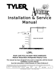
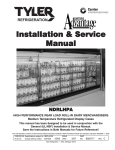
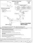
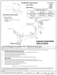
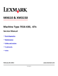
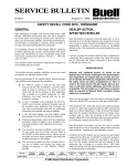
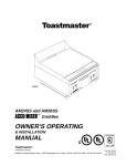
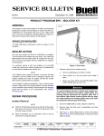
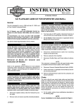
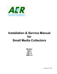
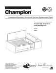
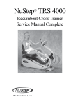
5
SERVICE BULLETIN
B-032
July 27, 2000
PRODUCT PROGRAM BP7 - EXHAUST HEADER MOUNT RETROFIT KIT
GENERAL
INSTALLATION
The purpose of this bulletin is to announce the release of a
new kit for all 1995-2000 S1, S1W, M2, S2/S2T, S3/S3T, and
X1 Model Buell motorcycles and to provide installation
instructions. Buell Motorcycle Company has developed this
kit as an upgrade to the exhaust header mounts currently in
use.
The kits will be available on or before 31 July, 2000. Kits must
be ordered as required and purchase price will be reimbursed
by warranty. See CREDIT PROCEDURES.
The life expectancy of this product program is one year from
the date of issue of this bulletin.
The following procedure applies to all models unless otherwise indicated.
Removing the Exhaust
1.
Secure motorcycle on a suitable lift.
1WARNING
To protect against shock and accidental start-up of vehicle, disconnect the negative battery cable before proceeding. Inadequate safety precautions could result in
death or serious injury.
NOTE
VEHICLES INVOLVED
All domestic and HDI 1995-2000 S1, S1W, M2, S2/S2T, S3/
S3T, and X1 Model Buell motorcycles.
The S1W and S1 negative battery cables were recalled under
safety recall #0811. If this recall service was not performed,
refer to Service Bulletin B-019INT and perform recall procedure before continuing.
2.
Disconnect negative battery cable from battery terminal.
NOTE
Lightning S1 and White Lightning S1W models have sidemounted voltage regulators and will not need to perform
steps 3 through 5. For S1 and S1W models, go to step 6.
DEALER ACTION
Follow the instructions provided to install the kit. See below
for list of Kit Contents:
3.
Remove voltage regulator from bracket.
a.
See Figure 1. Remove two socket head screws and
voltage regulator from bracket. Leave ground wire
connected to back of voltage regulator.
b.
Cut cable ties which secure voltage regulator wire
harness to oil pump fitting. Pull voltage regulator
connector [17] down from under gearcase cover.
c.
Cut cable tie that secures connector halves together
and disconnect connector [17].
d.
Remove ground wire and disconnect connector [17]
halves.
e.
Set aside any star washers that may be present
behind voltage regulator and/or bracket for reuse.
Exhaust Header Mount Retrofit Kit (Part No.
S1001.01A1)
Description
Quantity
Support, Header Assembly
1
Bracket, Voltage Regulator (not used
on S1/S1W models)
1
Washer, 5/16 (S1/S1W models only)
1
Spacer, Muffler Mount
1
Bracket, Muffler Mount (rear) - used on
1999-2000 Models Only
1
Screw, 5/16-18x1-1/2 Hex Head,
Grade 8
2
Locknut, metal 5/16-18
2
Cable Ties, Thick
3
ROUTING
SERVICE
MANAGER
SALES
MANAGER
PARTS
MANAGER
LEAD
TECHNICIAN
4.
See Figures 1 and 2. Remove (long) button head screw,
washer and metal locknut from voltage regulator mounting bracket. Discard long button head screw.
5.
Insert ball end allen wrench through screw hole and
remove short button head allen head screw, washer, and
metal locknut. Remove voltage regulator mounting
bracket from header support mount. Retain fasteners for
reuse.
TECHNICIAN
NO. 1
TECHNICIAN
NO. 2
TECHNICIAN
NO. 3
INITIAL HERE
©2000 Buell Distribution Corporation
TECHNICIAN
NO. 4
RETURN
THIS TO:
b0835x2x
Z Bracket (on all except
1996-98 S1, S1W,
S3/S3T and M2 Models)
*Washer
(S1/S1W Models Only)
* Bolts (2)
22-24 ft-lbs
(30-33 Nm)
*Rear Muffler
Mount Bracket
Header Support Mount
Bolts (2)
30-33 ft-lbs
(41-45 Nm)
* Header
Support Mount
Washer (2)
* Spacer
Washers (2)
Mount
Tabs
Metal
Locknuts (2)
* Grade 8 Bolt
22-24 ft-lbs
(30-33 Nm)
20-22 ft-lbs
(27-30 Nm)
Muffler
(all similar except
1995-96 S2/S2T)
Metal Locknut
* Voltage Regulator
Mounting Bracket (all except S1/S1W)
Washers (2)
Socket Head
Screws (2)
9-11 ft-lbs
(12-15 Nm)
Voltage
Regulator
Ground Wire
Bullet Connector
Connector [17]
*= Included in Kit
Figure 1. Modified Exhaust Mounting System (1999-2000 Models)
2 of 5
B-032
6.
7.
See Figure 3. Position bottle jack under swing arm
mount block and raise motorcycle just enough to unload
rear suspension (rear wheel remains on lift).
6750
Header Support
Mount Fasteners
Remove and discard header support mount from muffler
and crankcase.
a.
See Figure 2. Remove large button head allen
screw, two washers and metal locknut from header
support mount. Discard screw. Retain washers and
locknut for reuse.
Locknut,
Button Head
Screw (long)
NOTE
Earlier models have unthreaded front shock mounting brackets that used metal locknuts. Later models have the threaded
front shock mounting bracket and no locknuts.
b.
8.
See Figure 2. Remove two header support mount
bolts, washers, locknuts (if present) and header support mount, allowing shock mounting bracket
(attached to front shock eye) to hang free. Discard
header support mount. Retain washers and two
bolts.
Inspect muffler inlet, O2 sensor bung (if present), mounts
and fasteners for cracks or damage. Replace damaged
parts as required. See Credit Procedure.
Button Head Allen
Screw (Large)
Washers (2) and
Metal Locknut
Figure 2. Original Exhaust Header Mount (1999-2000)
b021r
NOTE
The Lightning S1 and S1W do not use the provided voltage
regulator bracket and instead use a washer between the
header support mount and crankcase. This washer is necessary to maintain the correct alignment of the header support
mount. For Lightning S1 and S1W Models, go to step 10.
9.
Flat Spot Under
Mount Block
Install new voltage regulator bracket to new header support mount and install to crankcase/muffler.
NOTE
Scraping the paint from the voltage regulator bracket is
required to ensure a good ground for the voltage regulator.
a.
See Figure 4. Scrape paint from inside corner of
voltage regulator bracket on crankcase side.
b.
See Figure 4. Position new header support so pin
engages hole in new voltage regulator bracket.
NOTE
Make sure voltage regulator ground wire remains behind voltage regulator bracket.
c.
See Figure 1. Apply LOCTITE THREADLOCKER
243 (Blue) to threads of two original header support
mount bolts. Install voltage regulator bracket/header
support assembly with two original header support
mount bolts and washers (and locknuts if present).
DO NOT tighten.
d.
Apply LOCTITE THREADLOCKER 243 (Blue) to
threads of original small button head allen screw
and install to voltage regulator bracket and shock
mounting bracket. DO NOT tighten.
e.
See FIgure 4. Check voltage regulator bracket to
verify that pin remains engaged in hole and that
bracket does not pivot front to rear.
10. S1/S1W Models Only: See Figure 1. Install new washer
(provided in kit) over hole at top of the header support
mount (between header support mount and crankcase).
Install header support mount with two original header
support mount bolts and washers.
B-032
Jack
Figure 3. Supporting Motorcycle with Jack
(Shock Absorber Removed for Clarity)
b0836x2x
Voltage Regulator
Mount Bracket
Pin/Hole
Header Support
Mount
Remove Paint
From Shaded Area
Figure 4. Voltage Regulator Bracket
3 of 5
11. See Figures 1 and 5. Install new grade 8 bolt, original
washer, new spacer, original washer and metal locknut
to header support mount. NOTE: Spacer goes between
front muffler mount tabs.
b0837x2x
*=Included in Kit
Header Support
Mount Bolt (reused)
)
*Header Support
Mount
NOTE
Step 12 only applies to 1999 and 2000 Models. Earlier Models have a welded rear mount and will not use the provided
rear mount. Go to step 13 if servicing a pre-1999 motorcycle.
12. 1999-2000 Models Only: See Figure 1. Remove and
discard muffler mount from rear of muffler and install
new muffler mount.
a.
Remove two screws, lockwashers and washers from
rear exhaust mount and Z bracket. Discard screws
and lockwashers. Retain washers for reuse.
b.
Push rear of muffler down slightly and remove (slide
off) and discard original rear muffler mount bracket.
c.
Slide new rear muffler mount bracket over muffler
and install with two new grade 8 bolts (provided in
kit), original washers and new metal locknuts.
NOTE: Install two metal locknuts over weldnuts on
right side.
d.
Tighten rear muffler mount bracket bolts to 22-24 ftlbs (30-33 Nm).
e.
Tighten rear muffler mount bracket metal locknuts to
20-22 ft-lbs (27-30 Nm).
*Voltage Regulator
Mount Bracket
*Bolt Grade 8
* Metal
Locknut
Washer
*Spacer
Washer
Figure 5. Header Support Mount (all except S1/S1W)
b0838x7x
*Voltage Regulator
Mount Bracket
Washers (2)
Screws (2)
13. Tighten header support mount fasteners.
a.
Tighten two header support mount bolts to 30-33 ftlbs (41-45 Nm).
b.
Tighten button head allen screw to 9-11 ft-lbs (12-15
Nm).
c.
Tighten front muffler mount bolt to 22-24 ft-lbs (3033 Nm).
Ground
Wire Bullet
Connector
* Header
Support Mount
Voltage
Regulator
Connector [17]
14. Lower and remove bottle jack from motorcycle.
NOTE
*=Included in Kit
Figure 6. Voltage Regulator Revised Mounting
For Lightning S1 and White Lightning S1W models proceed
to step 16.
15. See Figure 6. Install voltage regulator.
a.
Install voltage regulator to new bracket with original
socket head screws and washers. Tighten screws to
9-11 ft-lbs (12-15 Nm).
b.
See Figure 7. Route voltage regulator wire harness
between shock mounting bracket and oil line.
c.
See Figure 8. Mate connector [17] halves and
secure with cable tie.
d.
See Figure 6. Connect ground wire bullet connector
to main wire harness.
e.
See Figure 8. Push connector [17] behind gearcase
cover and secure connector [17] to oil pump fitting
with cable tie.
f.
See Figure 8. Secure voltage regulator wire harness
to oil line and oil pressure switch harness with cable
tie.
16. Reconnect battery negative cable to negative terminal.
Tighten terminal to specification given in service manual
for model being serviced.
4 of 5
b0840x7x
Oil Line
Voltage Regulator
Wire Harness
Oil Pressure
Switch Harness
Figure 7. Voltage Regulator Wire Harness Routing
B-032
CREDIT PROCEDURES DEALER STOCK PARTS
b0841x7x
*Cable Tie
Connector [17]
Remove and destroy all affected parts from your inventory.
To receive credit, complete a regular warranty claim referencing Service Bulletin B-032 in the “Description of Repair” section. Fill in the rest of the claim as follows.
*Cable Tie
Credit for Parts
Claim Type
*Cable Tie
Quantity
Oil Pump Fitting
Problem Part Nos.
*=Included in Kit
Figure 8. Cable Tie Locations
Part Description
CREDIT PROCEDUREVEHICLE REPAIR
After servicing each vehicle, file a warranty claim referencing
Service Bulletin B-032 in the “Description of Repair” or “Comments” section of the claim. Fill in the rest of the claim as follows:
BP7
Event 1, Qty & Problem
Part No.
0-65784-96YB
Event 1, Additional
(Replacement) Qty & Part No.
1-S1001.01A1
Part Description
See Note Below
65300-94Y
65784-96Y
65784-96YA
65784-96YB
* 65930-99Y
Header Support Mount
(1995-2000 Models)
* Rear Mount Bracket
(1999-2000 Models)
Customer Concern
Code
3201
Condition Code
3202
NOTE
“Quantity” may vary depending upon what you have in stock.
Credit for Labor
Claim Type*
BDS
Upon receipt of properly completed claim for parts in dealer
stock, you will receive the appropriate credit for parts.
Affected parts have been superseded. Remove and destroy
all affected parts from your inventory. Order parts as
required to restock your inventory.
Exhaust Header
Mount Retrofit Kit
Primary Labor Code
2660
Time:
1.0 hr (All Models)
Customer Concern Code
3201
Condition Code
3202
NOTE
●
If additional parts such as cable straps are required, list
them under Event 1, Additional Parts.
●
List any major components inspected in Step 8, found to
be defective and replaced under Event 1, Additional
Parts.
Use of incorrect claim type will cause claim to be suspended and/or be rejected and credit delayed.
B-032
●
5 of 5