1
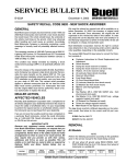
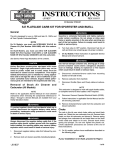
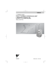
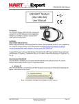
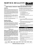
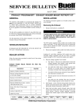
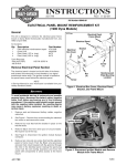
4
SERVICE BULLETIN
B-016
December 15, 1998
PRODUCT PROGRAM BP5 – ISOLATOR KIT
GENERAL
b0420x3x
The purpose of this service bulletin is to inform you that Buell
Motorcycle Company has developed an Isolator Kit (Part No.
91360-99Y) for motorcycles built prior to the 1999 model
year. This kit can be ordered to replace failed rear engine isolators and to prevent future failures of the isolators.
1 TON
3/4 TO
N
VEHICLES INVOLVED
All 1996-1998 Buell motorcycles could be subject to this
condition.
DEALER ACTION
The new rear Isolator Kit (Part No. 91360-99Y) is available.
The kit includes two isolators and two shims. Only install the
new isolators with the raised letter “B” molded into the side.
Do not use the old isolator, Part No. 47680-94Y, for replacement purposes.
If a customer comes in with torn isolators on a pre-1999
model year motorcycle, inspect isolators prior to disassembly
to verify that the isolators are actually torn.
Figure 1. Floor Hoist
1.
NOTE
If an isolator’s paint coating is cracked, it may give the false
impression that the isolator itself is damaged. Inspect each
isolator carefully and order an Isolator Kit (Part No. 9136099Y) only for vehicles with torn isolators.
In the interest of customer satisfaction, if your customer experiences a failure with the old-style isolators, the new isolators
can be installed under warranty. Vehicles beyond the warranty
period will not require a prior authorization. See CREDIT
PROCEDURES.
REPAIR PROCEDURE
Isolator Removal
●
●
NOTE
Perform the following procedures according to the guidelines given in the service manual for the particular model
and year being serviced.
Mark all hardware as it is removed so that it may be
returned to it’s original location.
ROUTING
SERVICE
MANAGER
SALES
MANAGER
PARTS
MANAGER
LEAD
TECHNICIAN
Prepare motorcycle for isolator service.
a.
Remove saddlebags on S2T/S3T models.
b.
Place vehicle on a lift and anchor front wheel in
place.
c.
Raise rear wheel off lift using REAR WHEEL SUPPORT STAND (Part No. B-41174).
1WARNING
To avoid accidental start-up of vehicle and possible personal injury, disconnect the battery cables before proceeding. Always disconnect the negative cable first. If
the positive cable should contact ground with the negative cable installed, the resulting sparks may cause a battery explosion producing personal injury.
2.
Disconnect both battery cables, negative cable first.
3.
Remove seat, fuel tank cover (if applicable), fuel tank
and tail section.
4.
See Figure 1. Attach lifting straps to a floor hoist placed
behind the lift. Connect lifting straps to motorcycle frame
tubes as shown.
TECHNICIAN
NO. 1
TECHNICIAN
NO. 2
TECHNICIAN
NO. 3
INITIAL HERE
©1998 Buell Distribution Corporation
TECHNICIAN
NO. 4
RETURN
THIS TO:
CAUTION
b0702xsb
Remove oil filter before raising frame. Without removal,
oil filter will be damaged during procedure.
5.
Remove cap from oil tank. Drain oil tank and remove oil
filter.
6.
Remove rear fender.
7.
Remove rear brake caliper assembly. Support caliper
from frame with rope.
8.
Label and detach feed, vent and return hoses from oil
tank.
9.
Remove left rider footrest from footrest mounts.
10. Remove shift linkage, taking care not to scratch primary
cover.
11. Remove air cleaner cover and backplate. This includes
removing right side fairing lower on S2T/S3T models.
12. Remove carburetor, exhaust header and muffler.
13. Remove sprocket cover.
4
1
2
1.
2.
3.
4.
3
Isolator bolt
Washer
Isolator
Frame mounted locating pin
Figure 2. Isolator Assembly Before Installing Kit
14. Unplug all wires which do not have adequate slack to
support raising frame above engine. These will include:
a.
Neutral indicator wiring.
b.
Cam position sensor connector.
c.
Relay terminal on starter.
d.
Oil pressure switch lead.
e.
Voltage regulator wiring.
f.
V.O.E.S. wiring.
Pin
15. Remove any restrictive cable straps from wiring harness
and oil lines. Note cable strap locations for reinstallation
upon assembly. All wires and hoses must have adequate
slack when frame is raised and all oil and vent lines must
not be pinched.
16. Place a crating strap between the engine cylinders and
around the lift. Tighten crating strap until snug.
17. Detach rear tie bar and chassis ground strap from frame.
Do not remove tie bars from engine.
18. See Figure 2. Remove isolators bolts (1) and washers (2)
on each side.
19. Slowly raise floor hoist until rubber isolators (3) can be
removed. Frame will rise while engine and swingarm
remain secured to lift by crating strap.
0.080-0.120 in.
(2.032-3.048 mm)
20. Remove rubber isolators.
Isolator Pin Inspection
See Figure 3. After disassembly, inspect frame mounted
locating pins. Pins must extend from frame between 0.0800.120 in. (2.032-3.048 mm).
●
If pin length is within limits, continue with installation of
new isolators and shims.
●
If pin length is greater than specification, carefully file
end of pin until it falls within specification. File perpendicular to pin end. Pin must not have any sharp or uneven
edges which could tear rubber isolator upon installation.
2 of 4
Figure 3. Locating Pin Inspection
Isolator Installation
b0702xsb
CAUTION
4
Isolator bolts must be tightened within 30 minutes of
applying LOCTITE THREADLOCKER. Failure to tighten
bolts within 30 minutes may cause LOCTITE to set.
1.
a.
2.
1
See Figure 4. Prepare isolator hardware for installation.
Place isolator shim (5) next to swingarm mount
block.
b.
Insert new rubber isolators (3) in place. Align metal
pin on frame (4) and hole in isolator.
c.
At this time, apply LOCTITE THREADLOCKER 262
(red) (Part No. 94759-99) to isolator bolt threads (1)
and LOCTITE ANTI-SEIZE to bottom of isolator bolt
head.
Lower floor hoist and guide frame over swingarm mount
block.
5
2
1.
2.
3.
4.
5.
3
Isolator bolt
Washer
Isolator, revision B
Frame mounted locating pin
Shim
Figure 4. Isolator Assembly After Installing Kit
CAUTION
●
Use caution when installing isolator bolts. Bolts may
be easily cross threaded.
●
Observe seam on rubber isolator after isolator bolt is
tightened. If seam twists, apply more LOCTITE ANTISEIZE to underside of isolator bolt heads.
●
Do not overtighten isolator bolts. Too much torque
may lead to premature isolator failure.
3.
As frame lowers, install isolator bolts.
a.
Place washer (2) over isolator bolt. Install assembly
through isolators and into the swingarm mount
block.
b.
Tighten to 100-110 ft-lbs (135.6-149.1 Nm).
c.
See Figure 5. After tightening isolator bolts, verify
that seam on isolators is perpendicular to swingarm
mount block. If seam is not perpendicular loosen
isolator hardware and realign.
4.
Install tie bars and chassis ground strap. Tighten tie bar
hardware to 30-33 ft-lbs (40.7-44.7 Nm).
5.
Install carburetor, air cleaner assembly and exhaust system. This includes installing right side fairing lower on
S2T/S3T models.
6.
Reconnect all disconnected wires except battery cables.
7.
Install shift linkage and left rider footrest.
8.
Attach oil tank hoses and fill lubrication system. Consult
a service manual for oil type and amount.
9.
Install new cable straps around wiring and oil lines as
needed.
b0674x2x
Isolator
Seam
Straight seam
(correct)
Twisted seam
(incorrect)
Figure 5. Isolator Alignment
3 of 4
1WARNING
Always test motorcycle brakes at low speed after servicing or bleeding system. To prevent personal injury, Buell
recommends that all brake repairs be performed by a
Buell dealer or other qualified mechanic.
10. Install rear brake caliper assembly.
11. Install rear inner fender.
1WARNING
CREDIT PROCEDURES
After servicing each vehicle, file a warranty claim referencing
Product Program BP5 in the “Description of Repair” or “Comments” section of the claim. Fill in the rest of the claim as follows:
Table 1. Product Program BP5
Claim Type*
BMC, BGW
Event 1, Qty & Problem
Part No.
0-47564-86
After installing seat, pull upward on front of seat to be
sure it is locked in position. If seat is loose, it could shift
during vehicle operation and startle the rider, causing
loss of control and personal injury.
Part Description
12. Install tail section, fuel tank, fuel tank cover (if applicable)
and seat.
Primary Labor Code
1WARNING
Always connect positive battery cable first. If the positive
cable should contact ground with the negative cable
installed, the resulting sparks may cause a battery explosion resulting in personal injury.
13. Connect both battery cables, positive cable first.
14. Remove motorcycle from lift. Install saddlebags on S2T/
S3T models.
15. Check oil level after starting vehicle and allowing motorcycle to reach operating temperature.
1WARNING
Check for proper brake lamp operation before riding
motorcycle. Visibility is a major concern for motorcyclists. Failure to have proper brake lamp operation could
lead to personal injury.
16. Turn ignition key switch to IGN. Apply rear brake pedal to
test brake lamp operation. Turn ignition key switch to
LOCK.
4 of 4
Event 1, Additional
(Replacement) Qty & Part No.
1-91360-99Y
Rear Isolator Kit
2375
Time: S2T/S3T Models
3.1
Time: All Other Models
2.8
Customer Concern Code
9203
Condition Code
2101
*Use BMC if vehicle is still within factory warranty period; use
BGW if vehicle is beyond factory warranty period. Vehicles
beyond factory warranty period do not require prior authorization for this product program.
NOTE
If additional parts such as cable straps are required, list them
under Event 1, Additional Parts.