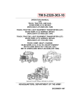
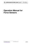
1
MOONEY NAVIGATION COUPLER
OPERATION & SERVICE INSTRUCTIONS MANUAL
No. 11990-1
BRITTAIN INDUSTRIES, INC.
TULSA, OKLAHOMA
Issue A
5/31/01
.
TABLE OF CONTENTS
Title
PARAGRAPH
PAGE
1
1
1.3
1.4
1
3
Navigation Radio Requirements
2
4
Survey of Autopilot Installation
3
6
3.1
3.2
3.3
7
7
7
4
8
Heading Gain Adjustment
VOR Gain Adjustment
Magnetic Heading Compensation
Heading Dial Adjustment
4.4
4.6
4.8
4.9
8
10
10
13
Operational Flight Check & Adjustments
5
13
5.1
5.2
5.3
5.4
13
13
14
14
Emergency Procedures
6
15
Returning Aircraft to Service
7
15
Location of Field Adjustments
-
16
Zone Chart
-
17
Theory of Operation
Magnetic Heading Control
Radio Navigation Coupling
Airframe Requirements
Electrical System Requirements
Radio Navigation Coupling
Pre-Flight Adjustments
Pre-Flight Checks
Functional Operation
Rate of Turn
Directional Control
INTRODUCTION
The purpose of this manual is to assist service and maintenance personnel in
testing and calibration of the Nav-Coupler/Heading Lock System. This manual is
concerned primarily with the Nav-Coupler/Heading Lock System.
It is imperative that the "Positive Control" System is functioning properly before
the ground and flight test procedures outlined in this manual are completed.
This manual was automated on May 31, 2001. Changes were made only to
correct typographical errors and to clarify content.
11990-1
Page 1
1.
THEORY OF OPERATION
1.1
In the Nav-Coupler/Heading Lock System, the directional control of the
aircraft is obtained by means of an electro-pneumatic servo valve. This
servo provides vacuum to command aileron and rudder control.
Variations in the voltage operating the servo valve are produced in the
Controller/Amplifier Assembly. This is accomplished by means of Sensor
and Radio Navigation equipment. In addition, a Heading Select Knob,
located on the Controller Amplifier operates the Servo Valve for
maneuvering of the aircraft.
1.2
Rate of turn depends upon proper basic system operation. For this reason,
it is essential that the roll/yaw stabilizing system be correctly adjusted.
Refer to Operation and Service Manual 11990 to verify proper operation
of the basic system.
1.3
Magnetic Heading Control
Magnetic heading information is obtained by means of a Magnetic
Heading Sensor. When the heading azimuth on the controller is set to 90°
and the aircraft is on a heading of 90°, the electrical circuit is balanced.
When the controller heading azimuth is rotated to 180°, electrical
imbalance is generated. This imbalance produces an error signal that is
amplified in the amplifier section. The amplified signal generates voltage
on the right side of the Servo Valve, causing it to open. With the valve
open, the aircraft turns right until the error signal is removed by the
Heading Sensor. When the aircraft assumes a heading of 180°, the
Magnetic Sensor and the heading azimuth are in phase and the voltage at
the servo valve drops to zero.
When the heading azimuth and the electrical output of the magnetic sensor
are in phase, any change in the heading of the aircraft to right or left will
produce an error signal from the sensor. This signal will cause the valve
to be rotated to the right or left to bring the aircraft back to the point where
no error is generated at the sensor.
11990-1
Page 2
1.
THEORY OF OPERATION (CONTINUED)
1.3
Magnetic Heading Control (Continued)
The magnetic heading sensor is remotely mounted in the aircraft similar to
a remote indicating compass. The sensor has no moving parts and requires
no servicing.
The sensor installation is designed to permit the unit to move freely as a
pendulum on the longitudinal axis of the aircraft. Acceleration and
deceleration of the aircraft displaces the sensor on its pivots and may
produce momentary changes in magnetic headings on East and West.
Improper dressing of the sensor harness, causing a restriction of the
pendulous motion, will exaggerate this heading error.
There is a definite relationship between the rate of turn and programmed
magnetic headings. The circuitry providing magnetic heading information
is designed for "roll out" characteristics that assume a given rate of turn.
If this rate is greater than 3° per second, there will be a tendency for the
aircraft to over-shoot programmed magnetic turns to East, North and West.
Proper rate of turn should allow for approximately 5° over-shoot on East
and West, with less than 5° over-shoot on North and South.
Unequal turns to left and right may be caused by improper rigging of the
aircraft. If an aircraft is rigged to fly with one wing down, or with the ball
of the Turn Coordinator off center, turns will be steeper in one direction
than the other. Proper rigging may be determined only when the Positive
Control System is shut off.
In all magnetic airborne devices, there are certain inherent errors caused by
the vertical component of the earth's magnetic field. To minimize the
undesirable effect of the vertical component, there are compensating
transistorized networks in the system. The amount of compensation
produced may be varied by positioning the "zone selector" on the
Controller/ Amplifier Assembly. Make certain that the zone switch is set
to correspond with the positions indicated on the map showing the selector
zones (See Diagram II).
11990-1
Page 3
1.
THEORY OF OPERATION (CONTINUED)
1.4
Radio Navigation Coupling
Radio VOR coupling is obtained by means of additional circuits in the
amplifier. These circuits are connected to the VOR meter output of the
navigational equipment. When the VOR deviation is to the right (in
yellow zone), the electro-pneumatic servo valve is rotated to the right,
commanding a right turn. When the VOR deviation is to the left (in the
blue zone), a left turn is commanded. The voltage generated in the VOR
system also modulates the Nav-Coupler.
Omni heading intercept and hold is accomplished by selecting the desired
VOR radial with the OBS selector of the navigational equipment. The
Omni radial is matched by selecting the same heading on the rotatable
heading azimuth. When the aircraft is not on the selected VOR radial, the
VOR meter will be displaced from the center position. This displacement
represents a bi-polar meter voltage, causing the servo valve to open until
the voltage is zero. When the meter voltage becomes zero, the aircraft will
continue to fly on the magnetic heading selected on the heading azimuth. .
The relationship of heading to navigation information varies in the Capture
and Track modes. In the Capture mode, a full scale VOR meter deviation
will produce a heading change as great as 45° from a selected magnetic
heading. As the desired VOR radial is approached, meter displacement
decreases and the aircraft will gradually turn toward the selected magnetic
heading. In the Capture position, a VOR error signal equal to 1° off
course will cause a change in selected heading of 5°. Maximum bank
angle in the Capture mode is a standard rate turn.
The system is more sensitive to the VOR meter displacement in the Track
mode. This optimizes the tracking of a captured omni radial. The bank
angle in the Track mode is one-third of the maximum bank angle obtained
in the Capture mode.
11990-1
Page 4
1.
THEORY OF OPERATION (CONTINUED)
1.4
Radio Navigation Coupling (Continued)
Added circuitry in the Track mode optimizes station crossing where the
navigation signal shifts phase. The Track mode effectiveness of the VOR
signal is limited to a maximum of 5° displacement. When the VOR needle
exceeds 5° off course, magnetic heading data supersedes radio navigation
information, precluding rapid and excessive heading excursions over a
VOR station.
2.
NAVIGATIONAL RADIO REQUIREMENTS FOR AUTOPILOT COUPLING
2.1
The Autopilot is designed to accept an impedance load of 10,000 ohms.
The intercept circuitry of the Nav-Coupler is floating with respect to
ground. Optimum Autopilot response is obtained with as little as 35
millivolts across the VOR meter circuit for 10° off course. (Bi-polar
voltage up to 150 millivolts is acceptable and may be attenuated by the
amplifier nav sens adjustment.) By reason of these characteristics, the
Nav-Coupler is compatible with most navigation radio equipment.
2.2
There are considerable differences in the electrical characteristics of radio
navigation equipment of various models and makes. They are divided into
two categories: ARINC Standard and non-ARINC Standard equipment.
A.
Radio navigation equipment meeting ARINC Standards has
provisions for three or more 1,000 ohm loads. Autopilot coupling
may be connected across the VOR meter output without changing
existing loads. All ARINC Standard equipment will provide
adequate signal levels for optimum Autopilot Nav-Coupler
operation
11990-1
Page 5
2.
NAVIGATIONAL RADIO REQUIREMENTS FOR AUTOPILOT COUPLING (CONT'D)
2.2
(Continued)
B.
Radio navigation equipment not designed to ARINC Standards
may be used, in most instances, with the Autopilot Coupler system.
Some of the equipment in this category requires no circuit
modification to connect the Nav-Coupler to the VOR meter. There
is considerable radio navigational equipment that does not provide
sufficient signal output for operating the Autopilot Coupler. Prior
to ground check procedure, determine whether the existing radio
equipment is compatible with the Nav-Coupler. Determine if a
bi-polar voltage across the VOR meter of 35 millivolts minimum
for 10° off course, is present.
Radio equipment compatibility in this group is also. determined by
a ground check procedure wherein navigation error information is
balanced against magnetic heading information. If there is any
question regarding the respective radio compatibility, the
information in 2.1 should be transmitted to the appropriate radio
equipment manufacturer for recommendations.
2.3
Some VOR units have a floating ground in the indicator circuit. Coupling
to the Autopilot (also floating with respect to ground) may result in
overloading of the Autopilot amplifier circuits. Loading may result in an
offset of the servo valve in the amplifier shown by a voltage differential
across the yellow and orange test jacks when the VOR equipment is
energized. Loading of the amplifier may be corrected by placing a ground
connection or jumper between lead #3 of the cable assembly and the
chassis of the VOR converter.
11990-1
Page 6
2.
NAVIGATIONAL RADIO REQUIREMENTS FOR AUTOPILOT COUPLING (CONT’D)
2.4
The Autopilot Nav-Coupler is capable of responding to minute deviations
of the VOR indicator. This sensitivity level is necessary to obtain
optimum Omni capture and track performance. Make certain the radio
navigation equipment is functioning properly, and that the VOR needle is
steady. The use of an Omni Simulator or Omni Station capable of
producing a full scale meter deflection is recommended. With needle
centered, check for erratic needle movement. This must be at a minimum.
Check generator and voltage regulator. Make certain they are sufficiently
filtered to minimize electrical interference. Check Omni course width and
sensitivity to equipment manufacturer's specifications.
NOTE:
3.
The Autopilot equipment must respond to the electrical
information appearing on the VOR meter. If this
information is inaccurate, undesirable Autopilot coupling
will result.
2.5
Verify that the aircraft's voltage regulator is producing the proper voltage.
This check should be made with a maximum electrical load applied and a
fully charged battery. (Low voltage will result in sub-standard operation
and a decreased rate of turn.) After installation of the Nav-Coupler, it must
be determined that the operation of the radio navigation equipment meets
the radio manufacturer's minimum performance specifications, using
specifications and procedures specified in the radio manufacturer's service
and maintenance manual.
2.6
Wires #3 and #4 from the controller harness are to be connected in parallel
to the left/right meter movement of the VOR/LOC Indicator. An optional
double-pole double-throw switch may be installed to enable the pilot to
switch the Nav-Coupler from the #1 VOR to #2 VOR if desired. The
output from the two Omni converters must be equal or mismatching will
occur.
SURVEY OF AUTOPILOT INSTALLATION & BASIC REQUIREMENTS
The purpose of this section is to furnish a procedure for verifying proper
installation and function of the Autopilot components and system.
11990-1
Page 7
3.
SURVEY OF AUTOPILOT INSTALLATION & BASIC REQUIREMENTS (CONT’D)
3.1
Airframe Requirements
Prior to installing the flight control equipment, the aircraft should be flown
to determine whether the basic "Positive Control" system is
properly operating. Refer to manual 11990 for proper operation of the
basic system.
The following items must be verified for proper operation before
proceeding with the ground adjustment procedures:
A.
B.
C.
D.
3.2
Primary vacuum setting
Cut-off valve operation
Pilot valve operation
Proper airframe rigging
Electrical System Requirements
The sensor should be installed in an area that is free of magnetic fields.
Proximity to a power supply, remote indicating compass, etc., may result
in magnetic variations which cannot be compensated. Such interference,
although uncommon, may result from locating the sensor in the proximity
of a VHF antenna.
Lead #1 is system ground, make certain this lead is not connected with any
other ground lead.
3.3
Radio Navigation Coupling
Determine the compatibility of the navigational radio equipment according
to the radio compatibility chart, found in the installation manual.
Temporarily connect leads #3 and #4 of the cable assembly to the VOR
indicator until proper left/right phasing has been determined. Refer to the
installation manual for proper pin connections.
11990-1
Page 8
4.
PRE-FLIGHT ADJUSTMENTS
Use the following ground-test procedure to determine that the electrical and
vacuum portions of the equipment are functioning properly before flight testing is
attempted.
4.1
To perform the ground-test adjustments, it is necessary to partially remove
the Controller/Amplifier from the instrument panel. Turn the latching
screw counter clockwise until the latch is disengaged. Diagram I shows
the location of the latching screw and the controls to be adjusted during
ground-test.
4.2
Pull the Controller/Amplifier approximately one-half way out of the
instrument panel for access to the controls. Connect a 10,000 Ohm per
volt voltmeter to the orange and yellow test jacks located in the lower
right front corner of the Controller/Amplifier. Set the voltmeter to the 10
or 12 volt D.C. range.
CAUTION
The hemisphere switch should be set to the intermediate "T" (test) position
and the zone switch should be set to the proper zone number.
4.3
The following adjustments are to be made with the aircraft on the compass
rose. Have the aircraft running with all electrical equipment turned on.
4.4
Heading Gain Adjustment
Adjust the HDG dial to the aircraft heading, as indicated by zero volts on
the D.C. voltmeter. Turn the HDG dial to a heading of + 30° from the
previously determined heading. From the-map shown on Diagram II,
determine the position of the aircraft within its zone. Adjust the HDG
gain control shown in Diagram I until the voltmeter reading corresponds to
that shown in Figures 1 & 2 for the appropriate aircraft location within the
zone.
11990-1
Page 9
4.
PRE-FLIGHT ADJUSTMENTS (CONTINUED)
4.5
Heading Gain Adjustment (Continued)
AIRCRAFT POSITION WITHIN
MAGNETIC ZONE
OUTPUT VOLTAGE FOR ± 30
HEADING ERROR
Southern Boundary
6.8 Volts
Southern Quarter
6.4 Volts
Center
6.0 Volts
Northern Quarter
5.7 Volts
FIGURE NO. 1
FIGURE NO. 2
11990-1
Page 10
4.
FLIGHT ADJUSTMENTS (CONTINUED)
4.6
VOR Gain Adjustment
Make certain that the VOR Receiver and Converter-Indicator are operating
properly and meet the manufacturer's specifications. The performance of
the navigation coupler is dependent upon the quality of the signal from the
VOR Converter.
4.7
Use a VOR simulator or a very strong, steady station signal. Connect the
D.C. voltmeter to the test jacks. Place the mode selector switch in the
"HDG" position. Set the OBS on the VOR Indicator to a 5° bearing error.
Set the "HDG" dial to the aircraft heading, as indicated by zero output on
the voltmeter. Turn the mode switch to the "CAP" position. Adjust the
nav pot until a reading of 5 volts is obtained on the voltmeter.
NOTE:
4.8
It is necessary to adjust the gain control and heading dial
slowly in order to obtain accurate settings.
Magnetic Heading Compensation
To compensate the Magnetic Heading Sensor the same technique is used
as in compensating the primary aircraft compass. Rotation of the E-W
adjustment clockwise or counter-clockwise will bend East and West
headings both towards North or South.
Example:
11990-1
Page 11
4.
PRE-FLIGHT ADJUSTMENTS (CONTINUED)
4.8
Magnetic Heading Compensation (Continued)
Rotation of the N-S adjustment clockwise or counterclockwise will bend
both North and South towards East or West. Example:
Example #1: A reading of 085° east and 275° West would necessitate
rotating the E-W adjustment to bend both East and West 5°
towards South, bringing west to 270° and East to 090°.
Example #2: North is 355° and south is 185°. Rotate the N-S
adjustment to bend both North and South towards East 5°,
bringing north to 0° and South to 180°.
Adjustments for magnetic heading should be made according to the
following sequence.
A.
Use a compass rose or a master compass. Align aircraft on North.
Set function switch to "HDG" and the hemisphere switch on "T".
Connect a voltmeter to the test jacks shown in Diagram I.
B.
Rotate heading azimuth card to obtain "0" volts on the voltmeter,
make certain heading card is approximately on 0° and not 180°.
The following readings should be noted and recorded on Figure
3A: The reading from the azimuth card, the ship's compass, and
the directional gyro.
11990-1
Page 12
4.
PRE-FLIGHT ADJUSTMENTS (CONTINUED)
4.8
Magnetic Heading Compensation (Continued)
B.
Continued
Set directional gyro to "0" and uncage. Turn aircraft to 090° on
directional gyro. Rotate azimuth card on heading lock to
approximately 090° to obtain "0" volts on voltmeter. Record the
heading shown on azimuth card in Figure 3A, also, the reading of
the ship's compass.
Proceed in exactly the same manner with South and West
headings. After all the readings have been recorded, draw an
azimuth as per Figure 3, and record the actual error in the headings.
C.
From Figure 3 (plotted in Figure 3A) you can see exactly what has
to be done. In this case, you would bend North and South to read,
North + 4° and South + 3°. Bend East and West 4°, making West
+ 3° and East + 4°. From this we now have + 4° on North, + 4°
on East, + 3° on South and + 3° on West (dotted line). The
headings are all high and the next adjustment would be
accomplished on the Controller as follows.
11990-1
Page 13
4.
PRE-FLIGHT ADJUSTMENTS (CONTINUED)
4.9
"HDG" Dial Adjustment
If all readings are high or low, loosen the setscrew securing the "HDG"
dial to the resolver shaft and rotate it slightly to bring selected headings
into alignment with actual headings.
5.
OPERATIONAL FLIGHT CHECK AND ADJUSTMENTS
5.1
Pre-Flight Checks
Review the ground check inspection record and make certain that all items
have been covered.
Place the hemisphere selector switch in the appropriate position. (i.e.,
"N" for Northern hemisphere- "S" for Southern hemisphere)
Complete the aircraft logs for the installation and have the appropriately
rated pilot, who is to flight test the installation, familiarize themselves
with the "Owner's Operating Manual".
While taxiing the aircraft, observe the aircraft as it is turned to the right.
The control wheel will rotate to the left and vice-versa. This verifies
proper output and phasing of the gyro in the roll/yaw system.
With the engine running and nose wheel straight forward, select "HDG"
mode and command right and left turns by rotating the "HDG" knob.
Rotate the heading azimuth to correspond with the aircraft's heading and
select the "CAP" mode. Verify that VOR needle deflection to the right
and left commands right and left turns respectively.
5.2
Functional Operation
Climb to a safe altitude above the terrain. Attempt to find smooth air in
which to conduct flight test. Trim the airplane for straight and level flight
at cruise configuration.
If a malfunction should occur in any of the flight control units, the system
can be overpowered with pressure on the manual controls. The entire
Autopilot may be disengaged by depressing the Cut Off valve in the
control wheel.
11990-1
Page 14
5.
OPERATIONAL FLIGHT CHECK AND ADJUSTMENTS (CONTINUED)
5.3
Rate of Turn
With the aircraft laterally trimmed in level flight, and at constant cruising
speed, select the "HDG" mode.
Command a 90° turn to the left by rotating the heading azimuth. Note the
aircraft turn rate which should be at a standard rate or slightly less.
Repeat this procedure to the right.
If the turns are asymmetrical by more than 1/8 standard rate, refer to the
basic system Operation and Service manual for corrective procedures.
Particular attention should be paid to system leak check and aircraft
rigging instructions.
5.4
Directional Control
Place the mode function knob in the "HDG" position and the latitude
selector in the appropriate zone specified in Diagram II. Program turns by
rotating the heading azimuth. There is a definite relationship between the
rate of turn and programmed magnetic headings. The circuitry providing
magnetic heading information is designed for "roll out" characteristics that
pre-suppose a given rate of turn. If the rate of turn is greater than 3° per
second, there will be a tendency for the aircraft to over-shoot programmed
magnetic turns to the East, North and West. If too shallow of a turn is
produced, programmed magnetic turns to the North will be slow in
approaching the final heading and nearly exact on east and west. Turns to
the South with a shallow bank angle may over-shoot the final southerly
programmed heading. Proper rate of turn allows for approximately 5°
over-shoot on East and West, with less than 5° over-shoot on North and
South.
Proper rigging of the aircraft is essential for precise headings. If an
aircraft is rigged to fly with one wing down, or with the ball of the Turn
Coordinator off center, turns will be steeper in one direction than the other.
11990-1
Page 15
5.
OPERATIONAL FLIGHT CHECK AND ADJUSTMENTS (CONTINUED)
5.4
Directional Control (Continued)
When evaluating the accuracy of the magnetic headings, remember that
reference to a directional gyro should take into consideration precessional
errors. Reference to the aircraft's magnetic compass must allow for
compass errors.
Check the radio navigation coupler. If an airborne VOR test signal is
available, verify the adjustment of the NAV-SENS. This is readily
accomplished by allowing the aircraft to stabilize on a random magnetic
heading. Center the VOR needle and dial 5° OBS off course, place the
mode function knob on "CAP" and observe on the directional gyro the
number of degrees of turn that have been commanded by the 5° VOR
needle displacement. (5° Omni error should produce from 23° to 26°
heading change.)
Observe the VOR needle to make certain that there are no erratic
movements. (If erratic needle action is noticed, check the Omni converter
and navigation receiver for intermittent operation.)
6.
EMERGENCY PROCEDURES
If a malfunction should occur in any of the flight control units, the system can be
overpowered merely with pressure on the manual controls. The entire Autopilot
may be disengaged by depressing the Cut-Off Valve on the control head.
7.
RETURNING AIRCRAFT TO SERVICE
Upon completing the flight test, entry should be made in the aircraft log that the
Autopilot system has been test flown and evaluated for proper function by an
appropriately rated pilot. (REF: FAR part 91.167 A.)
11990-1
Page 16
11990-1
Page 17