1
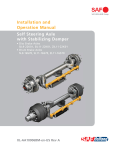
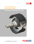
Service Manual for Drum Brake Axles Tapered and Parallel Spindle Axles XL-TA10006OM-en-US Rev C Contents Contents Page Contents Page Introduction ......................................................................... 3 Warranty .............................................................................. 3 Notes, Cautions, and Warnings ............................................. 3 Section 1 – General Safety Instructions ................................ 4 Section 2 – Model Identification........................................... 5 Section 3 – Identification Tag ............................................... 5 Brake Components Parts List Prior to November 30, 2012 ..... 6 Brake Components Parts List After November 30, 2012......... 7 Section 4 – Hubs, Bearings and Seal Removal ....................... 8 Section 5 – Bearing Inspection ........................................... 10 Section 6 – Hubs, Bearings and Seal Installation ................. 11 Section 7 – Hub Bearing Adjustment .................................. 13 Section 8 – Hub Cap Installation ........................................ 15 Section 9 – Filling Hub with Lubricant (Oil Based) .............. 15 Section 10 – Retracting the Brake Shoes or Slack Adjuster Control Arm(s).................................. 16 Section 11 – Brake Shoe Removal ...................................... 17 Section 12 – Brake Shoe Installation .................................. 19 Section 13 – Brake Adjuster Removal ................................. 22 Section 14 – Brake Adjuster Installation ............................. 22 Section 15 – S-Camshaft and Bearing Removal Procedure ... 23 Section 16 – S-Camshaft and Bearing Installation .............. 24 Section 17 – Brake Adjustment Procedure .......................... 26 Section 18 – ABS Sensor Replacement Procedure ............... 27 Section 19 – Axle Alignment Inspection .............................. 27 Section 20 – Routine Service Schedule ............................... 28 Section 21 – Torque and Lubrication Specifications ............. 29 Section 22 – Troubleshooting Chart .................................... 30 Introduction Notes, Cautions, and Warnings This manual provides the necessary information for the maintenance, inspection, and safe operation of the SAF® axle/brake system. Before starting any work on the unit, read and understand all the safety procedures presented in this manual. This manual contains the terms “NOTE”, “IMPORTANT”, “CAUTION”, and “WARNING” followed by important product information. These terms are defined as follows: Read this manual before using or servicing this product and keep it in a safe location for future reference. Updates to this manual, which are published as necessary, are available on the internet at www.safholland.us. Use only SAF-HOLLAND® Original Parts to service the SAF-HOLLAND INTEGRAL™ disc brake axle. A list of technical support locations that supply SAF-HOLLAND® Original Parts and an Aftermarket Parts Catalog are available on the internet at www.safholland.us or contact Customer Service at 888-396-6501. Warranty Refer to the complete warranty for the country in which the product will be used. A copy of the written warranty is included with the product or available on the internet at www.safholland.us. NOTE: Includes additional information to enable accurate and easy performance of procedures. IMPORTANT: Includes additional information that if not followed could lead to hindered product performance. Used without the safety alert symbol, indicates a potentially hazardous situation which, if not avoided, could result in property damage. Indicates a potentially hazardous situation which, if not avoided, could result in minor or moderate injury. Indicates a potentially hazardous situation which, if not avoided, could result in death or serious injury. XL-TA10006OM-en-US Rev C · 2014-08-27 · Amendments and Errors Reserved · © SAF-HOLLAND, Inc., SAF-HOLLAND, HOLLAND, SAF, and logos are trademarks of SAF-HOLLAND S.A., SAF-HOLLAND GmbH, and SAF-HOLLAND, Inc. 3 General Safety, Maintenance and Inspection Instructions 1. Safety Instructions General and Servicing Safety Instructions Operational and Road Safety Instructions Read and observe all Warning and Caution hazard alert messages. The alerts provide information that can help prevent serious personal injury, damage to components, or both. Failure to follow the instructions and safety precautions in this manual could result in improper servicing or operation leading to component failure which, if not avoided, could result in death or serious injury. All installation should be performed by a properly trained technician using proper/special tools, and safe procedures. NOTE: In the United States, workshop safety requirements are defined by federal and/or state Occupational Safety and Health Act (OSHA). Equivalent laws could exist in other countries. This manual is written based on the assumption that OSHA or other applicable employee safety regulations are followed by the location where work is performed. IMPORTANT: The wheel contact surfaces MUST be clean, smooth and free from grease. Failure to keep wheel and hub contact surfaces clean and clear of foreign material could allow wheel/hub separations which, if not avoided, could result in death or serious injury. Properly support and secure the vehicle and axles from unexpected movement when servicing the unit. Failure to properly support the vehicle and axles prior to commencing work could create a crush hazard which, if not avoided, could result in death or serious injury. Failure to follow the original manufacturer’s instructions regarding spring brake or air pressure control could allow an uncontrolled release of energy which could result in death or serious injury. Make sure that the brakes are not overheated from continuous operation. The parking brake MUST NOT be immediately applied when the brakes are overheated. If the parking brake is immediately applied to the brakes when overheated, the brake drums or discs could be damaged by different stress fields during cooling. Observe the operating recommendation of the trailer manufacturer for off-road operation of the installed axles. IMPORTANT: The definition of OFF-ROAD means driving on non-asphalt/non-concrete routes, such as gravel roads, agricultural and forestry tracks, on construction sites and in gravel pits. If possible, unload the trailer before performing any service procedures. After re-positioning the brake chamber, brake adjuster and/or ABS system as instructed in this manual, ALWAYS consult the manufacturer’s manual for proper operation. IMPORTANT: Key components on each axle system including but not limited to suspension, brake adjuster, brake chambers, bearings, hubs, and drums require information supplied by the original manufacturer of the components to ensure proper and safe operation of the axle system. Only the wheel and tire sizes approved by the trailer builder can be used. Before operating the vehicle, ensure that the maximum permissible axle load is not exceeded and that the load is distributed equally and uniformly. Failure to minimize the use of brakes during overheating conditions could result in deterioration of brake efficiency which, if not avoided, could result in death or serious injury. IMPORTANT: Use only SAF-HOLLAND® Original Parts to service your SAF-HOLLAND® INTEGRAL™ disc brake axle. Failure to maintain the SAF-HOLLAND® INTEGRAL™ disc brake with SAF-HOLLAND® Original Parts can result in brake or wheel bearing failure which, if not avoided, could result in death or serious injury. The wheel contact surfaces between the wheel and hub MUST NOT receive additional paint. IMPORTANT: Off-road operation of axles beyond the approved application design could result in damage and impair suspension system performance. SAF® axles require routine service, inspection and maintenance to maintain optimum performance, operational and road safety, and to recognize natural wear and defects before they become serious. Please refer to the Service Manual for Drum Brake Axles XL-TA1000060M-en-US which can be found at www.safholland.us or contact our customer service group at 888-396-6501. Service both roadside and curbside of an axle. Worn parts should be replaced in sets. Key components on each axle’s braking system, such as friction material, rotors and drums will normally wear over time. 4 XL-TA10006OM-en-US Rev C · 2014-08-27 · Amendments and Errors Reserved · © SAF-HOLLAND, Inc., SAF-HOLLAND, HOLLAND, SAF, and logos are trademarks of SAF-HOLLAND S.A., SAF-HOLLAND GmbH, and SAF-HOLLAND, Inc. Model and Serial Number 2. Model Identification The Drum Brake Axle Serial Tag is located near the center of the axle tube (Figure 1). Figure 1 SERIAL NUMBER TAG LOCATED NEAR CENTER OF AXLE TUBE 3. Identification Tag The sample tag illustrated will help interpret the information on the SAF-HOLLAND USA Inc®. serial number tag. The model number, axle body part number, axle beam rating, and serial number are listed on the tag (Figure 2). Figure 2 Record the tag numbers below for future quick reference. Axle Body Part Number _________________________________ Model Number _______________________________________ Axle Beam Rating _____________________________________ Serial Number _______________________________________ XL-TA10006OM-en-US Rev C · 2014-08-27 · Amendments and Errors Reserved · © SAF-HOLLAND, Inc., SAF-HOLLAND, HOLLAND, SAF, and logos are trademarks of SAF-HOLLAND S.A., SAF-HOLLAND GmbH, and SAF-HOLLAND, Inc. 5 Brake Components Parts List – Prior to November 30, 2012 5 16 8 1 9 25 23 24 4 3 22 20 21 19 2 20 13 12 17 LH AND 18 RH (NOT SHOWN) AXLE BRACKET 6 10 LH AND 11 RH (NOT SHOWN) 14 7 12 15 14 9 8 5 TAPERED SPINDLE AXLE SHOWN BRAKE COMPONENTS ITEM BRAKE COMPONENTS DESCRIPTION QTY ITEM QTY 1 Axle Body Assembly 1 14 Return Spring Pin 4 2 Fitting, Lubrication 2 15 Spring, Return-Hub/Drum 2 3 Bushing, Anchor Pin 4 16 Spring, Anchor Pin 4 4 Pin, Anchor 4 17 Housing, S-Cam Bearing, Left-Hand Slotted 1 5 Brake Shoe Assembly 4 18 Housing, S-Cam Bearing, Right-Hand Slotted 1 6 Bearing Assembly, S-Cam-Spider inboard 2 19 Bearing Assembly S-Camshaft 2 7 Bearing Assembly, S-Cam-Spider Outboard 2 20 O-Ring, S-Camshaft Bearing Seal-Inboard 4 8 Retainer, Roller 4 21 Housing, S-Cam Bearing 2 9 Roller, Brake Shoe 4 22 Screw, Thread Rolling Tapping 8 10 S-Camshaft, Left-Hand 1 23 Washer, Shaft End 2 11 S-Camshaft, Right-Hand (not shown) 1 24 Washer, Shaft End 2 12 Washer, S-Cam Bearing-Outboard 4 25 Retaining Ring 2 13 Retainer Ring 2 NOTE: 6 DESCRIPTION Refer to Drum Brake Axle Parts Manual XL-TA10058PM-en-US for axle component and service kit part numbers. XL-TA10006OM-en-US Rev C · 2014-08-27 · Amendments and Errors Reserved · © SAF-HOLLAND, Inc., SAF-HOLLAND, HOLLAND, SAF, and logos are trademarks of SAF-HOLLAND S.A., SAF-HOLLAND GmbH, and SAF-HOLLAND, Inc. Brake Components Parts List – After November 30, 2012 1 5 16 8 4 9 3 21 22 2 23 22 20 19 7 AXLE BRACKET 6 7 10 LH AND 11 RH (NOT SHOWN) 13 12 17 LH (18 RH NOT SHOWN) 24 14 (POST NOVEMBER 2012) 15 (POST MARCH 2014) 9 8 5 TAPERED SPINDLE AXLE SHOWN BRAKE COMPONENTS ITEM DESCRIPTION BRAKE COMPONENTS QTY ITEM DESCRIPTION QTY 1 Axle Body Assembly 1 13 Retainer Ring 2 2 Fitting, Lubrication 2 14 Return Spring Pin 4 3 Bushing, Anchor Pin 4 15 Spring, Return-Hub/Drum 2 4 Pin, Anchor 4 16 Spring, Anchor Pin 4 5 Brake Shoe Assembly 4 17 Cam Bearing Kit - Left-Hand 1 6 Bushing, Cam Bearing 2 18 Cam Bearing Kit - Right-Hand (not shown) 1 7 Cam Seal, Spider 4 19 Nut, Lock 8 8 Retainer, Cam Roller 4 20 Bolt, Hex Head Cap 8 9 Roller, Brake Shoe 4 21 Washer, Shaft End 2 10 S-Camshaft, Left-Hand 1 22 Washer, Shaft End 4 11 S-Camshaft, Right-Hand (not shown) 1 23 Retaining Ring 2 12 Washer, S-Cam Bearing-Outboard 2 24 Guide PLate, Brake Roller Shoe 2 NOTE: Refer to Drum Brake Axle Parts Manual XL-TA10058PM-en-US for axle component and service kit part numbers. XL-TA10006OM-en-US Rev C · 2014-08-27 · Amendments and Errors Reserved · © SAF-HOLLAND, Inc., SAF-HOLLAND, HOLLAND, SAF, and logos are trademarks of SAF-HOLLAND S.A., SAF-HOLLAND GmbH, and SAF-HOLLAND, Inc. 7 Hubs, Bearings, and Seal Components 4. Hubs, Bearings and Seal Removal Figure 3 NOTE: Before starting any axle/brake service procedures, park the vehicle on a level surface. Block the wheels to prevent the vehicle from moving. Support the vehicle and axle(s) with safety stands. DO NOT work under a vehicle supported only by jacks. Jacks can slip or fall over. Serious personal injury and damage to components can result. Failure to properly support the vehicle and axles prior to commencing work could create a crush hazard which, if not avoided, could result in death or serious injury. 1. Release the trailer brakes and cage the spring brakes according to the spring brake manufacturer’s instructions. Remove the tire and wheel assembly to access the hub and drum. 2. Remove the drum from the hub using a support device such as a drum dolly (Figure 3). Figure 4 Failure to support weight during installation or removal of the brake drum could create a crush hazard which, if not avoided, could result in minor to moderate injury. NOTE: It is necessary to retract the brake shoes in accordance with the brake adjuster’s manufacturer manual to allow the brake drum to clear the brake shoes during brake drum removal. 3. HUB CAP GASKET HUB CAP BOLTS (6) Remove the hub cap and gasket by removing six (6) bolts (Figure 4). NOTE: Be prepared to collect lubrication fluid when removing the hub cap. 8 XL-TA10006OM-en-US Rev C · 2014-08-27 · Amendments and Errors Reserved · © SAF-HOLLAND, Inc., SAF-HOLLAND, HOLLAND, SAF, and logos are trademarks of SAF-HOLLAND S.A., SAF-HOLLAND GmbH, and SAF-HOLLAND, Inc. Hubs, Bearings, and Seal Components 4. Remove the set screws (Figure 5). 5. Remove the axle nut from the spindle using a wrench with the axle nut socket. If the unit is equipped with a Pro-Torq® spindle nut, remove the nut and skip Step 5 (Figure 6). 6. Release the axle washer and the inner axle nut from the spindle (Figure 6). 7. Remove the outer hub bearing from the spindle (Figure 6). NOTE: With the axle nut, washer, and inner nut removed, it is possible to access the outer bearing. Figure 5 OUTER HUB BEARING INNER AXLE NUT AXLE WASHER SET SCREWS AXLE NUT DO NOT hit steel parts with a steel hammer as parts could break, sending flying steel fragments in any direction creating a hazard which, if not avoided, could result in minor to moderate injury. 8. Grasp the hub assembly with both hands and pull the hub assembly off the axle spindle (Figure 7). 3-PIECE SPINDLE NUT SHOWN Figure 6 NOTE: Depending on the type of hub seal, the hub seal and inner bearing could remain on spindle or come off with hub assembly. PRO-TORQ® SPINDLE NUT AXLE NUT SOCKET Figure 7 HUB ASSEMBLY XL-TA10006OM-en-US Rev C · 2014-08-27 · Amendments and Errors Reserved · © SAF-HOLLAND, Inc., SAF-HOLLAND, HOLLAND, SAF, and logos are trademarks of SAF-HOLLAND S.A., SAF-HOLLAND GmbH, and SAF-HOLLAND, Inc. 9 Hubs, Bearings, and Seal Components 9. Remove the inner hub bearing from the spindle or from the inside of the hub (Figure 8). 10. Remove the hub seal from the hub bore using a pry bar. A spindle mount hub seal can be driven off the spindle by striking the ring from the back side or prying off with a crow’s foot bar. Discard the used hub seal and use a new hub seal during re-assembly being careful not to gouge the spindle shoulder (Figure 8). DO NOT use a chisel to cut the seal. The shoulder can be damaged, resulting in a leak which could lead to wheel end and/or brake failure. Figure 8 HUB SEAL INNER HUB BEARING 5. Bearing Inspection Thoroughly clean the bearings. DO NOT mix a synthetic base grease or oil with an organic/mineral base lubricant. DO NOT spin dry the hub bearings with compressed air. Bearing damage could result. 1. After removing the hub assembly, clean excess grease from the bearings. IMPORTANT: A bearing which has been removed from a vehicle should be cleaned with solvent. When cleaning DO NOT use steam or water which will cause the bearings to rust. IMPORTANT: Bearings that are rusted, flaked, pitted, or have damaged cages should be replaced. It is recommended to replace all questionable bearings and ALWAYS replace the cup and cone as a matched set. NEVER re-assemble a tapered roller bearing in a damaged or worn housing or on damaged or worn spindles. Housings or spindles should be replaced and NOT re-machined if the bearing journal is worn. 10 XL-TA10006OM-en-US Rev C · 2014-08-27 · Amendments and Errors Reserved · © SAF-HOLLAND, Inc., SAF-HOLLAND, HOLLAND, SAF, and logos are trademarks of SAF-HOLLAND S.A., SAF-HOLLAND GmbH, and SAF-HOLLAND, Inc. Hubs, Bearings, and Seal Components 6. Hubs, Bearings and Seal Installation 6.1 Spindle mounted Hub Seal Installation instructions (Refer to 6.2 for hub mounted Hub Seal instructions) 1. Before installing the hub seal on the axle spindle, inspect the machined spindle seal surface for nicks, scratches, burrs or marks. If needed, use crocus cloth or emery cloth to repair any damaged areas. 2. Clean the threads and the keyway thoroughly with a wire brush to avoid false bearing adjustments and to avoid introduction of contaminants into the lubricant cavity. 3. Thoroughly clean the spindle and spindle threads of rust, dirt, grease or any other contaminants that could damage the hub seal and cause it to leak. NEVER install a spindle mounted hub seal in the hub and then force it onto the axle spindle by tightening the axle nut. Damage to the seal will result. 4. The seal assembly should be placed on the spindle so the words “Oil Bearing Side” are exposed to the oil (Figure 9). 5. Drive the hub seal into place using the seal installation tool and hammer. Rotate the hub seal installation tool in 1/4-turn intervals with every hammer tap until the seal is properly seated with the metal face of the seal flush with the inner shoulder of the axle spindle (Figure 10). 6. Apply a thin coat of oil to the O.D. of the seal. 7. Prepare the hub. Remove the old lube and thoroughly clean the hub cavity and hub bore. Inspect the inner hub bore for roughness. If needed, use an emery cloth to remove any burrs or old bore sealant. Figure 9 AXLE SPINDLE INNER SHOULDER KEYWAY HUB SEAL Figure 10 XL-TA10006OM-en-US Rev C · 2014-08-27 · Amendments and Errors Reserved · © SAF-HOLLAND, Inc., SAF-HOLLAND, HOLLAND, SAF, and logos are trademarks of SAF-HOLLAND S.A., SAF-HOLLAND GmbH, and SAF-HOLLAND, Inc. HUB SEAL INSTALLATION TOOL 11 Hubs, Bearings, and Seal Components 8. Install the inner and outer bearing cups into hub (Figure 11). 9. Pre-lube the inner bearing with the lubricant that is being retained and place it into the hub. Figure 11 INNER BEARING Failure to lubricate the bearing correctly and maintain proper lubrication could result in bearing damage. NOTE: If using grease and not oil for hub lubrication, the inner and outer bearing, and the hub cavity MUST be pre-packed with grease before installation. Lubricate the wheel end components with grease specified in the lubrication table in Section 21. HUB OUTER BEARING CUP INNER BEARING CUP 10. Push the hub onto the spindle until it contacts the seal. Pre-lube the outer bearing with the lubricant that is being retained and place it into the hub. Support the hub against the spindle inner shoulder until the outer bearing and adjusting nut are installed. DO NOT ram the hub into the bearing shoulder, which, if not avoided, could damage the hub seal. Figure 12 INNER BEARING 6.2 Hub Mounted Hub Seal Installation Instructions 1. Remove all the burrs from the hub bore and the spindle. Thoroughly clean the hub cavity and spindle. 2. Place the hub on a smooth, hard surface in a horizontal position. Pre-lube the inner bearing with the lubricant that is being retained and place it into the hub bearing cup (Figure 12). HUB BEARING CUP HUB NOTE: When using grease, pre-pack the inner bearing before placement into the hub. 3. With the correct head on the hub seal installation tool, place the hub seal on the installation tool, so that the words “Lube Side” face the inner bearing. Place the tool (with the seal correctly mounted in the tool head) into the hub bore. Use a three to five pound hammer to drive against the end of the tool. Drive the seal into the bore until complete bottoming is assured (Figure 13). Remove the Installation Tool and apply a thin layer of lubricant on the I.D. surface of the seal. Ensure the inner bearing rotates freely. Install a new seal if the seal is crooked or damaged or after installation. Figure 13 HUB SEAL INSTALLATION TOOL NOTE: DO NOT apply lubricant to the O.D. of the seal. 12 XL-TA10006OM-en-US Rev C · 2014-08-27 · Amendments and Errors Reserved · © SAF-HOLLAND, Inc., SAF-HOLLAND, HOLLAND, SAF, and logos are trademarks of SAF-HOLLAND S.A., SAF-HOLLAND GmbH, and SAF-HOLLAND, Inc. Hubs, Bearings, and Seal Components 4. 5. Align the hub bore to the center of spindle with mechanical supports. Gently push the hub assembly onto the spindle until the seal is seated against the bearing shoulder. Rotate the hub and lightly strike to ensure that the seal is properly seated against the bearing shoulder. Pre-lube the outer bearing with the lubricant that is being retained and place into the hub. Figure 14 PRE-PACK HUB CAVITY WITH GREASE PRE-PACK OUTER BEARING WITH GREASE NOTE: When using grease, pre-pack the hub cavity. The grease fill amount should be to a three (3) o’clock and nine (9) o’clock level. This is to ensure a 50% hub cavity fill. Use a template to hold the grease in place while filling the hub cavity (Figure 14). GREASE LEVEL TEMPLATE 7. Hub Bearing Adjustment 7.1 Hub Bearing Adjustment Using 3-Piece Axle Nut 1. Install the bearing inner-axle adjustment nut finger tight against the outer bearing (Figure 15). 2. While rotating the hub assembly, tighten the inner axle BEKVTUNFOUOVUUPGUMCT/tN 3. Back off the inner axle adjustment nut one full turn BOEUIFOSFUPSRVFUIFOVUUPGUMCT/tN XIJMF rotating the hub assembly. 4. Back off the inner axle nut approximately 1/4 turn and install the axle lock washer (Figure 16). DO NOT include socket backlash in the 1/4 turn. 5. Install the lock washer. If the hole in the washer is NOT aligned with the pin on the inner nut, turn the washer around and re-install. If the pin and hole are still NOT aligned, slightly adjust parts as needed. 6. Install the outer axle nut finger tight against the axle lock washer (Figure 16). Figure 15 OUTER BEARING INNER AXLE NUT 5JHIUFOUIFPVUFSBYMFOVUUPGUMCT/tN Figure 16 AXLE LOCK WASHER OUTER AXLE NUT XL-TA10006OM-en-US Rev C · 2014-08-27 · Amendments and Errors Reserved · © SAF-HOLLAND, Inc., SAF-HOLLAND, HOLLAND, SAF, and logos are trademarks of SAF-HOLLAND S.A., SAF-HOLLAND GmbH, and SAF-HOLLAND, Inc. 13 Hubs, Bearings, and Seal Components 8. Check the wheel bearing end play as follows: a. Attach the magnetic base of a dial indicator to the spindle. Touch the dial indicator stem to the hubcap gasket face (Figure 17). b. Reading Number One – Slightly rotate the wheel-end in both directions while pushing inward until the dial indicator does not change. Set the dial indicator to zero (Figure 17). Figure 17 HUB ASSEMBLY DIAL INDICATOR c. Reading Number Two − Slightly rotate the hub in both directions while pulling outward until the dial indicator does not change (Figure 17). d. End play is the difference between reading number one and reading number two. IMPORTANT: Final adjustment should allow the wheel to rotate freely with 0.001" to 0.005" (0.025 mm to 0.0127 mm) end play. If the end play is NOT within specification, readjustment is required. Figure 18 Failure to maintain proper hub bearing adjustment could allow bearing failure and wheel-end separation which, if not avoided, could result in death or serious injury. NOTE: If the wheel bearing end play needs adjustment, remove the outer nut and the lock washer. Tighten or loosen the inner nut as needed. Return to Step 6. 9. PRO-TORQ® SPINDLE NUT Install the set screw into an accessible threaded hole in the lock washer. Set screw MUST contact the inner BEKVTUJOHOVU5JHIUFOUPJOMCT/tN (Figure 19). 7.2. Hub Bearing Adjustment Using Pro-Torq® Axle Nut The unit could be equipped with a Pro-Torq® spindle nut (Figure 18). Refer to Stemco® “Pro-Torq® Installation Instructions” (Part No. 09-571-006) which can be found at www.stemco.com for more information. Figure 19 OUTER HUB BEARING INNER AXLE NUT AXLE WASHER SET SCREWS AXLE NUT 3-PIECE SPINDLE NUT SHOWN 14 XL-TA10006OM-en-US Rev C · 2014-08-27 · Amendments and Errors Reserved · © SAF-HOLLAND, Inc., SAF-HOLLAND, HOLLAND, SAF, and logos are trademarks of SAF-HOLLAND S.A., SAF-HOLLAND GmbH, and SAF-HOLLAND, Inc. Hubs Cap Installation 8. Hub Cap Installation 1. Figure 20 Install the hub cap assembly, making sure the hub cap gasket is in place (Figure 20). When installing the hub cap, make sure the hub cap gasket is not bent or damaged. HUB CAP GASKET HUB CAP DO NOT over torque. This can crush the hub cap gasket and cause a leak. 2. BOLTS (6) Install the six (6) bolts to secure the hub cap assembly (Figure 18).5JHIUFOUIFCPMUTUPGUMCT/tN 9. Filling Hub With Lubricant (Oil Based) IMPORTANT: DO NOT mix oil lubricant with grease lubricant. If the bearing assembly has been lubricated with grease DO NOT add oil. 3. Insert the plug into the hole in the hub cap (Figure 22). EL Allow the oil to flow through the bearings and level off. FULL ADD IMPORTANT: Axles equipped with a centralized tire inflation system MUST use a vented hub cap. EV 2. LE OIL Remove the plug and fill the hub to the FULL mark with the specified lubricant (oil), through the hole in the hub cap (Figure 21). VE L 1. Figure 21 FULL ADD Failure to correctly lubricate the bearings could damage the bearings which, if not avoided, could result in death or serious injury. OIL L OIL FILL LEVEL Figure 22 HUB CAP PLUG XL-TA10006OM-en-US Rev C · 2014-08-27 · Amendments and Errors Reserved · © SAF-HOLLAND, Inc., SAF-HOLLAND, HOLLAND, SAF, and logos are trademarks of SAF-HOLLAND S.A., SAF-HOLLAND GmbH, and SAF-HOLLAND, Inc. 15 Retracting Brake Shoes or Brake adjuster Arm 4. Re-install the drum on the hub using a support device such as a drum dolly jack (Figure 23). Figure 23 Failure to support weight during installation or removal of the brake drum could create a crush hazard which, if not avoided, could result in minor to moderate injury. Failure to uncage the spring brakes in accordance with manufacturer’s instructions after servicing is complete will prohibit proper brake function, which, could result in uneven brake system component wear. 10. Retracting the Brake Shoes or Brake Adjuster Control Arm(s) IMPORTANT: Refer to the brake adjuster’s manufacturer’s procedures for proper adjustment of the brake adjusters. Failure to operate with proper brake adjuster position could render brakes inoperable which, if not avoided, could result in death or serious injury. NOTE: When servicing the brakes, in some instances it could be necessary to fully retract the brake shoes in order to remove the brake drum. NOTE: When removing the S-Camshaft, it is necessary to retract the brake adjuster control arm(s) from the clevis so the brake adjuster can be removed from the S-Cam shaft. In both of the notes above, the brake shoes or the brake adjuster control arm(s) are retracted by turning the adjusting nut manually on the automatic brake adjuster. 16 XL-TA10006OM-en-US Rev C · 2014-08-27 · Amendments and Errors Reserved · © SAF-HOLLAND, Inc., SAF-HOLLAND, HOLLAND, SAF, and logos are trademarks of SAF-HOLLAND S.A., SAF-HOLLAND GmbH, and SAF-HOLLAND, Inc. Brake Shoe Replacement 11. Brake Shoe Removal Figure 24 NOTE: Before starting any axle/brake service procedures, park the vehicle on a level surface. Block the wheels to prevent the vehicle from moving. Support the vehicle and axle(s) with safety stands. DO NOT work under a vehicle supported only by jacks. Jacks can slip or fall over. Serious personal injury and damage to components can result. Failure to properly support the vehicle and axles prior to commencing work could create a crush hazard which, if not avoided, could result in death or serious injury. 1. Release the trailer brakes and cage the spring brakes according to the spring brake manufacturer’s instructions. Remove the tire and wheel assembly to access the hub and drum. 2. Remove the drum from the hub using a support device such as a drum dolly (Figure 24). Figure 25 Failure to support weight during installation or removal of brake drum could create a crush hazard which, if not avoided, could result in minor to moderate injury. NOTE: It is necessary to retract the brake shoes in accordance with the brake adjuster’s manufacturer’s manual to allow the brake drum to clear the brake shoes during the brake drum removal. 3. Using the brake spring pliers, unhook both the brake retaining springs from the brake shoes (Figure 25). 4. Press down on the lower brake shoe to disengage it from the anchor pin. Move the lower shoe to the side of the anchor bracket and lift the upper and lower shoes (still connected by brake return spring) from the anchor pins (Figure 26). IMPORTANT: The brake return spring, brake shoe rollers and roller retaining clips will remain on the brake shoes during this procedure. RETAINING SPRING BRAKE SPRING PLIERS Figure 26 UPPER BRAKE SHOE ANCHOR PINS LOWER BRAKE SHOE XL-TA10006OM-en-US Rev C · 2014-08-27 · Amendments and Errors Reserved · © SAF-HOLLAND, Inc., SAF-HOLLAND, HOLLAND, SAF, and logos are trademarks of SAF-HOLLAND S.A., SAF-HOLLAND GmbH, and SAF-HOLLAND, Inc. 17 Brake Shoe Replacement 5. Discard the used brake hardware. Figure 27 IMPORTANT: Brake hardware such as brake rollers, roller retaining clips and brake return springs experience fatigue during their normal lifespan and could not have the same performance characteristics as new components. Since most of these brake components are supplied new with the brake overhaul kit, the existing components should NOT be re-used. 6. DIAL INDICATOR With the brake shoes off, inspect the S-Camshaft and S-Camshaft bushings for wear. Verify that the S-Cam-tobushing radial free play is within specification by using a dial indicator and moving the S-Camshaft back and forth (Figure 27). Rotate the S-Camshaft in all directions when checking for radial free play. NOTE: Use a dial indicator to verify that S-Cam-to-bushing free play is 0.030" (0.76 mm) or less. 7. S-CAMSHAFT If radial free play is less than 0.030" (0.76 mm): DO NOT replace the bushings and the seals. If radial free play is more than 0.030" (0.76 mm): Replace the bushings and the seals. Inspect the brake shoes and components for wear: Figure 28 WEAR LIMIT 1/4" (6 mm) MINIMUM a. Inspect the spider for expanded anchor pin holes and for cracks. Brake spiders cannot be repaired and MUST be replaced with new axle assembly. b. Inspect the S-Camshaft bracket for broken welds, cracks and correct alignment. Replace the damaged brackets. c. Inspect the anchor pins for corrosion and wear. Replace worn or damaged anchor pins. ANCHOR PIN END S-CAM END NOTE: Follow the brake shoe manufacturer specifications for minimum brake shoe thickness and maximum brake drum inner diameter. A general guideline for replacing brake shoes is when the lining thickness is 1/4" (6 mm) or less, or when the lining rivets have begun to contact the drum (Figure 28). Failure to replace the brake shoes that are excessively worn could result in damage to brake drum or other components. d. Inspect the brake shoes for wear, expanded rivet holes, broken welds and correct alignment. Replace the shoes as a set with any of the above conditions. 18 XL-TA10006OM-en-US Rev C · 2014-08-27 · Amendments and Errors Reserved · © SAF-HOLLAND, Inc., SAF-HOLLAND, HOLLAND, SAF, and logos are trademarks of SAF-HOLLAND S.A., SAF-HOLLAND GmbH, and SAF-HOLLAND, Inc. Brake Shoe Replacement 8. Inspect the brake drums for wear. Figure 29 DO NOT operate the vehicle with the brake drum worn or machined beyond the discard dimension indicated by the drum manufacturer. The brake system may not operate correctly. Damage to components, death or serious injury, could result. Replace the brake drum if it is out-of-round. DO NOT turn or re-bore a brake drum beyond manufacturers recommendations. Doing so could decrease the strength and capacity of the drum which, if not avoided, could result in brake component damage. MEASURE INNER DRUM DIAMETER TO DETERMINE WEAR AND OUT OF ROUND IN ACCORDANCE WITH BRAKE DRUM MANUFACTER’S MANUAL. a. Inspect the brake drums for cracks, severe heat checking, heat spotting, scoring, pitting and distortion. Replace the drums as required. b. Measure the inside diameter of the drum in several locations with a drum caliper or internal micrometer (Figure 29). Figure 30 BRAKE SHOE ROLLER c. If brake drum is excessively worn or out of round replace the brake drum. RIBS Failure to replace an out of round brake drum could result in damage to the brake drum or other components. 12. Brake Shoe Installation 1. Install the brake shoe roller into the roller retainer (Figure 30). 2. Install the roller and roller retainer into the brake shoe ribs (Figure 30). 3. Coat anchor pins (ends only) completely with lubricant (Never-Seez®) and install (if removed) in the brake spider (Figure 31). ROLLER RETAINER Figure 31 ANCHOR PINS XL-TA10006OM-en-US Rev C · 2014-08-27 · Amendments and Errors Reserved · © SAF-HOLLAND, Inc., SAF-HOLLAND, HOLLAND, SAF, and logos are trademarks of SAF-HOLLAND S.A., SAF-HOLLAND GmbH, and SAF-HOLLAND, Inc. 19 Brake Shoe Replacement 4. Install the return spring pin into the brake shoe ribs (Figure 32). 5. Connect the hub/drum return spring to the upper and lower brake shoes (Figure 33). 6. Position the roller of the upper brake shoe up against the S-Cam, then place the other end of the shoe against the anchor pin (Figure 34). Failure to control spring pressure during the brake shoe installation could create a pinch hazard which, if not avoided, could result in minor to moderate injury. Figure 32 RETURN SPRING PIN Figure 33 HUB/DRUM RETURN SPRING Figure 34 UPPER BRAKE SHOE S-CAM ANCHOR PINS LOWER BRAKE SHOE 20 XL-TA10006OM-en-US Rev C · 2014-08-27 · Amendments and Errors Reserved · © SAF-HOLLAND, Inc., SAF-HOLLAND, HOLLAND, SAF, and logos are trademarks of SAF-HOLLAND S.A., SAF-HOLLAND GmbH, and SAF-HOLLAND, Inc. Brake Shoe Replacement 7. Position the roller of the lower brake shoe up against the S-Cam, then place the other end of the shoe against the anchor pin (Figure 35). 8. Install the two (2) brake anchor pin springs using the anchor pin pliers (Figure 36). 9. Make sure the brake linings are clean. 10. Re-install the drum using a support device such as a drum dolly jack (Figure 37). Failure to support weight during the installation or removal of the brake drum could create a crush hazard which, if not avoided, could result in minor to moderate injury. Figure 35 UPPER BRAKE SHOE S-CAM ANCHOR PINS LOWER BRAKE SHOE 11. Adjust the brakes as described in Section 17. Figure 36 SPRING PLIERS BRAKE ANCHOR PIN SPRING Figure 37 XL-TA10006OM-en-US Rev C · 2014-08-27 · Amendments and Errors Reserved · © SAF-HOLLAND, Inc., SAF-HOLLAND, HOLLAND, SAF, and logos are trademarks of SAF-HOLLAND S.A., SAF-HOLLAND GmbH, and SAF-HOLLAND, Inc. 21 Brake Adjuster Replacement 13. Brake Adjuster Removal Figure 38 NOTE: Maintenance procedures in this section require re-positioning of the brake adjuster. Consult the manufacturer’s manual for procedures to properly operate the brake adjusters. 1. Remove the cotter pins that secure the brake adjuster/brake chamber clevis pins (Figure 38). Remove the clevis pins. 2. Remove the retaining ring and washer that secure the brake adjuster to the S-Camshaft (Figure 39). 3. Remove the self-adjusting brake adjuster from the spline end of the brake S-Camshaft. 4. Rotate the adjusting mechanism to back the brake adjuster out of the clevis in accordance with the brake adjusters manual. BRAKE ADJUSTER CLEVIS PINS COTTER PINS 14. Brake Adjuster Installation 1. Apply an even coat of anti-seize compound to splined surface of the S-Camshaft. 2. Position the spacing washers on both sides of the brake adjuster, then install the brake adjuster onto the S-Camshaft spline and secure the brake adjuster on the S-Camshaft by assembling the retaining ring (Figure 40). 3. Align the brake adjuster to the clevis and pin together using the clevis pins and the cotter pins (Figure 38). 4. Apply service and the spring brake several times. Final brake adjustment is required to ensure proper initial brake operation. The brake adjuster will then seek the proper working stroke during normal operating conditions. Refer to the brake adjuster and brake chamber manufacturers' procedures for proper adjustment. Figure 39 SPACING WASHERS RETAINING RING S-CAM SPLINE CLEVIS PINS CLEVIS BRAKE ADJUSTER COTTER PINS Figure 40 BRAKE CHAMBER BRAKE ADJUSTMENT NUT CLEVIS PUSH ROD 22 JAM NUT XL-TA10006OM-en-US Rev C · 2014-08-27 · Amendments and Errors Reserved · © SAF-HOLLAND, Inc., SAF-HOLLAND, HOLLAND, SAF, and logos are trademarks of SAF-HOLLAND S.A., SAF-HOLLAND GmbH, and SAF-HOLLAND, Inc. S-camshaft Replacement 15. S-Camshaft and Bearing Removal Procedure 1. Figure 41 BRAKE SPIDER Remove the brake shoes and the brake adjuster as described in Section 11 and 13, respectively. 2. Remove the retaining ring from the spider end of the S-Camshaft (Figures 41). 3. Remove the S-Camshaft by sliding it out of the S-Camshaft bearing housing and bearings. It could be necessary to tap the end of the shaft with a soft mallet to release it from the bearings (Figure 41). 4. Remove the existing bolts securing the S-Camshaft bearing housing to the axle bracket (Figure 42). 5. Inspect the bearings assembly for wear and deterioration. Replace as necessary. AXLE BRACKET RETAINING RING S-CAMSHAFT Figure 42 S-CAMSHAFT BEARING HOUSING AXLE BRACKET BOLTS (4) XL-TA10006OM-en-US Rev C · 2014-08-27 · Amendments and Errors Reserved · © SAF-HOLLAND, Inc., SAF-HOLLAND, HOLLAND, SAF, and logos are trademarks of SAF-HOLLAND S.A., SAF-HOLLAND GmbH, and SAF-HOLLAND, Inc. 23 S-camshaft Replacement 16. S-Camshaft and Bearing Installation 1. Attach the S-Cam bearing housing bracket to the axle bracket, securing it with the four (4) nuts and bolts (Figure 43). 5JHIUFOUIFOVUTUPGUMCT/tN 2. Install the S-Camshaft bearing into the brake spider, ensuring that the bearing is centered (Figure 44). 3. Install the guide plate, and cam seals on the S-Camshaft and slide the S-Camshaft and the washer assembly through the S-Camshaft bearing in the brake spider (Figure 44). Figure 43 S-CAMSHAFT BEARING HOUSING AXLE BRACKET BOLTS (4) SPIDER GREASE FITTING NOTE: Cam seals, refer to Figure 44, MUST be installed with the metal shoulder oriented toward the wheel, and the open end oriented toward the center of the vehicle. This facilitates complete lubrication of the s-cam bearing while allowing air to purge from the s-cam bearing away from the brake shoes. Failure to center S-Camshaft bearing into the brake spider, and to properly orient cam seals, may not allow grease flow to bearing which, if not avoided, could result in premature bearing failure (Figure 45). NUTS (4) Figure 44 S-CAM BEARING CAM SEAL GUIDE PLATE, BRAKE ROLLER SHOE S-CAMSHAFT Figure 45 SPIDER GREASE SEAL LIPS INBOARD SIDE OF AXLE SPIDER GREASE SEAL LIPS 24 XL-TA10006OM-en-US Rev C · 2014-08-27 · Amendments and Errors Reserved · © SAF-HOLLAND, Inc., SAF-HOLLAND, HOLLAND, SAF, and logos are trademarks of SAF-HOLLAND S.A., SAF-HOLLAND GmbH, and SAF-HOLLAND, Inc. S-camshaft Replacement 5. Install the cam seal washer and the retaining ring onto the S-Camshaft and slide the S-Camshaft into the S-Camshaft bearing housing bracket (Figure 46). 6. Install the brake shoes and the brake adjusters as described in Section 12 and 14, respectively. 7. Inspect the S-Camshaft installation to ensure that the correct S-Camshaft has been installed on the required side of the axle for proper operation (Figure 47). Figure 46 HOUSING BRACKET S-CAM BEARING RETAINING RING WASHER CAM SEAL BRAKE SPIDER GUIDE PLATE, BRAKE ROLLER SHOE S-CAMSHAFT Figure 47 CORRECT S-CAMSHAFT INSTALLED WHEEL ROTATION S-CAM ROTATION INCORRECT S-CAMSHAFT INSTALLED WHEEL ROTATION S-CAM ROTATION XL-TA10006OM-en-US Rev C · 2014-08-27 · Amendments and Errors Reserved · © SAF-HOLLAND, Inc., SAF-HOLLAND, HOLLAND, SAF, and logos are trademarks of SAF-HOLLAND S.A., SAF-HOLLAND GmbH, and SAF-HOLLAND, Inc. 25 Brake Adjustment 8. Lubricate the S-Camshaft bearings with grease specified in the Lubrication Table in Section 21 (Figure 48). Figure 48 17. Brake Adjustment Procedure 1. Verify that the spring brakes are caged prior to beginning the adjustment procedure. 2. Adjust the brake adjuster until the brake lining contacts the brake drum, then back off 1/2 turn. 3. Apply the service brakes using normal operating pressure (average line pressure should be 90 psi, but not less than 80 psi). Check the following while brake pressure is applied. 4. The optimum distance of the push rod travel should be approximately 1.5"-1.75" (38-44 mm) (Figure 49). Angle between the push rod and the brake adjuster with the brake applied, should be 95°-100° (Figure 50). Brake lining to drum contact. A 0.010" feeler gauge should not fit between the lining and the drum contact area. S-CAMSHAFT LUBRICATION FITTING LOCATIONS BRAKE ADJUSTER S-CAMSHAFT S-CAM BEARING HOUSING Figure 49 Release the air pressure from the service brake system and check to see that all brakes release to the normal relaxed position. If all the brakes do not properly release, Refer to Troubleshooting Chart in Section 22. Failure to adjust the brakes in accordance with manufacturer’s instructions prior to placing the trailer back in service will prohibit proper brake function which, if not avoided, could result in uneven brake system component wear. 5. Uncage the spring brakes. Failure to uncage the spring brakes in accordance with manufacturers's instructions after servicing is complete will prohibit proper brake function which, if not avoided, could result in death or serious injury. OPTIMUM PUSH ROD TRAVEL APPROX. 1.75"-2.0" (38-44 mm) Figure 50 95-100O 95-100O (WITH BRAKES APPLIED) 26 XL-TA10006OM-en-US Rev C · 2014-08-27 · Amendments and Errors Reserved · © SAF-HOLLAND, Inc., SAF-HOLLAND, HOLLAND, SAF, and logos are trademarks of SAF-HOLLAND S.A., SAF-HOLLAND GmbH, and SAF-HOLLAND, Inc. ABS Sensor Replacement 18. ABS Sensor Replacement Procedure Figure 51 18.1 Sensor Removal ABS SENSOR CONNECTOR NOTE: ABS sensors MUST match the system. DO NOT mix sensors from different manufacturers. 1. Manually release the brakes. 2. Remove the brake drum assembly as described in Section 4. 3. Disconnect the ABS sensor connector and remove the sensor from the sensor holder by pulling straight out (Figure 51). 4. Remove the sensor retaining spring clip, if necessary. ABS SENSOR HOLDER 18.2 Sensor Installation NOTE: Be sure to use the correct spring clip for the sensor being installed. 1. Install the sensor retaining spring clip, if removed, into the sensor holder. 2. Install the ABS sensor into the spring clip and the sensor holder. Push the sensor in until it contacts the tone ring (Figure 52). 3. Connect the ABS sensor connector. 4. Re-install the drum using support device such as a drum dolly jack (Figure 37). 5. Adjust the brakes as described in Section 17. Figure 52 SPRING CLIP ABS SENSOR HOLDER ABS SENSOR CONNECTOR 19. Axle Alignment Inspection NOTE: Alignment can be achieved using an optical device designed specifically for this purpose. Follow the instructions in the optical device operating instructions to align the axles. 1. To manually align the axles attached to the trailer, first pull the trailer in a straight line for a sufficient distance to release/clear any binds in the suspension. Figure 53 NOTE: A straight, unbound suspension is the position of a suspension during normal operations. Using the alignment procedures per the suspension manufactuer’s recommendations, align the axles to the following specifications. 2. 3. Measure the distance from the king pin to the centerline of the spindles on each side of the front axle. Dimensions A and B MUST be equal to within 1/8" (4 mm) (Figure 53, A and B). A=B C=D C A KING PIN B D Measure the distance from the centerline of the spindles of the front axle to the centerline of the spindles of each additional axle. Dimension C and D MUST be equal to within 1/16" (1 mm) (Figure 53, C and D). XL-TA10006OM-en-US Rev C · 2014-08-27 · Amendments and Errors Reserved · © SAF-HOLLAND, Inc., SAF-HOLLAND, HOLLAND, SAF, and logos are trademarks of SAF-HOLLAND S.A., SAF-HOLLAND GmbH, and SAF-HOLLAND, Inc. 27 Routine Service Schedule 20. Routine Service Schedule WHICHEVER OCCURS FIRST PERIODIC CHECKS MILEAGE INTERVALS AFTER FIRST 3,000 MILES EVERY 10,000 MILES EVERY 50,000 MILES EVERY 100,000 MILES TIME INTERVALS AFTER FIRST MONTH EVERY MONTH EVERY 6 MONTHS EVERY 12 MONTHS Check brake linings for wear. t t Check S-Camshaft for proper operation. t t Check brake adjusters for correct function. t t Check air brake system for leaks (brake applied). t t Check axle structural components for cracks or damage. t t Check hub lubrication level for excessive leakage. t t VISUAL INSPECTION FOR WEAR/DAMAGE MECHANICAL CHECK Attention: Torque check wheel nuts after the first 5-100 miles (8-160 km) from date vehicle was placed into service and after every wheel removal. Continually check wheel torque every 10,000 miles (16,000 km), or at the intervals indicated in your vehicle owner's manual, whichever occurs first. t Torque check all nuts and bolts to recommended setting. t t Check and adjust wheel bearing end play. t t Pack hub bearings with fresh lubricant (also after every brake lining replacement, check hub bearing wear). Lubricate S-Camshaft bearing bushings. t t t t t SAFETY INSPECTION Check brake lining to drum clearance for correct adjustment – re-adjust clearance if necessary. Check service brake and parking brake for performance. SPECIAL SERVICE CONDITIONS Vehicles with long standing periods. Service at specified time intervals, e.g. trailer used for storage or frequently left standing for several days at a time. Vehicles used under extreme conditions. Service at suitably reduced intervals, e.g. trailer operating in continuous multi-shifts or in off-road construction sites. Warranty claims will only be accepted as long as the operation and maintenance instructions have been complied with and if SAF-HOLLAND® approved spare parts have been fitted. 28 XL-TA10006OM-en-US Rev C · 2014-08-27 · Amendments and Errors Reserved · © SAF-HOLLAND, Inc., SAF-HOLLAND, HOLLAND, SAF, and logos are trademarks of SAF-HOLLAND S.A., SAF-HOLLAND GmbH, and SAF-HOLLAND, Inc. Torque and Lubrication 21. Torque and Lubrication Specifications TORQUE SPECIFICATIONS LUBRICATION SPECIFICATION COMPONENT TORQUE VALUE Grease Fitting, Spider JOMCT/tN COMPONENT SURFACE TO BE LUBRICATED TORQUE VALUE Refer to Section 7 S-Camshafts S-Camshaft Bearings (Four (4) Grease Fittings per Axle) Lithium Complex Grease Axle, Inner Nut Axle, Outer Nut GUMCT/tN S-Camshafts S-Camshaft Spline NeverSeez® Air Chamber Nuts GUMCT/tN Brakes Brake Shoe Rollers anchor Pins NeverSeez® Hubcap Bolts GUMCT/tN Self-Threading Screw GUMCT/tN Brakes − Brake Adjuster Brake Adjuster Grease Fitting Lithium Complex Grease Bearings and Hubs 80/90 Gear Oil or Lithium Complex Grease* Axle * Oil lubed bearings and hubs should remain lubricated with oil, grease lubed bearings and hubs should remain lubricated with grease. NOTE: Intervals are based upon normal operations. Reduce intervals to compensate for abnormal operations or severe conditions. During inactive periods, sufficient lubrication must be performed for equipment preservation. XL-TA10006OM-en-US Rev C · 2014-08-27 · Amendments and Errors Reserved · © SAF-HOLLAND, Inc., SAF-HOLLAND, HOLLAND, SAF, and logos are trademarks of SAF-HOLLAND S.A., SAF-HOLLAND GmbH, and SAF-HOLLAND, Inc. 29 Troubleshooting 22. Troubleshooting Chart PROBLEM Brakes will not release No brakes or insufficient brakes NOTE: All of the possible causes would result in brake lockup. Dog tracking Uneven tire wear Grabbing brakes Excessive heat cracks on drum Lubricate brake operating parts Brake hoses Restricted Replace hoses Brakes out of adjustment Adjust brakes Damaged brake assembly Replace or repair as required Source of air supply shut off at tractor Open cutout cocks at rear of tractor cab or push control valve “IN” Low brake line pressure Check air pressure gauge on tractor - inoperative Brake lines between tractor and trailer not properly coupled Properly couple brake lines Reservoir drain cock open Close drain cock Leaf spring broken Replace complete spring Bent Axle Replace or straighten axle Frame or suspension out of alignment Straighten frame or align axles Over or under inflation Inflate to proper pressure Loose wheel stud nuts or clamps Tighten wheel stud nuts or clamps Loose or tight wheel bearing adjustment Adjust bearings Axle bent or out of alignment Straighten, align or replace axle Tires not properly matched Match tires Improper acting brakes Correct brakes as required Rapid Stopping Apply brakes slowly when approaching stop High-speed driving on turns Reduce speed Oil, grease or foreign material on brake lining Reline brakes Brakes out of alignment Adjust brakes Brake drum out-of-round Replace brake drum Damaged brake chamber or internal assembly Replace brake chamber/internal assembly Leaky or broken hose between relay valve and brake chamber Replace or Repair as required Rapid stopping or poor air flow to brakes Replace drum Out of adjustment Adjust brakes Binding S-Cam, anchor pins or chamber rod end pin Lubricate and free up Damaged brake assembly/brake drum out-of-round Replace or repair as required ABS inoperable Slow brake application or release 30 RESOLUTION POSSIBLE CAUSE Brake shoes bound up at anchor pins Refer to ABS manufacturer’s service literature Lack of lubrication Lubricate brake operating parts Excessive travel in brake chamber push rod Adjust brakes Restiction in hose or lines Replace hoses Defective brake valve Replace brake valve XL-TA10006OM-en-US Rev C · 2014-08-27 · Amendments and Errors Reserved · © SAF-HOLLAND, Inc., SAF-HOLLAND, HOLLAND, SAF, and logos are trademarks of SAF-HOLLAND S.A., SAF-HOLLAND GmbH, and SAF-HOLLAND, Inc. Notes XL-TA10006OM-en-US Rev C · 2014-08-27 · Amendments and Errors Reserved · © SAF-HOLLAND, Inc., SAF-HOLLAND, HOLLAND, SAF, and logos are trademarks of SAF-HOLLAND S.A., SAF-HOLLAND GmbH, and SAF-HOLLAND, Inc. 31 SAF-HOLLAND Original Parts are the same quality components used in the original component assembly. SAF-HOLLAND Original Parts are tested and designed to provide maximum performance and durability. Will-fits, look-alikes or, worse yet, counterfeit parts will only limit the performance potential and could possibly void SAF-HOLLAND’s warranty. Always be sure to spec SAF-HOLLAND Original Parts when servicing your SAF-HOLLAND product. SAF-HOLLAND USA · 888.396.6501 · Fax 800.356.3929 www.safholland.us · · SAF-HOLLAND CANADA WESTERN CANADA 604.574.7491 · · Fax 604.574.0244 52.55.5362.8743 · Fax 52.55.5362.8743 519.537.3494 Fax 800.565.7753 www.safholland.ca SAF-HOLLAND MEXICO www.safholland.com.mx [email protected] SAF-HOLLAND USA, INC. 1950 Industrial Blvd., Muskegon, MI 49442 www.safholland.com · XL-TA10006OM-en-US Rev C · 2014-08-27 · Amendments and Errors Reserved · © SAF-HOLLAND, Inc., SAF-HOLLAND, HOLLAND, SAF, and logos are trademarks of SAF-HOLLAND S.A., SAF-HOLLAND GmbH, and SAF-HOLLAND, Inc. From fifth wheel rebuild kits to suspension bushing repair kits,