1
Comfortstar
Service manual for 13seer Heatpump Condensing
Filter
Expansion/check
Valve
Expansion /check
Valve
Service Valve
of Liquid Pipe
Axial Flow Fan
Filter
Liquid
separator
Outdoor
Heat
Exchanger
Service Valve
of Gas Pipe
Indoor
Heat Exchanger
Centrifugal Fan
4-Way Valve
Compressor
Cooling
Heating
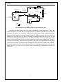
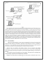
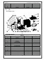
Fig.1 Working Principle Diagram of Heat Pump Condensing Unit
The working principle diagram of the heat pump Air Conditioner is shown above in fig.1. When the
system operates in cool mode, the low temperature and low pressure refrigerant gas from the heat
exchanger of the indoor unit is sucked by compressor and compressed, the high temperature and high
pressure gas is discharged into heat exchanger of outdoor unit, heating exchanges with air of outside and
turns into the refrigerant liquid, the liquid is throttled by throttling element and changed into the low
temperature and low pressure liquid then flows into the heat exchanger of indoor unit, heating exchange
with the air of the indoor then turns into the low temperature and low pressure refrigerant gas. The above
circle goes round and round. When the system operates in heat mode, the refrigerant flows in the reversible
cycle as the cool mode. The refrigerant gas discharges the heat volume in the indoor heat exchanger,
through the expansion valve and sucks the heating volume from outdoor heat exchanger and forms the heat
pump cycle, this cycle goes round and round, and the demanded high temperature environment is
maintained.
3