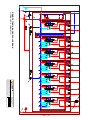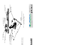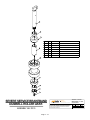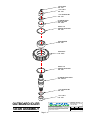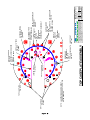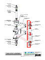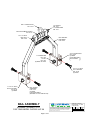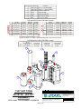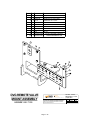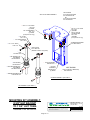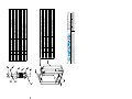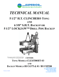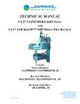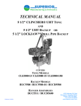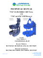
1
TECHNICAL MANUAL
7 5/8" CLINCHER® UHT TONG
AND
7 5/8" OR 8 5/8" UHT BACKUP
Photo represents
CLE7625UHT-02
with BUC8625-02
Illustration represents
CLE7625UHT-08
with BUC8625-02
COVERS
TONG MODEL’S
CLE7625UHT-02,-08, -09
BACKUP MODELS
BUC7625-02 / BUC8625-02, -05 & -06 / BUCT8625
HANGER ASSEMBLIES
BUC7600 / BUC7600-02 / BUC7600-04 / BUCF7625
Published: 10/2004
4225 Highway 90, East
Broussard, Louisiana 70518
Phone: (337) 837-8847
Fax: (337) 837-8839
www.superior-manf.com
TECHNICAL MANUAL
7 5/8" CLINCHER®UHT TONG
AND
7 5/8" OR 8 5/8" UHT BACKUP
COVERS
TONG MODEL’S
CLE7625UHT-02, -08, -09
BACKUP MODELS
BUC7625-02 / BUC8625-02, -05 & -06 / BUCT8625
HANGER ASSEMBLIES
BUC7600 / BUC7600-02 / BUC7600-04 / BUCF7625
Published: 10/2004
4225 Highway 90, East
Broussard, Louisiana 70518
Phone: (337) 837-8847
Fax: (337) 837-8839
www.superior-manf.com
©Copyright, 2004, SUPERIOR Manufacturing & Hydraulics, Inc. All rights reserved. This document is the
property of SUPERIOR Manufacturing & Hydraulics, Inc. It is supplied as reference information to users of
our products. This docum ent is considered confidential and is not to be disclosed, copied or reproduced,
transmitted, transcribed in any form or stored in any type of system without the express written consent of
SUPERIOR Manufacturing & Hydraulics, Inc.
CLINCHER®, CHROMEMASTER™, LOCKJAW™, HYTOPS™, Drillmaster, GRIT FACE™ &
Low-Friction are trademarks of SUPERIOR Manufacturing & Hydraulics, Inc.
The products described in this m anual are covered by U.S. and foreign Patent s and/or pending Patent
Applications.
This manual is not a controlled document and is subject to revision
without notice. To receive updates and insure you have access to
the latest information concerning the 7 5/8" CLINCHER® UHT
Tong and 7 5/8" or 8 5/8" UHT Backup, we request you complete
this form and return the lower half to SUPERIOR Manufacturing
and Hydraulics by mail or facsimile. Access to our manuals can
also be acquired through our web site www.superior-manf.com.
Select the tab ‘CLINCHER® Products’, select the equipment from
the list to get Specs page, select the tab ‘Download Manual’.
Name:
Company:
Address:
Address:
City:
Postal Code:
Telephone:
State:
Country:
Fax:
Tong Model No.:
Backup Model No.:
Assembly Date:
Serial No.:
Serial No.:
7 5/8" CLINCHER® UHT Tong and 7 5/8" or 8 5/8" UHT Backup
Technical Manual Registration Form
Name:
Return To:
Company:
SUPERIOR Mfg. & Hyd.
4225 Hwy. 90 East
Broussard, LA 70518
USA
Address:
Address:
City:
Postal Code:
Telephone:
Country:
Fax:
Tong Model No.:
Serial No.:
Backup Model No.:
Serial No.:
Assembly Date:
Telephone: 337-837-8847
Facsimile: 337-837-8839
Web Site: www.superior-manf.com
TABLE OF CONTENTS
Hazard Warnings
Description, Features, & Specifications
Jaws, Adapters, & Die Information
Assembly Torque Requirements
Operational Instructions
Maintenance Instructions & Trouble Shooting
Spare Parts Recommendations
Accessories and Options
UHT TONG Illustrations
UHT BACKUP & Mounting Kit Illustrations
Lift Cylinder Illustration
Load Cell and Torque Gauge
Motor Service Manuals
Valve Technical Data
1
2
3
4
5
6
7
8
9
10
11
12
13
14
7 5/8" CLINCHER® UHT TONG and 7 5/8" or 8 5/8" UHT BACKUP
REVISION TABLE
Section
Page
Date
SUPERIOR Manufacturing & Hydraulics, Inc.
7 5/8" CLINCHER® UHT Tong and 7 5/8" or 8 5/8" UHT Backup
Revision: 02/08
Page 0 - 1
Description
Page 0 - 2
DECLARATION OF CONFORMITY
Superior Manufacturing and Hydraulics Incorporated hereby declare that:
The 7 5/8" CLINCHER® Unit CLE7625UHT-02, complete with 8 5/8" Backup BUC8625-02 and
Hanger Assembly BUC7600-01 and as;
A hydraulically powered Tong and Backup unit provided for a means of making up, or breaking
out, high torque tubular connections to the following specification:
Maximum Torque
Maximum Operating Pressure
RPM @ 35 GPM / 132 LPM / Manual Gearbox
High
Low
Tong Handle Length
Backup Handle Length
Length
Width
Weight- Tong w/ Backup & Rigid Bail [approximate]
2 Tong Jaw Sizes Limited to 14,000 ft. lbs. / 30,000 ft. lbs.
1 Backup Jaw Size
30,000 ft. lbs. / 40,675 Nm
3,000 P.S.I. / 207 Bar
Max Recommended Flow Rate 65 GPM / 227 LPM*
42
7
36" / 91.4 cm
32" / 81.3 cm
56" / 142.2 cm
34" / 86.4 cm
3,100 lbs. / 1,406 Kg
2 3/8" thru 4 1/2" / 4 1/2" thru 7 5/8
2 3/8" thru 8.750"
*With optional A-35 valve 78 RPM High and 13 RPM Low
Is in accordance with;
The European Machinery Directive 98/37/EC being implemented in the United Kingdom by the
Supply of Machinery (Safety) Regulations 1992 and as amended by S.I. 1992/3073, S.I.
1994/2063 and S.I. 2005/831.
And the;
The European Directive on Equipment and Protective Systems Intended for Use in Potentially
Explosive Atmospheres 94/9/EC, being implemented in the United Kingdom by The Equipment
and Protective Systems Intended for Use in Potentially Explosive Atmospheres Regulations 1996
(SI 1996/192) and as amended by The Equipment and Protective Systems Intended for Use in
Potentially Explosive Atmospheres (Amendment) Regulations 2001 (SI 2001 No.3766).
SUPERIOR Manufacturing & Hydraulics, Inc.
7 5/8" CLINCHER® UHT Tong and 8 5/8" UHT Backup
Revision: 02/07
Page 00 - 1
DECLARATION OF CONFORMITY
This equipment has been retrospectively assessed and was found to be in accordance with the
following European Harmonized Standards:
BS EN ISO 12100 Part 1: Safety of Machinery. Basic concepts, general principles for design
BS EN ISO 12100 Part 2: Safety of Machinery. Technical principles
BS EN 13463 Part 1: Non-electrical Equipment Intended for Use in Potentially Explosive
Atmospheres - Basic Method and Requirements.
BS EN 13463 Part 5: Non-electrical equipment intended for use in potentially explosive
atmospheres - Protection by constructional safety c
BS EN 953 Safety of Machinery – Guards – General Requirements for the Design and
Construction of Fixed and Movable Guards
BS EN 982 Safety of Machinery – Safety Requirements for Fluid Power Systems and Their
Components - Hydraulics
BS EN 1050 Safety of Machinery – Principles for Risk Assessment
The American Institute of Steel Construction (AISC) Construction Code – 9th Edition DNV
Classification Note 30.2 – Fatigue Strength Analysis for Mobile Offshore Units
This equipment has been classified as suitable for use within a potentially explosive atmosphere
as follows.
I hereby declare that the 7 5/8" CLINCHER® Unit CLE7625UHT-02, complete with 8 5/8" Backup
BUC8625-02 and Hanger Assembly BUC7600-01 has been designed and manufactured to
comply with the relevant sections and essential health and safety requirements of the
aforementioned Standards, Codes and Directives / Regulations.
Gary Ebbrell
Technical Director
February 2007
Date
Note: InterSkill Global Limited, Suite 4 Badentoy Business Centre, Badentoy Crescent, Badentoy Industrial
Estate, Portlethen, Aberdeenshire acted as consultants to Superior Manufacturing and Hydraulics
Incorporated, 4225 Highway 90 East, Broussard, Louisiana, 70518, USA with specific regard to compliance
with European Directives for Machinery and Equipment and Protective Systems Intended for Use in
Potentially Explosive Atmospheres. InterSkill Global Limited are Superior Manufacturing and Hydraulics
Incorporated’s representatives within the EEA.
SUPERIOR Manufacturing & Hydraulics, Inc.
7 5/8" CLINCHER UHT Tong and 8 5/8" UHT Backup
Revision: 02/07
Page 00 - 2
DECLARATION OF CONFORMITY
McCoy Drilling & Completions hereby declares that:
The 7 5/8" CLINCHER® Casing Tong CLE7625UHT-09, complete with 8 5/8”CLINCHER®
Backup BUCT8625 and as;
A hydraulically powered Tong and Backup unit provided for a means of making up, or breaking
out, high torque tubular connections to the following specification:
Maximum Torque
Maximum Operating Pressure
RPM @ 35 GPM / 132 LPM / Manual Gearbox
High
Low
Tong Handle Length
Backup Handle Length
Length
Width
Height
Weight [approximate]
Tong Jaw Sizes Limited to 14,000 ft. lbs. / 30,000 ft. lbs.
Backup Jaw Size
30,000 ft. lbs. / 40,675 Nm
3,000 P.S.I. / 207 Bar
Max Recommended Flow Rate 65 GPM / 227 LPM
42
7
37 1/4" / 94.6 cm
32” / 81.3 cm
57.5" / 146 cm
39.5" / 100.3 cm
67.5" / 171.4 cm
3,200 lbs. / 1,451 Kg
2 3/8” thru 4 1/2” / 4 1/2" thru 7 5/8”
2 3/8” thru 8.750”
Is in accordance with;
The European Machinery Directive 98/37/EC and being implemented in the United Kingdom by the
Supply of Machinery (Safety) Regulations 1992 and as amended by S.I. 1992/3073, S.I.
1994/2063 and S.I. 2005/831.
And the;
The European Directive on Equipment and Protective Systems Intended for Use in Potentially
Explosive Atmospheres 94/9/EC, being implemented in the United Kingdom by The Equipment
and Protective Systems Intended for Use in Potentially Explosive Atmospheres Regulations 1996
(SI 1996/192) and as amended by The Equipment and Protective Systems Intended for Use in
Potentially Explosive Atmospheres (Amendment) Regulations 2001 (SI 2001 No.3766).
Page 00 - 1
DECLARATION OF CONFORMITY
This equipment has been retrospectively assessed and was found to be in accordance with the
following European Harmonized Standards:
BS EN ISO 12100 Part 1: Safety of Machinery. Basic concepts, general principles for design
BS EN ISO 12100 Part 2: Safety of Machinery. Technical principles
BS EN 13463 Part 1: Non-electrical Equipment Intended for Use in Potentially Explosive
Atmospheres - Basic Method and Requirements.
BS EN 13463 Part 5: Non-electrical equipment intended for use in potentially explosive
atmospheres - Protection by constructional safety c
BS EN 953 Safety of Machinery – Guards – General Requirements for the Design and
Construction of Fixed and Movable Guards
BS EN 982 Safety of Machinery – Safety Requirements for Fluid Power Systems and Their
Components - Hydraulics
BS EN 1050 Safety of Machinery – Principles for Risk Assessment
The American Institute of Steel Construction (AISC) Construction Code – 9th Edition DNV
Classification Note 30.2 – Fatigue Strength Analysis for Mobile Offshore Units
This equipment has been classified as suitable for use within a potentially explosive atmosphere
as follows.
I hereby declare that the 7 5/8" CLINCHER® Casing Tong CLE7625UHT-09, complete with
8 5/8”CLINCHER® Backup BUCT8625 has been designed and manufactured to comply with the
relevant sections and essential health and safety requirements of the aforementioned Standards,
Codes and Directives / Regulations.
Date
Page 00 - 2
7 5/8" CLINCHER® UHT Tong and Backup
HAZARD WARNING
Nomenclature used in this manual:
WARNING
concerns an operating procedure or practice that, if not strictly observed, can
result in injury to personnel or loss of life
Caution
concerns an operating procedure or practice that, if not strictly observed, can
result in damage to or destruction of equipment
Note
concerns an operating procedure or practice that needs highlighting
CLINCHER® UHT Tongs and Backups are manufactured to provide a means of making up or
breaking out high torque tubular connections. They utilize high pressure hydraulic fluid power
which can cause the tong to move suddenly and with great force if the tong is not properly rigged up
and operated. CLINCHER® Tongs and Backups contain rotating and reciprocating parts which can
severely or fatally injure personnel who are operating, repairing, or near this equipment during its
operation. WARNING: Tongs and Backups are not to be operated by untrained personnel or
personnel with diminished physical or mental capacity. No work of any type, including
changing of dies, is to be carried out while the tong and backup are connected to any hydraulic
power unit.
CLINCHER® UHT Tongs and Backups are heavy tools. They should be suspended from a secure,
high strength 7/8" IWRC minimum diameter wire cable with a 31 ton minimum breaking strength.
The wire rope should be hung as close to the center of the wellbore as possible, without interfering
with drilling equipment operation, to allow the tong to be readily swung into the working position.
Vertical position control should be achieved by means of a CLINCHER® hydraulically operated
lift cylinder/spring hanger. WARNING: Users must insure the entire suspension system
including cables, rig mounting points, lift cylinders, tong lifting brackets/bridles, winches,
pulleys, counter weights, etc., are capable of handling the static weight of the tong and backup
plus any loads which could be transferred to it during the makeup or breakout process PLUS
any shock loads which may be seen during operation. This system must readily allow
downward movement equal to a minimum of the thread makeup distance to avoid overloading
the suspension system and/or damage to equipment.
A 1" IWRC minimum diameter wire cable with a 51.7 ton minimum breaking strength or better,
should be attached at a 90 degree angle to the tong and at the same level to insure proper readout of
torque indicator. A SNUBBING LINE should always be attached even when an integral backup is
in use to provide additional safety in the event of a backup slippage. WARNING: Users must
provide a means of safely controlling the tong and backup movements in all directions when it
is in use. Failure to account for its size, weight, movement and the amount of torque developed
could result in personnel injury or death.
SUPERIOR Manufacturing & Hydraulics, Inc.
7 5/8" CLINCHER® UHT Tong and UHT Backup
Revision: 04/04
Page 1 - 1
7 5/8" CLINCHER® UHT Tong and Backup
HAZARD WARNING
CLINCHER® Tongs and Backups utilize high pressure hydraulic fluids. Portions of the tong and
backup, control valves, hydraulic lines and cylinders may contain high pressure fluid even when the
power unit is de-energized and the fluid supply hoses are disconnected. During normal operation the
temperature of the hydraulic fluids as well as hoses, piping, valves, etc., can rise to a level which can
cause burns. WARNING: Personal protective gear including safety glasses, face shields,
protective gloves and protective clothing must be worn to guard against the hazards of high
pressure fluids. Tight fitting clothing is required to prevent entanglement in rotating
components. These tools should be serviced by thoroughly trained and qualified hydraulic
technicians using procedures to safely insure hydraulic pressure is bled from these circuits.
The CLINCHER® UHT Tong is equipped with a door interlock system which prevents tong
rotation whenever the door is open. This system is to be tested before each mobilization and at
every shift change. Should this system be determined to be inoperative, the tong is to be removed
from service and tagged as in-operative until repairs are made. CAUTION: Operating the tong
with the door in the open position could result in severe damage to the equipment and will void all
manufacturer warranties. WARNING: Operating the tong with the door open by means of a
defective or bypassed door interlock system exposes the operator and nearby personnel to
potentially fatal hazards.
No attempt should be made to operate the CLINCHER® UHT Tong and Backup for any purpose
other than which it is intended. This system is capable of generating very large clamping forces and
torsional loads which, if improperly applied or controlled, could result in damage to the tubular, to
the tong and backup, or could possibly result in injury or death of personnel. Do not attempt to
operate the unit without correct dies and the proper size tubular being in the tong and backup. See
Section 3 for more information concerning the selection and use of dies.
CAUTION: Operating this equipment without the correct size, type, and orientation of dies
can result in damage to the equipment or tubulars being handled.
SUPERIOR Manufacturing & Hydraulics, Inc.
7 5/8" CLINCHER® UHT Tong and UHT Backup
Revision: 04/04
Page 1 - 2
CROSS
GENERAL INFORMATION
HYDRAULIC PRODUCT
SAFETY
HYDRAULIC PRODUCT SAFETY
WARNING: Valve lever (spool) may "stick" (not center) under
certain conditions allowing the hydraulic equipment to continue to
operate and could cause serious injury, death or equipment failure.
VALVE SAFETY: Read and follow instructions carefully. Failure to observe instructions
and guidelines may cause serious injury, death or equipment failure. A sticking valve
(spool bind) may be caused by one or more of the following factors:
DIRTY OIL: Oil must be filtered to a minimum of 25 microns. Filters should be changed regularly spin-on types after 50 hours of initial use and then after every two hundred fifty hours of use. Use of
a condition indicator is recommended. Consult your tractor or implement owner’s manual for filtration and changing recommendations for internal systems.
OIL REQUIREMENTS: Premium quality anti-wear type oil with a viscosity between 100 and 200
SSU at operating temperatures. Certain synthetic oils may cause spool seals to swell and the valve
to stick. If in doubt, call CROSS Engineering.
IMPROPER HOOK UP OR MOUNTING: Always use the proper size fittings. Hook up "in" & "out"
as noted on the valve body. Do not overtorque pipe fittings. Mounting surfaces should be flat and
care should be used when tightening mounting bolts. Over-tightened bolts can cause spool bind
and casting breakage. When hooking a valve in series, always use a power beyond sleeve. Consult your tractor or implement manual to make sure you have the proper quick disconnect line
connected to the inlet of the remote valve.
MISAPPLICATION: Always use the proper valve for the job. CONVERTA, CD, CS or CA valves
should never be used for metered heavy load lifting - loaders or similar applications. Use an open
center valve for open center applications and a closed center valve for closed applications. If in
doubt, check with your tractor dealer. Contact CROSS if the valve allows the hydraulic equipment to
creep excessively.
MAINTENANCE: Make sure all bolts are tightened and torqued to the recommended specification.
Bent or broken parts should not be used. Replace immediately. Always use exact replacements.
Always protect valve spool from paint overspray.
Faulty quick disconnects can cause high back pressures and sticking spools. Check quick disconnects periodically to make sure they are functioning properly. If valve spool does not center or
appears to stick, do not use!
PUMPS & MOTORS SAFETY:
A relief or bypass in your hydraulic system is necessary to prevent pump from breakage due to
overpressurization. Use correct fittings and proper oil as noted in the technical service manual
packed with each unit. Change oil as recommended by your implement or tractor manufacturer.
CYLINDER SAFETY:
Check clevis clearances before, during and after extending the cylinder and before using the cylinder
under pressure to avoid possible injury, or bent or broken rods caused by binding. Never operate
a cylinder above recommended pressures. Never use a cylinder as a safety device when transporting equipment.
PINHOLE LEAKS:
If you observe a pinhole leak, discontinue use of the component. If oil has penetrated your skin or
contacted your eye, seek medical attention immediately!
Page 1 - 3
Page 1 - 4
DESCRIPTION and APPLICATION
The CLINCHER® UHT Tong and Backup system is an “open-throat” design which can handle
tubulars as small as 2 1/16 inches to as large as 7 5/8 inches in diameter. This system features two
(2) jaws in the tong and three (3) jaws in the backup which encircle the pipe. Wrap around jaws and
dies, combined with our low friction jaw technology, constant radial load cam system and
compensating jaw design provide exceptional gripping capabilities with reduced pipe deformation,
stress and marking. Using our non-marking aluminum die system or GRIT FACE™ dies in the
UHT Tong and Backup will now allow stainless steel corrosion resistant alloys (CRA) to be run as
quickly and easily as a traditional tong runs conventional steel tubulars.
Notable Features and Benefits
Low Friction Jaws
increases cam angle efficiency to allow use of aluminum dies
Splined Die System
aligns the die with the tubular and more evenly distributes radial load,
essentially wrapping the die around the tube reduces pipe stress,
deformation and minimizes marking
Constant Cam Angle
insures an adequate radial load is available regardless of relative rotation
to enhance performance on undersized pipe
Die Retention Method
provides an enhanced method of preventing equipment damage and die
loss if the pipe is inadvertently moved while the tong or backup are still
gripping the pipe
In addition to these unique features listed above, the CLINCHER® UHT Tong and Backup System
is also equipped with numerous standard features including:
Door Interlock
prevents tong ring gear rotation whenever the tong door is open but
allows control and operation of backup and lift cylinder at all times
Encoder Adapter
accepts customer’s turns encoder to signal to a torque/turn computer
Pressure Control Valve
adjustable pressure control valves allow the customer to limit the amount
of pressure applied and torque developed
Tong Handles with
Closed Covers
protects operators hands
The features described above are covered by US and foreign patents or pending US and foreign
patents.
SUPERIOR Manufacturing & Hydraulics, Inc.
7 5/8" CLINCHER® UHT Tong and UHT Backup
Revision: 03/06
Page 2 - 1
DESCRIPTION and APPLICATION
TONG APPLICATION
After completing the make-up or break-out cycle, the jaws are opened by reversing the tong motor to
drive the ring gear and cam surfaces in the opposite direction until the reversing pin contacts the ring
gear shoulder. Springs are used to return the jaws to their fully open position.
BACKUP APPLICATION
The CLINCHER® UHT Backup’s front jaws are hydraulic cylinders. During a jaw closing cycle,
the front jaws advance and clamp the pipe against the fixed rear jaw. Once locked on the pipe,
pressure is locked in the backup cylinder by a load holding valve. When opening, the front jaws
retract to allow the pipe to be removed.
The CLINCHER® UHT LOCKJAW™ Backup has an “open throat” design with three jaws that
encircle the pipe. The front jaws are operated by cam surfaces on the rear jaw cylinder. During a
jaw closing cycle, the front jaws swing in and interlock as the rear die approaches the pipe. Once
locked on the pipe, pressure is locked in the backup cylinder by a load holding valve. When opening
the backup jaws, the cylinder operation is reversed to retract the rear die and unlock the jaws.
Springs move the front jaws to their fully open position.
SUPERIOR Manufacturing & Hydraulics, Inc.
7 5/8" CLINCHER® UHT Tong and UHT Backup
Revision: 03/06
Page 2 - 2
SPECIFICATIONS
Maximum Torque (1)
High Gear
“UHT” Low Gear
Maximum Operation Pressure
RPM @ 35 GPM/132.5 LPM: Manual Gearbox
Max. Recommended Flow Rate: 35 GPM/132.5 LPM
(Using Standard A-20 Valve Package)
High
Low
Max. Recommended Flow Rate: 65 GPM/246 LPM
(Using Optional A-35 Valve Package)
High
Low
Handle Length UHT Tong
Handle Length UHT Backup
Overall Length UHT Tong
Overall Length UHT Backup
Overall Width w/o Handles / UHT Tong
Overall Width w/o Handles / UHT Tong & UHT Backup
Overall Width w/ Handles
Overall Height UHT Tong
Overall Height w/ UHT Backup & Hanger Bracket
Overall Height w/ UHT Backup & Bail Assembly
Weight UHT Tong (approximate)
Weight UHT Backup (approximate)
Weight UHT Tong w/UHT Backup (approximate)
Bottom Hanger (approximate)
Tong Legs (approximate)
Combined Weight Tong w/ UHT Backup w/ Hanger &
Legs (approximate)
Tong Jaw Options (1)
1 Backup Jaw Size / BUC7625-02
1 Backup Jaw Size / BUC8625-02
Gripping Range for Dovetail Tong Jaws
(under nominal jaw or adapter sizes)
(1)
3,500 ft.lbs./ 4,745.4 Nm
30,000 ft.lbs./40,674.6 Nm
3,000 psi/207 Bar
42
7
78
13
37 1/4" / 94.6 cm
32"
/ 81.3 cm
54 5/8" / 138.7 cm
49 3/8" / 125.4 cm
30 1/2" / 77.5 cm
35 1/4" / 89.5 cm
35 1/2" / 90.2 cm
35 7/16" / 90.0 cm
62 9/16" / 158.6 cm
65 1/4" / 165.7 cm
2,392 lbs. / 1,087 kg
808 lbs. / 367 kg
3,200 lbs. / 1,455 kg
225 lbs. / 102 kg
50 lbs. /
23 kg
3,475 lbs. / 1,576 kg
2 3/8" thru 4 1/2"
4 3/4" thru 7 5/8"
2 3/8" thru 7 5/8"
2 3/8" thru 8 3/4"
3/8" / 1.5 cm undersize
CAUTION: When using Low Friction Jaws, Tongs should be limited to 50% of maximum torque rating.
Operates using Steel Tooth Wrap Around Dies, GRIT FACE™ Wrap Around Dies and Aluminum Wrap Around
Dies
Standard Equipment:
- Door Interlock
- Self Adjusting Brake
- Handles Tong
- 3 Point Lifting Bridle (f/CLE7625 UHT)
Optional Equipment:
- Two Speed Hydraulic Motor
- Hydraulic Cage Plate Brake System
- Electronic Solenoid Dump Valve
- Hydraulic Intensifier for Backup
- Shipping Stand, or Skid
- Varying Outlets for Torque Turns Computer Sending Units
SUPERIOR Manufacturing & Hydraulics, Inc.
7 5/8" CLINCHER® UHT Tong and 7 5/8" or 8 5/8" UHT Backup
Revision: 01/12
Page 2 - 3
54 5/8"
OVERALL TONG/ASSEMBLY LENGTH
49 3/8"
OVERALL BACKUP LENGTH
32"
BACKUP HANDLE LENGTH
14.015
1 5/8"
37 1/4"
TONG HANDLE LENGTH
62 9/16"
65 1/4"
31"
7 5/8" UHT TONG &
7 5/8" OR 8 5/8" UHT BACKUP
DIMENSIONS
4225 HWY. 90 EAST
BROUSSARD, LA 70518
(318) 837-8847
THIS DOCUMENT IS THE PROPERTY OF SUPERIOR MANUFACTURING &
HYDRAULICS AND IS CONSIDERED CONFIDENTIAL. THIS INFORMATION
MAY NOT BE USED, DISCLOSED, COPIED, OR REPRODUCED IN ANY
FORM, WITHOUT THE EXPRESS WRITTEN CONSENT OF SUPERIOR
MANUFACTURING & HYDRAULICS.
Page 2 - 4
1
REV. #
LOG #
03/01/07
DATE
REF: P:\Manuals\Equip Manuals\Dwgs\
CLE7625UHT-02\Dimensions rev1.wpg
SPECIFICATIONS
CLE7625UHT-08 / BUC8625-02
Maximum Torque (1)
High Gear
“UHT” Low Gear
Maximum Operation Pressure
RPM @ 35 GPM/132.5 LPM: Manual Gearbox
Max. Recommended Flow Rate: 35 GPM/132.5 LPM
(Using Standard A-20 Valve Package)
High
Low
Max. Recommended Flow Rate: 65 GPM/246 LPM
(Using Optional A-35 Valve Package)
High
Low
Handle Length UHT Tong
Handle Length UHT Backup
Overall Length UHT Tong
Overall Length UHT Backup
Overall Width UHT Tong w/o Handles
Overall Width UHT Tong w/ Handles
Overall Width UHT Tong w/ Handles & UHT Backup
Overall Height UHT Tong w/ Bail Assembly
Overall Height UHT Backup
Overall Height UHT Tong w/ Backup & Hanger Bracket
Weight UHT Tong (approximate)
Weight UHT Backup (approximate)
Weight UHT Tong w/UHT Backup (approximate)
Bottom Hanger (approximate)
Tong Legs (approximate)
Combined Weight Tong w/ UHT Backup w/ Hanger &
Legs (approximate)
Tong Jaw Options (1)
1 Backup Jaw Size / BUC7625-02
1 Backup Jaw Size / BUC8625-02
Gripping Range for Dovetail Tong Jaws
(under nominal jaw or adapter sizes)
(1)
3,500 ft.lbs./ 4,745.4 Nm
30,000 ft.lbs./40,674.6 Nm
3,000 psi/207 Bar
42
7
78
13
37 1/4" / 94.6 cm
32"
/ 81.3 cm
54 5/8" / 138.7 cm
49 3/8" / 125.4 cm
30 1/2" / 77.5 cm
35"
/ 88.9 cm
36 1/4" / 92.1 cm
39 1/2" / 100.3 cm
13 1/2" / 34.3 cm
72 1/2" / 184.1 cm
2,392 lbs. / 1,087 kg
808 lbs. / 367 kg
3,200 lbs. / 1,455 kg
293 lbs. / 133 kg
77 lbs. /
35 kg
3,570 lbs. / 1,619 kg
2 3/8" thru 4 1/2"
4 3/4" thru 7 5/8"
2 3/8" thru 7 5/8"
2 3/8" thru 8 3/4"
3/8" / 1.5 cm undersize
CAUTION: When using Low Friction Jaws, Tongs should be limited to 50% of maximum torque rating.
Operates using Steel Tooth Wrap Around Dies, GRIT FACE™ Wrap Around Dies and Aluminum Wrap Around
Dies
Standard Equipment:
- Door Interlock
- Self Adjusting Brake
- Handles Tong
- Bail (f/CLE7625UHT-08)
Optional Equipment:
- Two Speed Hydraulic Motor
- Hydraulic Cage Plate Brake System
- Electronic Solenoid Dump Valve
- Hydraulic Intensifier for Backup
- Shipping Stand, or Skid
- Varying Outlets for Torque Turns Computer Sending Units
SUPERIOR Manufacturing & Hydraulics, Inc.
7 5/8" CLINCHER® UHT Tong and 7 5/8" or 8 5/8" UHT Backup
Revision: 01/12
Page 2 - 5
7 5/8" UHT TONG CLE7625UHT-08
& 8 5/8" UHT BACKUP BUC8625-02
DIMENSIONS
Page 2 - 6
4225 HWY. 90 EAST
BROUSSARD, LA 70518
(318) 837-8847
THIS DOCUMENT IS THE PROPERTY OF SUPERIOR MANUFACTURING &
HYDRAULICS AND IS CONSIDERED CONFIDENTIAL. THIS INFORMATION
MAY NOT BE USED, DISCLOSED, COPIED, OR REPRODUCED IN ANY
FORM, WITHOUT THE EXPRESS WRITTEN CONSENT OF SUPERIOR
MANUFACTURING & HYDRAULICS.
REV. #
LOG #
09/11/07
DATE
REF: P:\Manuals\Equip Manuals\Dwgs\
CLE7625UHT-08\Dimensions.wpg
Page 2 - 7
ASSEMBLY NO. EMRCC-100
18
22
Part Name
1/4" MJIC X 1/4" FNPT
1/4"-20 HEX NUT GR8
1/4" LOCKWASHER
1/4"-20 X 1" HHCS GR8
0-3000 PSI GAUGE
5/8-11 NC NUT (194)
5/8" FLATWASHER
5/8"-11 X 2 1/2" HHCS
1/4" FLATWASHER
5/8 LW
#6-32 BRASS NUT
#6-32 x 3/4" BRASS SCREW
90 1/4" O-RING X 1/4" MJIC
STAINLESS STEEL DRAW CATCH
STAINLESS STEEL DRAW LATCH
HINGE
PANEL MOUNT RELIEF VALVE
CONTROL CONSOLE WELDMENT
PLC ENCLOSURE
FRONT COVER
FRONT COVER
SIDE COVER PLATE
CONSOLE UNDERLAY
PROPORTIONAL JOYSTICK
CONSOLE OVERLAY
CONSOLE COVER PLATE
1/4-20 X 3/4 BHCS
CONSOLE COVER
JUNCTION BOX LABEL #1
JUNCTION BOX LABEL #1
OPERATION PROCEDURE PANEL
COVER HANDLE
1/4" SS LOCKWASHER
REMOTE TONG
CONTROL PANEL
Item # Qty. Part Number
1
2 4-4 gtx
2 24 100
3 28 101
4 26 105
5
2 133-6500
6
4 194
7
8 195-A
8
4 202
9 36 1008-B2
10
4 1151
11
6 1150-A
12
6 1150-B
13
6 1486-A
14
1 1344A260b
15
1 1344A260a
16
1 1582A654
17
2 CRSS20009-01
18
1 RCC-100
19
1 RCC-103
20
1 RCC-104
21
1 RCC-104-01
22
2 RCC-105
23
1 RCC-106
24
1 RCC-107
25
1 RCC-108
26
1 RCC-150-S3
27
6 SST-08
28
1 RCC-150-S1
29
1 EMRCC-101
30
1 EMRCC-102
31
1 RCC-110
32
2 RCC-111
33
2 101-A
16
28
6
7
1
10
11
8
12
19
20
26
29
31
2
3
27
13
17
3
2
3
REV. #
LOG #
(318) 837-8847
24
5
DATE
4
23
33
4225 HWY. 90 EAST
DRILLING &
COMPLETIONS BROUSSARD, LA 70518
25
A
B
DETAIL B
SCALE 1 : 3
THIS DOCUMENT IS THE PROPERTY OF MCCOY DRILLING &
COMPLETIONS AND IS CONSIDERED CONFIDENTIAL. THIS
INFORMATION MAY NOT BE USED, DISCLOSED, COPIED, OR
REPRODUCED IN ANY FORM WITHOUT THE EXPRESS
WRITTEN CONSENT OF MCCOY DRILLING & COMPLETIONS.
21
32
15
14
30
DETAIL A
SCALE 1 : 6
4
4
9
3
GEAR SHIFT
HI
OFF
3
(HI)
POWER
OFF
3
EXTERNAL EMERGENCY STOP FIELD WIRED BY OTHERS
(OFF)
ON
(ON)
BACKUP DOOR
LO
(LO)
1
RELEASE
REV. PINS
3
1
4
(CLAMP)
1
2
CLAMP
(RELEASE)
2
4
MAKE
NOTE:
PROGRAMMING CONNECTOR ONLY
INSTALLED DURING PROGRAM DOWNLOADS
E-STOP
OFF
3
4
1
OFF
TONG DOOR
BREAK
(MAKE)
OPEN
4
3
(BREAK)
2
1
OFF
CLOSE
(OPEN)
4
(CLOSE)
2
5 4 3 2 1
9 8 7 6
2
TB-LOC
SPARE
4
SPARE
SPARE
SPARE
SPARE
SPARE
SPARE
SPARE
SPARE
SPARE
SPARE
SPARE
SPARE
SPARE
SPARE
SPARE
SPARE
SPARE
SPARE
SPARE
ALL PINS ON MC088-015
WIRED TO TB-LOC 1-50 & 1-39
SPARE
SPARE
SPARE
SPARE
SPARE
SPARE
SPARE
SPARE
SPARE
SPARE
SPARE
SPARE
SPARE
SPARE
SPARE
SPARE
120 VAC
INPUT FROM OTHERS
3
TB-PWR
SPARE
EMRCC-100 CONSOLE CONTROL PANEL
ELECTRICAL SCHEMATIC
PAGE 1 OF 2 (continued next sheet)
Page 2 - 8
1 (0.5A FUSE)
2 (0.5A FUSE)
3 (0.5A FUSE)
4 (0.5A FUSE)
5 (0.5A FUSE)
6 (0.5A FUSE)
7 (0.5A FUSE)
8 (0.5A FUSE)
9 (0.5A FUSE)
10 (0.5A FUSE)
11 (0.5A FUSE)
12 (0.5A FUSE)
13 (0.5A FUSE)
1
2
3
4
5
6
7
8
9
10
11
12
13
14
15
16
17
18
19
20
21
22
23
24
25
26
27
28
29
30
31
32
33
34
35
36
37
38
4225 HWY. 90 EAST
DRILLING &
COMPLETIONS BROUSSARD, LA 70518
(318) 837-8847
THIS DOCUMENT IS THE PROPERTY OF MCCOY DRILLING &
COMPLETIONS AND IS CONSIDERED CONFIDENTIAL. THIS
INFORMATION MAY NOT BE USED, DISCLOSED, COPIED, OR
REPRODUCED IN ANY FORM WITHOUT THE EXPRESS
WRITTEN CONSENT OF MCCOY DRILLING & COMPLETIONS.
REV. #
LOG #
DATE
MATCH LINE A
SPARE
1
2
3
4
5
6
7
8
9
10
11
12
13
14
15
16
17
18
19
20
21
22
23
24
25
26
27
28
29
30
31
32
33
34
35
36
37
38
39
40
41
42
43
44
45
46
47
48
49
50
BILL OF MATERIAL
ITEM
1
TONG PUSH
IN
TONG MODE
OFF
3
OUT
(IN)
(OUT)
1
4
MAKE
3
(MAKE)
REMOTE
BREAK
X1
X2
4
(BREAK)
2
B/UP DOOR
X1
X2
TONG LIFT
LIFT
3
1
OFF
LOWER
(LIFT)
4
(LOWER)
2
TONG DOOR
X1
X2
QTY
1
DESCRIPTION
ENCLOSURE, EX, 24" X 24" X 08"
MANUFACTURER
PART NUMBER
ADALET
XCE 242408
2
1
POWER SUPPLY, 24VDC, 5 AMPS 1Ph
PHOENIX
2938581
3
1
2 POLE 120VAC CIRCUIT BREAKER
SIEMENS
5SX2 203-7
4
1
1 POLE 24 VDC CIRCUIT BREAKER
SIEMENS
5SX2 111-7
5
1
ISOLATED INTRINSIC SAFETY BARRIER
PEPPERL-FUCHS
KFD2-PT2-Ex1
6
1
PLUS 1 88 PIN PROGRAMMABLE CONTROLLER
SAUER DANFOSS
10105470
7
1
EX RATED EMERGENCY STOP PUSH BUTTON
ADALET
XHPPM
XHSS-CAM1
8
1
EX RATED 2 POSITION MAINTAINED SWITCH
ADALET
9
6
EX RATED 3 POSITION MOMENTARY SWITCH
ADALET
XHSS
10
3
EX RATED LED STATUS INDICATION
ADALET
XL-GH
11
1
EX RATED KEYED ON/OFF 2 POS. SWITCH
ADALET
XHKSS
12
1
ISOLATED INTRINSIC SAFETY BARRIER
PEPPERL-FUCHS
KFD2-SR2-EX2.W
13
1
ATEX RATED CABLE GLAND FOR JOYSTICK
CMP
20PX2KX-531-1/2
14
6
EX RATED CABLE FOR JOYSTICK
XXXXXXX
XXXXXXXXXX
15
1
ATEX RATED CABLE GLAND FOR POWER
CMP
20PX2KX531-1/2
16
80
ATEX RATED CABLE FOR POWER
GEXOL
37-102-603-BSI
17
1
ATEX RATED CABLE GLAND FOR ESTOP
CMP
20PX2KX531-1/2
18
80
ATEX RATED CABLE FOR ESTOP
GEXOL
37-102-603-BSI
19
1
EX RATED MULTI CONDUCTOR CABLE W/END
AMPHENOL
C2-16-321SN-526BS-40FT
20
1
ATEX RATED CABLE GLAND FOR MULTI-CABLE CMP
32PX2KX-533-1
TB-JOY
1
2
3
4
5
6
7
8
MCH TONG MOTOR CONTROL JOYSTICK
FIELD WIRED BY OTHERS
37 CONDUCTOR MULTI CABLE TO TONG JUNCTION BOX
FIELD WIRED BY OTHERS
37 CONDUCTOR MULTI CABLE LEGEND
MATCH LINE A
COND # TYPE
EMRCC-100 CONSOLE CONTROL PANEL
ELECTRICAL SCHEMATIC
PAGE 2 OF 2
COLOR OF COND.
DESCRIPTION OF FUNCTION
LOCATION
PVG PWR TONG
BLACK
# 1 FUSE BLOCK
DO
REV PIN MAKE, 24 VDC BANG TO PVG
WHITE
# 2 FUSE BLOCK
DO
REV PIN BREAK, 24 VDC BANG TO PVG
RED
# 3 FUSE BLOCK
4
DO
GEAR SHIFT HI, 24 VDC BANG TO PVG
GREEN
# 4 FUSE BLOCK
5
DO
GEAR SHIFT LO, 24VDC BANG TO PVG
ORANGE
# 5 FUSE BLOCK
6
DO
TONG DOOR OPEN, 24 VDC BANG TO PVG
BLUE
# 6 FUSE BLOCK
7
DO
TONG DOOR CLOSED, 24 VDC BANG TO PVG
WH / BK
# 7 FUSE BLOCK
8
DO
BACKUP DOOR CLAMP, 24 VDC BANG TO PVG
RD / BK
# 8 FUSE BLOCK
9
DO
BACKUP DOOR UNCLAMP, 24 VDC BANG TO PVG
GR / BK
# 9 FUSE BLOCK
10
DO
TONG LIFT RAISE, 24 VDC BANG TO PVG
OR / BK
# 10 FUSE BLOCK
11
DO
TONG LIFT LOWER, 24 VDC BANG TO PVG
BL / BK
# 11 FUSE BLOCK
12
DO
TONG PUSH IN, 24 VDC BANG TO PVG
BK / WH
# 12 FUSE BLOCK
13
DO
TONG PUSH OUT, 24 VDC BANG TO PVG
RD / WH
14
AO
TONG MOTOR, 6-12-18 PROPORTIONAL SIG TO PVG GR / WH
TB-LOC CONN 1 # 42
15
DO
SIREN OUTPUT, 24 VDC
BL / WH
TB-LOC CONN 1 # 45
16
DO
STROBE OUTPUT, 24VDC
BK/ RD
TB-LOC CONN 1 # 46
17
24 -
24 VDC NEGATIVE TO TONG J-BOX
WH / RD
TB-LOC CONN 2 # 14
18
24 -
24 VDC NEGATIVE TO TONG J-BOX
OR / RD
TB-LOC CONN 2 # 20
19
DI
CAGE PLATE PROX SW # A, 24VDC IN
BL / RD
TB-LOC CONN 2 # 23
20
DI
CAGE PLATE PROX SW # B, 24 VDC IN
RD / GR
TB-LOC CONN 2 # 24
21
DI
BACKUP DOOR PROX SW OPEN, 24 VDC IN
OR / GR
TB-LOC CONN 2 # 25
22
DI
TONG DOOR PROX SW OPEN, 24 VDC IN
BK / WH / RD
TB-LOC CONN 2 # 26
23
24 +
24 VDC POSITIVE TO TONG J-BOX
WH / BK / RD
TB-LOC CONN 2 # 36
24
24 +
24VDC POSITIVE TO TONG J-BOX
RD / BK / WH
TB-LOC CONN 2 # 38
25
-
SPARE
GR / BK / WH
NOT USED
26
-
SPARE
OR / BK / WH
NOT USED
27
-
SPARE
BL / BK / WH
NOT USED
28
-
SPARE
BK / RD / GR
NOT USED
29
-
SPARE
WH / RD / GR
NOT USED
30
-
SPARE
RD / BK / GR
NOT USED
31
-
SPARE
GR / BK / OR
NOT USED
32
-
SPARE
OR / BK / GR
NOT USED
33
-
SPARE
BL / WH / OR
NOT USED
34
-
SPARE
BK / WH / OR
NOT USED
35
-
SPARE
WH / RD / OR
NOT USED
36
-
SPARE
OR / WH / BL
NOT USED
37
-
SPARE
WH / RD / BL
NOT USED
1
DO
2
3
# 13 FUSE BLOCK
4225 HWY. 90 EAST
DRILLING &
COMPLETIONS BROUSSARD, LA 70518
(318) 837-8847
Page 2 - 8.1
THIS DOCUMENT IS THE PROPERTY OF MCCOY DRILLING &
COMPLETIONS AND IS CONSIDERED CONFIDENTIAL. THIS
INFORMATION MAY NOT BE USED, DISCLOSED, COPIED, OR
REPRODUCED IN ANY FORM WITHOUT THE EXPRESS
WRITTEN CONSENT OF MCCOY DRILLING & COMPLETIONS.
REV. #
LOG #
DATE
SPARE
SPARE
SPARE
SPARE
SPARE
SPARE
SPARE
SPARE
SPARE
TB-TONG
1
2
4
5
6
7
8
9
10
11
12
13
14
15
16
17
18
19
20
21
22
23
24
25
26
27
28
29
30
31
32
33
34
35
36
37
38
39
40
41
42
43
44
TONG JUNCTION CONTROL PANEL
ELECTRICAL SCHEMATIC
STROBE +
SIREN +
SIREN STROBE -
2 (RETURN SIGNAL) RED
1 (24 VDC + COM) WH
2 (RETURN SIGNAL) RED
1 (24 VDC + COM) WH
2 (SIGNAL)
GRN/YEL
1 (24 +)
3 (NOT USED)
2 (BREAK 24+)
GRN/YEL
1 (MAKE 24+)
3 (NOT USED)
2 (LO 24+)
GRN/YEL
1 (HI 24+)
3 (NOT USED)
2 (CLOSED 24+)
GRN/YEL
1 (OPEN 24+)
3 (NOT USED)
2 (UNCLAMP 24+)
GRN/YEL
1 (CLAMP 24+)
3 (NOT USED)
2 (LOWER 24+)
GRN/YEL
1 (LIFT 24+)
3 (NOT USED)
2 (OUT 24+)
GRN/YEL
1 (IN 24+)
3 (NOT USED)
2 (RETURN SIGNAL) RED
1 (24 VDC + COM) WH
2 (RETURN SIGNAL) RED
1 (24 VDC + COM) WH
2
3
2
3
2
3
2
3
PVEG-PVEO
PUSH CYLINDER
IN/OUT
PVEG-PVEO
LIFT CYLINDER
LIFT/LOWER
PVEG-PVEO
BACKUP
CLAMP/UNCLAMP
PVEG-PVEO
TONG DOOR
OPEN/CLOSE
PVEG-PVEO
GEAR SHIFT HI/LO
PVEG-PVEO
REVERSING PIN
MAKE/BREAK
PVEG-PVEH
TONG MAKE /BREAK
TO EXTERNAL SIREN / STROBE
FIELD WIRED BY OTHERS
1
1
1
1
6
5
4
3
2
1
ITEM
1
1
6
1
4
1
1
1
QTY
EX RATED MULTI CONDUCTOR CABLE
ATEX NON-ARMOURED CABLE GLAND
PVG 32 ON/OFF COIL
PVG 120 PROPORTIONAL COIL PVEH
EX PROXIMITY SWITCH
SIREN/STROBE
ISOLATED INTRINSIC SAFETY BARRIER
ENCLOSURE, EX, 10" X 12" X 06"
GEXOL
CMP
SAUER DANFOSS
EURO SWITCH
E2S
CMP
PEPPERL-FUCHS
ADALET
MANUFACTURER
155G4053EX
ES4022
IS-MC1-R/R
KFD0-SD2-EX1.1045
XCPX-101206-N4X
PART NUMBER
BILL OF MATERIAL
7
ATEX RATED MULTI PLUG FEMALE
ATEX NON-ARMOURED CABLE GLAND
DESCRIPTION
8
1
11
AMPHENOL
17-17-321PN-3FT-SIS
20PX2KX-531-1/2
37-102-604-iBS
20S16PXSS2K1RA531
157B4218EX
9
SAUER DANFOSS
10
6
5
4
3
2
1
DO
DO
DO
DO
DO
DO
DO
DO
BACKUP DOOR UNCLAMP, 24 VDC BANG TO PVG
BACKUP DOOR CLAMP, 24 VDC BANG TO PVG
TONG DOOR CLOSED, 24 VDC BANG TO PVG
TONG DOOR OPEN, 24 VDC BANG TO PVG
GEAR SHIFT LO, 24VDC BANG TO PVG
GEAR SHIFT HI, 24 VDC BANG TO PVG
REV PIN BREAK, 24 VDC BANG TO PVG
REV PIN MAKE, 24 VDC BANG TO PVG
PVG PWR TONG
BL / BK
OR / BK
GR / BK
RD / BK
WH / BK
BLUE
ORANGE
GREEN
RED
WHITE
BLACK
TB-TONG # 25
TB-TONG # 23
TB-TONG # 21
TB-TONG # 19
TB-TONG # 17
TB-TONG # 15
TB-TONG # 13
TB-TONG # 11
LOCATION
7
TONG LIFT RAISE, 24 VDC BANG TO PVG
BK / WH
COLOR OF COND.
37 CONDUCTOR CONNECTOR CABLE LEGEND
8
DO
TONG LIFT LOWER, 24 VDC BANG TO PVG
DESCRIPTION OF FUNCTION
9
DO
TONG PUSH IN, 24 VDC BANG TO PVG
COND # TYPE
10
DO
DO
19
18
17
16
15
14
13
DI
DI
24 -
24 -
DO
DO
AO
DO
TONG DOOR PROX SW OPEN, 24 VDC IN
BACKUP DOOR PROX SW OPEN, 24 VDC IN
CAGE PLATE PROX SW # B, 24 VDC IN
CAGE PLATE PROX SW # A, 24VDC IN
24 VDC NEGATIVE TO TONG J-BOX
24 VDC NEGATIVE TO TONG J-BOX
STROBE OUTPUT, 24VDC
SIREN OUTPUT, 24 VDC
OR / GR
RD / GR
BL / RD
OR / RD
WH / RD
BK/ RD
BL / WH
TONG MOTOR, 6-12-18 PROPORTIONAL SIG TO PVG GR / WH
TONG PUSH OUT, 24 VDC BANG TO PVG
BK / WH / RD
RD / WH
TB-TONG # 2
TB-TONG # 38
TB-TONG # 36
TB-TONG # 40
TB-TONG # 39
TB-TONG # 34
TB-TONG # 33
TB-TONG # 7
TB-TONG # 31
TB-TONG # 29
TB-TONG # 27
TB-TONG # 9
TB-TONG # 5
12
11
20
DI
DI
TB-TONG # 4
22
21
27
26
25
-
-
-
-
SPARE
SPARE
SPARE
SPARE
SPARE
SPARE
SPARE
BL / WH / OR
OR / BK / GR
GR / BK / OR
RD / BK / GR
WH / RD / GR
BK / RD / GR
BL / BK / WH
OR / BK / WH
GR / BK / WH
NOT USED
NOT USED
NOT USED
NOT USED
NOT USED
NOT USED
NOT USED
NOT USED
NOT USED
NOT USED
TB-TONG # 42
TB-TONG # 41
28
-
SPARE
BK / WH / OR
NOT USED
NOT USED
WH / BK / RD
29
-
-
SPARE
WH / RD / OR
RD / BK / WH
30
-
SPARE
OR / WH / BL
24 VDC POSITIVE TO TONG J-BOX
31
-
SPARE
WH / RD / BL
24VDC POSITIVE TO TONG J-BOX
32
-
SPARE
24 +
33
-
SPARE
24 +
34
-
23
35
-
24
36
NOT USED
37
37 COND CONNECTOR / MULTI CABLE TO TONG CONSOLE BOX
FIELD WIRED BY OTHERS
LOG #
(318) 837-8847
REV. #
DATE
4225 HWY. 90 EAST
DRILLING &
COMPLETIONS BROUSSARD, LA 70518
THIS DOCUMENT IS THE PROPERTY OF MCCOY DRILLING &
COMPLETIONS AND IS CONSIDERED CONFIDENTIAL. THIS
INFORMATION MAY NOT BE USED, DISCLOSED, COPIED, OR
REPRODUCED IN ANY FORM WITHOUT THE EXPRESS
WRITTEN CONSENT OF MCCOY DRILLING & COMPLETIONS.
Page 2 - 9
GND
2
3
1
GND
2
3
1
GND
2
3
1
GND
2
3
1
GND
2
3
1
GND
2
3
1
GND
2
3
1
4225 HWY. 90 EAST
DRILLING &
COMPLETIONS BROUSSARD, LA 70518
&/(8+7 REMOTE TONG
HYDRAULIC SCHEMATIC
(318) 837-8847
THIS DOCUMENT IS THE PROPERTY OF MCCOY DRILLING &
COMPLETIONS AND IS CONSIDERED CONFIDENTIAL. THIS
INFORMATION MAY NOT BE USED, DISCLOSED, COPIED, OR
REPRODUCED IN ANY FORM WITHOUT THE EXPRESS
WRITTEN CONSENT OF MCCOY DRILLING & COMPLETIONS.
Page 2 - 10
REV. #
LOG #
DATE
4225 HWY. 90 EAST
DRILLING &
COMPLETIONS BROUSSARD, LA 70518
BUCT8625 REMOTE BACKUP
HYDRAULIC SCHEMATIC
(318) 837-8847
THIS DOCUMENT IS THE PROPERTY OF MCCOY DRILLING &
COMPLETIONS AND IS CONSIDERED CONFIDENTIAL. THIS
INFORMATION MAY NOT BE USED, DISCLOSED, COPIED, OR
REPRODUCED IN ANY FORM WITHOUT THE EXPRESS
WRITTEN CONSENT OF MCCOY DRILLING & COMPLETIONS.
Page 2 - 10.1
REV. #
LOG #
DATE
REMOTE TONG & BACKUP VALVE BANK
HYDRAULIC SCHEMATIC
LOG #
(318) 837-8847
REV. #
DATE
4225 HWY. 90 EAST
DRILLING &
COMPLETIONS BROUSSARD, LA 70518
THIS DOCUMENT IS THE PROPERTY OF MCCOY DRILLING &
COMPLETIONS AND IS CONSIDERED CONFIDENTIAL. THIS
INFORMATION MAY NOT BE USED, DISCLOSED, COPIED, OR
REPRODUCED IN ANY FORM WITHOUT THE EXPRESS
WRITTEN CONSENT OF MCCOY DRILLING & COMPLETIONS.
Page 2 - 10.2
CLINCHER® DIES
Many CLINCHER® Tongs and Backups utilize jaws and/or adapters which accept Dovetail Inserts
(AKA Pencil Dies or Strip Dies) to effectively grip tubulars. Jaw systems and jaw adapters are also
available which accommodate Wrap-Around Fine Tooth Steel Dies, GRIT FACE™ Dies and
Aluminum Dies.
The appropriate jaws, die adapters and dies required for a specific tubular OD are also described in
this section of the manual.
15
TYP
.
15
TYP
.
T
T
OA
Thickness Width
L
L
OA
W
W
STRAIGHT TOOTH
DIAMOND TOOTH
Note: Diamond Tooth Dies are used when
a more aggressive bite is required.
Thickness Width
5/16
5/16
5/16
3/8
3/8
3/8
5/8
5/8
5/8
5/8
5/8
5/8
OAL
P/N
Straight
Tooth
P/N
Diamond
Tooth
3 1/2
3 7/8
4 1/2
3 1/2
3 7/8
4 1/2
¹
DTI4052
DTI4002
DTI4030
DTI4051
DTI4001
¹
¹
¹
¹
¹
¹
SUPERIOR Manufacturing & Hydraulics, Inc.
7 5/8" CLINCHER® UHT Tong and UHT Backup
Revision: 04/04
Page 3 - 1
OAL
17/32
5/8
3 1/2
17/32
5/8
3 7/8
17/32
5/8
4 1/2
5/8
5/8
3 1/2
5/8
5/8
3 7/8
5/8
5/8
4 1/2
11/16
5/8
3 7/8
11/16
5/8
4 1/2
3/8
1
3 7/8
3/8
1 1/4 3 7/8
3/8
1 1/4
5
7/16
1 1/4 3 7/8
7/16
1 1/4
5
1/2
1 1/4 3 7/8
1/2
1 1/4
5
9/16
1 1/4 3 7/8
9/16
1 1/4
5
5/8
1 1/4 3 7/8
5/8
1 1/4
5
11/16
1 1/4 3 7/8
11/16
1 1/4
5
3/4
1 1/4 3 7/8
3/4
1 1/4
5
3/4
1 1/4 5 7/8
13/16
1 1/4 3 7/8
13/16
1 1/4
5
7/8
1 1/4 3 7/8
7/8
1 1/4
5
1
1 1/4 3 7/8
1
1 1/4
5
¹ Available upon request.
P/N
Straight
Tooth
P/N
Diamond
Tooth
DTI4031
DTI4053
DTI4003
DTI4032
DTI4054
DTI4004
DTI4055
DTI4005
DTI1505
DTI1614
DTI1610
DTI1612
DTI1617
DTI1601
DTI1602
DTI1622
DTI1623
DTI1632
DTI1633
DTI1642
DTI1646
DTI1651
DTI1693
DTI1662
DTI1661
DTI1664
DTI1671
DTI1673
DTI1691
DTI1697
¹
¹
¹
¹
¹
¹
¹
¹
¹
¹
¹
DTI1612D
DTI1617D
DTI1601D
DTI1602D
DTI1622D
DTI1623D
DTI1632D
¹
¹
¹
¹
¹
DTI1662D
¹
¹
¹
¹
¹
¹
CLINCHER® WRAP AROUND DIES
CLINCHER® Wrap Around Dies are available in three types:
Fine Toothed Steel Dies:
for low to ultra high torque applications on carbon steel
tubulars including tubing, casing, and drill pipe
Smooth Faced Aluminum Dies:
for low to moderate torque applications on fiberglass and
corrosion resistant alloy (stainless steel) tubulars
GRIT FACE™ Dies:
for low to high torque applications on fiberglass and
corrosion resistant alloy (stainless steel) tubulars where
the use of steel dies is prohibited as well as on carbon
steel tubulars where reduced marking is desired
CLINCHER® Dies are designed to match the OD of the tubing, casing, coupling, or accessory
being made up or broken out. Each die is stamped on the top or side to identify its size. Using Fine
Toothed Steel Dies which are slightly larger than the tubular is acceptable provided the difference in
diameters is less than 3/32" (0.093"). Aluminum and GRIT FACE™ Dies should be matched with
the specific tubular diameters required. Note: The use of improperly sized dies can result in
reduced torque capacity, increased pipe marking, and reduced die life.
CAUTION: Do not attempt to grip tubular diameters which are larger than the dies being used.
Failure to observe this precaution can result in damage to the tubular or tong jaws.
In emergencies where correct die sizes are unavailable, some operators have successfully used two
different sizes of dies to accommodate unusual, nonstandard diameters.
CLINCHER® Wrap Around Dies are manufactured in specific diameters to match standard tubing
and casing diameters, API coupling diameters, selected work string connection diameters and certain
commonly used premium connection coupling diameters. CLINCHER® Wrap Around Dies should
not be used on tubulars which are larger than the nominal die size. Steel Toothed Dies can be used
on tubulars which are no smaller than 3/32" (0.093") less than the nominal die size. Aluminum and
GRIT FACE™ Dies should be matched with the specific tubular diameters required.
Note: Fine Toothed Steel Dies are normally stocked in our Broussard, Louisiana facility. A partial
listing of commonly manufactured sizes is shown below. Aluminum and GRIT FACE™ Dies are
normally made to order although a limited range of sizes and small quantities may be available from
stock. Contact SUPERIOR Manufacturing & Hydraulics for information concerning availability of
stock and special die sizes.
SUPERIOR Manufacturing & Hydraulics, Inc.
7 5/8" CLINCHER® UHT Tong and UHT Backup
Revision: 04/04
Page 3 - 2
CLINCHER® WRAP AROUND DIES
DIE Nomenclature for CLE7625 UHT Tong and BUC7625 or BUC8625 UHT Backup
BUC4500-xxxx
CLE7625-xxxx
BUC7625-xxxx
BUC8625-xxxx
Fine Toothed Steel dies for jaws (2 reqd per tong) (Jaw CJ-76A)
Fine Toothed Steel dies for jaws (2 reqd per tong) ) (Jaw CJ-76B)
Fine Toothed Steel dies for jaws (2 reqd per tong) (Jaw CJ-76B)
Fine Toothed Steel dies for jaws (3 reqd per backup)
BUCA4500-xxxx Aluminum dies for jaws (2 reqd per tong) (Jaw CJ-LF-76A)
BUCA7625-xxxx Aluminum dies for jaws (2 reqd per tong) (Jaw CJ-LF-76B)
BUCA8625-xxxx Aluminum dies for jaws (3 reqd per backup)
BB4500-xxxx
BB7625-xxxx
BB8625-xxxx
GRIT FACE™ dies for jaws (2 reqd per tong) (Jaw CJ-76A or CJ-LF-76A)
GRIT FACE™ dies for jaws (2 reqd per tong) (Jaw CJ-LF-76B)
GRIT FACE™ dies for jaws (3 reqd per backup)
ORDERING EXAMPLE: fine toothed steel dies are needed to run 2 7/8" OD tubing
Qty. two (2) BUC4500-2875 dies for jaws
Qty. three (3) BUC8625-2875 dies for jaws
(replace xxxx with size required in inches)
BUC4500-xxxx: Fine Toothed steel dies for UHT Tong
1.660 1.900 2.062 2.162 2.230 2.375 2.600 2.697 2.723 2.750 2.875 3.000 3.062
3.063 3.125 3.230 3.250 3.275 3.297 3.375 3.437 3.500 3.668 3.750 3.830 3.875
3.900 3.965 4.000 4.053 4.062 4.125 4.187 4.250 4.375 4.500
CLE7625-xxxx: Fine Toothed steel dies for UHT Tong
7.000 7.625
BUC7625-xxxx: Fine Toothed steel dies for 7 5/8" UHT Backup
2.375 2.600 2.700 2.707 2.875 3.000 3.062 3.125 3.230 3.240 3.250 3.375 3.400
3.500 3.625 3.668 3.750 3.862 3.875 3.886 3.900 3.910 3.941 4.000 4.025 4.053
4.125 4.250 4.375 4.460 4.500 4.505 4.530 4.625 4.750 4.767 4.862 4.875 4.892
4.900 4.921 4.935 4.961 5.000 5.005 5.125 5.137 5.150 5.215 5.250 5.290 5.313
5.439 5.470 5.500 5.530 5.563 5.570 5.587 5.620 5.695 5.750 5.780 5.826 5.866
5.875 5.931 6.000 6.035 6.050 6.051 6.075 6.100 6.125 6.150 6.250 6.260 6.325
6.350 6.375 6.400 6.500 6.625 6.650 6.750 6.875 7.000 7.020 7.191 7.250 7.350
7.375 7.380 7.390 7.400 7.413 7.500 7.625 7.656 7.681 7.732 7.750 7.790
BUC8625-xxxx: Fine Toothed steel dies for 8 5/8" UHT Backup
2.375 2.875 3.125 3.375 3.500 3.750 3.900 4.000 4.250 4.500 4.750 4.862 4.875
4.961 5.000 5.042 5.125 5.250 5.313 5.500 5.587 5.750 5.875 6.000 6.050 6.075
6.125 6.150 6.250 6.375 6.500 6.625 6.750 7.000 7.375 7.390 7.500 7.625 7.656
7.680 7.681 7.750 7.693 7.717 7.723 7.750 8.000 8.125 8.250 8.280 8.500 8.625
SUPERIOR Manufacturing & Hydraulics, Inc.
7 5/8" CLINCHER® UHT Tong and 7 5/8" or 8 5/8" UHT Backup
Revision: 03/07
Page 3 - 3
CLINCHER® WRAP AROUND DIES
BUCA7625-xxxx: Aluminum dies for 7 5/8" UHT Tong and 7 5/8" UHT Backup
1.900 2.250 2.375 2.400 2.679 2.707 2.735 2.776 2.875 2.910 3.062 3.125 3.130
3.230 2.240 3.300 3.327 3.375 3.400 3.500 3.523 3.590 3.875 3.900 3.950 4.000
4.050 4.053 4.069 4.138 4.200 4.250 4.313 4.375 4.460 4.500 4.600 4.620 4.862
4.968 5.000 5.012 5.150 5.181 5.250 5.350 5.500 5.550 5.563 5.577 5.590 5.650
5.653 5.700 5.750 5.870 5.890 5.960 6.000 6.025 6.050 6.051 6.071 6.075 6.100
6.125 6.135 6.150 6.153 6.156 6.170 6.200 6.250 6.400 6.500 6.625 6.750 6.940
7.000 7.250 7.390 7.430 7.440 7.579 7.625 7.656 7.675 7.681 7.700 7.750
BUCA8625-xxxx: Aluminum dies for 8 5/8" UHT Backup
2.375 2.700 2.875 3.297 3.500 3.890 4.000 4.250 4.500 4.875 5.000 5.010 5.150
5.250 5.500 5.563 5.590 5.600 5.653 5.750 6.000 6.050 6.075 6.135 6.150 6.200
6.375 6.500 6.625 7.000 7.063 7.430 7.625 7.644 7.681 7.923
BB7625-xxxx: GRIT FACE™ dies for 7 5/8" UHT Tong and 7 5/8" UHT Backup
2.375 2.875 3.250 3.500 3.878 3.900 4.000 4.053 4.250 4.500 4.750 4.901 4.950
5.000 5.200 5.500 5.563 5.577 5.736 5.890 6.000 6.045 6.050 6.051 6.075 6.079
6.100 6.150 6.180 6.240 6.248 6.500 6.625 6.750 7.000 7.020 7.191 7.290 7.390
7.413 7.625 7.644 7.681 7.700 7.720 7.731 7.772 7.790 7.852
BB8625-xxxx: GRIT FACE™ dies for 8 5/8" UHT Backup
2.375 2.875 3.250 3.500 3.890 3.950 4.000 4.250 4.500 4.875 4.921 4.961 5.000
5.016 5.042 5.122 5.200 5.201 5.500 5.587 6.000 6.050 6.075 6.150 6.248 6.500
6.625 7.000 7.625 7.644 7.681 8.750
Contact SUPERIOR Manufacturing & Hydraulics for information concerning availability of
stock and special die sizes.
SUPERIOR Manufacturing & Hydraulics, Inc.
7 5/8" CLINCHER® UHT Tong and 7 5/8" or 8 5/8" UHT Backup
Revision: 03/07
Page 3 - 4
CJDT76X03375
CJDT76X03500
CJDT76X04000
CJDT76X04500
CJDT76Xxxxxx
CJDT76X05000
CJDT76X05500
CJDT76X06000
CJDT76X06625
CJDT76X07000
7 5/8 x 3 1/8
7 5/8 x 3 3/8
7 5/8 x 3 1/2
7 5/8 x 4
7 5/8 x 4 1/2
7 5/8 x 4 3/4
7 5/8 x 5
7 5/8 x 5 1/2
7 5/8 x 6
7 5/8 x 6 5/8
7 5/8 x 7
BUDT76-xxxxx
BUDT76-xxxxx
BUDT76-xxxxx
BUDT76-04750
BUDT76-xxxxx
BUDT76-xxxxx
CJDT76X07625 Left 76212-7625L BUDT76-xxxxx
Rt. 76212-7625R
Left 76X7000L BUDT76-07000
Rt. 76X7000R
Left 76X6625L
Rt. 76X6625R
Left 76X6000L
Rt. 76X6000R
Left 76X5500L BUDT76-05500
Rt. 76X5500R
Left 76X5000L BUDT76-05000
Rt. 76X5000R
Left xxxxx
Rt. xxxxx
Left 76X4500L BUDT76-04500
Rt. 76X4500R
Left 76X4000L
Rt. 76X4000R
Left 76X3500L BUDT76-03500
Rt. 76X3500R
Left 76X3375L
Rt. 76X3375R
Left 76X3125L
Rt. 76X3125R
P:\Manuals\Equip Manuals\Spreadsheets\CLE7625 Jaw Ranges rev2.xls
DT Jaw Ranges with 7.625 BU
7 5/8 x 7 5/8
CJDT76X03125
7 5/8 x 2 7/8
BUDT76-xxxxx
3 dovetail die
adapters
required to
dress backup
assembly
consists of two
jaws c/w pins,
rollers, dovetail
dies and die
retainers
CJDT76X02875
Left 76X2875L
Rt. 76X2875R
dovetail die
adapter part
number
7.625
7.000
6.625
6.000
5.500
5.000
4.750
4.500
4.000
3.500
3.375
3.125
2.875
nominal
jaw size
7.000
6.500
6.375
5.875
6.000
5.500
5.375
4.875
4.875
4.375
4.375
3.875
4.125
3.625
3.875
3.375
3.375
2.875
2.875
2.375
2.750
2.250
2.500
2.000
2.250
1.750
Page 3 - 5
7.125
6.625
6.500
6.000
6.125
5.625
5.500
5.000
5.000
4.500
4.500
4.000
4.250
3.750
4.000
3.500
3.500
3.000
3.000
2.500
2.875
2.375
2.625
2.125
2.375
1.875
7.250
6.750
6.625
6.125
6.250
5.750
5.625
5.125
5.125
4.625
4.625
4.125
4.375
3.875
4.125
3.625
3.625
3.125
3.125
2.625
3.000
2.500
2.750
2.250
2.500
2.000
7.375
6.875
6.750
6.250
6.375
5.875
5.750
5.250
5.250
4.750
4.750
4.250
4.500
4.000
4.250
3.750
3.750
3.250
3.250
2.750
3.125
2.625
2.875
2.375
2.625
2.125
7.500
7.000
6.875
6.375
6.500
6.000
5.875
5.375
5.375
4.875
4.875
4.375
4.625
4.125
4.375
3.875
3.875
3.375
3.375
2.875
3.250
2.750
3.000
2.500
2.750
2.250
0.8125
0.75
0.6875
0.625
0.5625
undersized undersized undersized undersized undersized
(use this size
for
emergencies
only)
3.000
2.500
3.250
2.750
3.500
3.000
3.625
3.125
4.125
3.625
4.625
4.125
4.875
4.375
5.125
4.625
5.625
5.125
6.125
5.625
6.750
6.250
7.125
6.625
7.750
7.250
3.125
2.625
3.375
2.875
3.500
3.000
4.000
3.500
4.500
4.000
4.750
4.250
5.000
4.500
5.500
5.000
6.000
5.500
6.625
6.125
7.000
6.500
7.625
7.125
(use this size
for
emergencies
only)
12/12/2007
maximum pipe OD for die & jaw
minimum undersized condition
maximum pipe OD for die & jaw
minimum undersized condition
maximum pipe OD for die & jaw
minimum undersized condition
maximum pipe OD for die & jaw
minimum undersized condition
maximum pipe OD for die & jaw
minimum undersized condition
maximum pipe OD for die & jaw
minimum undersized condition
maximum pipe OD for die & jaw
minimum undersized condition
maximum pipe OD for die & jaw
minimum undersized condition
maximum pipe OD for die & jaw
minimum undersized condition
maximum pipe OD for die & jaw
minimum undersized condition
maximum pipe OD for die & jaw
minimum undersized condition
maximum pipe OD for die & jaw
minimum undersized condition
maximum pipe OD for die & jaw
minimum undersized condition
0.4375 <<dovetail die thickness
oversized <<pipe application
2.875
2.375
0.5
STANDARD
Jaw gripping range when dressed with1 1/4" wide xx.xx" long dovetail strip dies with thickness of:
Gripping range, jaw, adapters and dovetail die inserts for CLINCHER® 7 5/8 UHT Tong and 7 5/8 UHT Backup
Jaw Assembly dovetail jaw part
Part Number
number
Manuf. Before Manuf. Before
11/19/07
11/19/07
Nominal Jaw
and Dovetail
Die Adapter
Size
dovetail die
adapter part
number
nominal
jaw size
upon request
DTI1664
P:\Manuals\Equip Manuals\Spreadsheets\CLE7625 Jaw Ranges rev2.xls
DT Jaw Ranges with 7.625 BU
DTI1646
DTI1633
Page 3 - 6
upon request upon request upon request
DTI1693
Note 1: All CJDT76X series of jaws may be used in CLE7625 UHT tongs.
Note 2: xxxxx indicates this size has not been designed at this time, but is available upon request.
CLINCHER® part number for 1 1/4" wide x 5" long straight toothed dovetail die
inserts used in dovetail jaw assembly (2 pcs required per jaw or 4 pcs required
per jaw assembly>>
CLINCHER® part number for 1 1/4" wide x 5" long diamond toothed dovetail die
inserts used in dovetail jaw assembly (2 pcs required per jaw or 4 pcs required
per jaw assembly>>
DTI1617
DTI1617D
DTI1602
DTI1602D
DTI1623D
DTI1612D
DTI1601D
DTI1623
DTI1612
(use this size
for
emergencies
only)
12/12/2007
0.4375 <<dovetail die thickness
oversized <<pipe application
DTI1601
0.5
STANDARD
Jaw gripping range when dressed with1 1/4" wide xx.xx" long dovetail strip dies with thickness of:
Gripping range, jaw, adapters and dovetail die inserts for CLINCHER® 7 5/8 UHT Tong and 7 5/8 UHT Backup
Jaw Assembly dovetail jaw part
Part Number
number
Manuf. Before Manuf. Before
11/19/07
11/19/07
0.8125
0.75
0.6875
0.625
0.5625
undersized undersized undersized undersized undersized
3 dovetail die
assembly
(use this size
adapters
consists of two
for
required to
jaws c/w pins,
emergencies
dress backup
rollers, dovetail
only)
dies and die
retainers
CLINCHER® part number for 1 1/4" wide x 3 7/8" long straight toothed dovetail
DTI1661
DTI1651
DTI1642
DTI1632
DTI1622
die inserts used in dovetail die adapters (2 pcs required per adapter or 6 pcs
required per set of 3 adapters>>
CLINCHER® part number for 1 1/4" wide x 3 7/8" long diamond toothed dovetail
upon request upon request upon request DTI1632D DTI1622D
die inserts used in dovetail die adapters (2 pcs required per adapter or 6 pcs
required per set of 3 adapters>>
Nominal Jaw
and Dovetail
Die Adapter
Size
3 dovetail die
adapters
required to
dress backup
assembly consists
of two jaws c/w
pins, rollers,
dovetail dies and
die retainers
CJDTLF78X02375 Left 78X2375L
Rt. 78X2375R
CJDT78Xxxxxx
CJDT78X05000
CJDT78X05500
CJDT78X06000
CJDT76X06625
CJDT76X07000
7 5/8 x 4 3/4
7 5/8 x 5
7 5/8 x 5 1/2
7 5/8 x 6
7 5/8 x 6 5/8
7 5/8 x 7
4.750
5.000
5.500
BUDT76-04750
Left 78X5000L BUDT76-05000
Rt. 78X5000R
Left 78X5500L BUDT76-05500
Rt. 78X5500R
7.000
Left 76X7000L BUDT76-07000
Rt. 76X7000R
P:\Manuals\Equip Manuals\Spreadsheets\CLE7625 Jaw Ranges rev2.xls
DT Jaw Ranges with 7.625 BU (2)
7.625
6.625
Left 76X6625L BUDT76-xxxxx
Rt. 76X6625R
Left 78X6000L BUDT76-xxxxx
Rt. 78X6000R
6.000
4.500
Left 78X4500L BUDT76-04500
Rt. 78X4500R
Left xxxxx
Rt. xxxxx
4.000
Left 78X4000L BUDT76-xxxxx
Rt. 78X4000R
CJDT76X07625 Left 76212-7625L BUDT76-xxxxx
Rt. 76212-7625R
CJDT78X04500
7 5/8 x 4 1/2
7 5/8 x 7 5/8
CJDT78X04000
3.500
CJDTLF78X03500 Left 78X3500L BUDT76-03500
Rt. 78X3500R
7 5/8 x 3 1/2
7 5/8 x 4
3.375
BUDT76-xxxxx
CJDTLF78X03375 Left 78X3375L
Rt. 78X3375R
3.125
7 5/8 x 3 3/8
BUDT76-xxxxx
CJDTLF78X03125 Left 78X3125L
Rt. 78X3125R
2.875
7 5/8 x 3 1/8
BUDT76-xxxxx
2.375
CJDTLF78X02875 Left 78X2875L
Rt. 78X2875R
BUDT76-xxxxx
dovetail die
adapter part
number
dovetail jaw part
number
Manuf. After
11/19/07
nominal
jaw size
7.000
6.500
6.375
5.875
6.000
5.500
5.375
4.875
4.875
4.375
4.375
3.875
4.125
3.625
3.875
3.375
3.375
2.875
2.875
2.375
2.750
2.250
2.500
2.000
2.250
1.750
Page 3 - 7
7.125
6.625
6.500
6.000
6.125
5.625
5.500
5.000
5.000
4.500
4.500
4.000
4.250
3.750
4.000
3.500
3.500
3.000
3.000
2.500
2.875
2.375
2.625
2.125
2.375
1.875
7.250
6.750
6.625
6.125
6.250
5.750
5.625
5.125
5.125
4.625
4.625
4.125
4.375
3.875
4.125
3.625
3.625
3.125
3.125
2.625
3.000
2.500
2.750
2.250
2.500
2.000
7.375
6.875
6.750
6.250
6.375
5.875
5.750
5.250
5.250
4.750
4.750
4.250
4.500
4.000
4.250
3.750
3.750
3.250
3.250
2.750
3.125
2.625
2.875
2.375
2.625
2.125
7.500
7.000
6.875
6.375
6.500
6.000
5.875
5.375
5.375
4.875
4.875
4.375
4.625
4.125
4.375
3.875
3.875
3.375
3.375
2.875
3.250
2.750
3.000
2.500
2.750
2.250
7.750
7.250
7.625
7.125
6.750
6.250
6.625
6.125
7.125
6.625
6.125
5.625
6.000
5.500
7.000
6.500
5.625
5.125
5.125
4.625
4.875
4.375
4.625
4.125
5.500
5.000
5.000
4.500
4.750
4.250
4.500
4.000
4.125
3.625
4.000
3.500
3.500
3.000
3.375
2.875
3.625
3.125
3.250
2.750
3.125
2.625
3.500
3.000
3.000
2.500
2.875
2.375
0.5
0.4375
0.8125
0.75
0.6875
0.625
0.5625
undersized undersized undersized undersized undersized STANDARD oversized
(use this size
(use this size
for
for
emergencies
emergencies
only)
only)
2.375
2.500
1.750
1.875
2.000
2.125
2.250
1.250
1.375
1.500
1.625
1.750
1.875
2.000
12/12/2007
maximum pipe OD for die & jaw
minimum undersized condition
maximum pipe OD for die & jaw
minimum undersized condition
maximum pipe OD for die & jaw
minimum undersized condition
maximum pipe OD for die & jaw
minimum undersized condition
maximum pipe OD for die & jaw
minimum undersized condition
maximum pipe OD for die & jaw
minimum undersized condition
maximum pipe OD for die & jaw
minimum undersized condition
maximum pipe OD for die & jaw
minimum undersized condition
maximum pipe OD for die & jaw
minimum undersized condition
maximum pipe OD for die & jaw
minimum undersized condition
maximum pipe OD for die & jaw
minimum undersized condition
maximum pipe OD for die & jaw
minimum undersized condition
maximum pipe OD for die & jaw
minimum undersized condition
maximum pipe OD for die & jaw
minimum undersized condition
<<dovetail die thickness
<<pipe application
Jaw gripping range when dressed with1 1/4" wide xx.xx" long dovetail strip dies with thickness of:
Gripping range, jaw, adapters and dovetail die inserts for CLINCHER® 7 5/8 UHT Tong and 7 5/8 UHT Backup
Jaw Assembly
Part Number
Manuf. After
11/19/07
7 5/8 x 2 7/8
7 5/8 x 2 3/8
Nominal Jaw
and Dovetail
Die Adapter
Size
assembly consists
of two jaws c/w
pins, rollers,
dovetail dies and
die retainers
dovetail jaw part
number
Manuf. After
11/19/07
3 dovetail die
adapters
required to
dress backup
dovetail die
adapter part
number
nominal
jaw size
upon request
DTI1664
P:\Manuals\Equip Manuals\Spreadsheets\CLE7625 Jaw Ranges rev2.xls
DT Jaw Ranges with 7.625 BU (2)
DTI1693
DTI1646
Page 3 - 8
DTI1617
DTI1617D
DTI1602
DTI1602D
DTI1623
DTI1623D
DTI1612D
DTI1601D
DTI1632D DTI1622D
DTI1633
DTI1612
DTI1601
DTI1622
DTI1632
upon request upon request upon request
Note 1: All CJDT76X series of jaws may be used in CLE7625 UHT tongs.
Note 2: xxxxx indicates this size has not been designed at this time, but is available upon request.
CLINCHER® part number for 1 1/4" wide x 5" long straight toothed dovetail die
inserts used in dovetail jaw assembly (2 pcs required per jaw or 4 pcs required
per jaw assembly>>
CLINCHER® part number for 1 1/4" wide x 5" long diamond toothed dovetail die
inserts used in dovetail jaw assembly (2 pcs required per jaw or 4 pcs required
per jaw assembly>>
DTI1642
upon request upon request
DTI1651
12/12/2007
0.8125
0.75
0.6875
0.625
0.5625
0.4375 <<dovetail die thickness
0.5
undersized undersized undersized undersized undersized STANDARD oversized <<pipe application
(use this size
(use this size
for
for
emergencies
emergencies
only)
only)
Jaw gripping range when dressed with1 1/4" wide xx.xx" long dovetail strip dies with thickness of:
Gripping range, jaw, adapters and dovetail die inserts for CLINCHER® 7 5/8 UHT Tong and 7 5/8 UHT Backup
Jaw Assembly
Part Number
Manuf. After
11/19/07
CLINCHER® part number for 1 1/4" wide x 3 7/8" long straight toothed dovetail die
DTI1661
inserts used in dovetail die adapters (2 pcs required per adapter or 6 pcs required
per set of 3 adapters>>
CLINCHER® part number for 1 1/4" wide x 3 7/8" long diamond toothed dovetail
upon request
die inserts used in dovetail die adapters (2 pcs required per adapter or 6 pcs
required per set of 3 adapters>>
Nominal Jaw
and Dovetail
Die Adapter
Size
3 dovetail die
adapters
required to
dress backup
assembly
consists of two
jaws c/w pins,
rollers, dovetail
dies and die
retainers
CJDT76X02875
CJDT76X03125
CJDT76X03375
CJDT76X03500
CJDT76X04000
CJDT76Xxxxxx
CJDT76X04500
CJDT76Xxxxxx
CJDT76Xxxxxx
CJDT76X05000
CJDT76Xxxxxx
CJDT76X05500
7 5/8 x 2 7/8
7 5/8 x 3 1/8
7 5/8 x 3 3/8
7 5/8 x 3 1/2
7 5/8 x 4
7 5/8 x 4 1/8
7 5/8 x 4 1/2
7 5/8 x 4 5/8
7 5/8 x 4 3/4
7 5/8 x 5
7 5/8 x 5 1/4
7 5/8 x 5 1/2
BUDT86-04125
BUDT86-xxxxx
BUDT86-04750
BUDT86-04625
BUDT86-05250
3.500
3.000
3.875
3.375
4.000
3.500
4.125
3.625
4.375
3.875
4.625
4.125
4.875
4.375
4.500
4.625
4.750
5.000
5.250
5.500
2.875
2.375
3.500
4.125
2.750
2.250
3.375
8.875
3.375
2.500
2.000
3.125
4.000
7.750
2.250
Page 3 - 9
5.000
4.500
4.750
4.250
4.500
4.000
4.250
3.750
4.125
3.625
4.000
3.500
3.625
3.125
9.000
3.500
3.000
2.500
2.875
2.375
2.625
2.125
7.875
2.375
5.125
4.625
4.875
4.375
4.625
4.125
4.375
3.875
4.250
3.750
4.125
3.625
3.750
3.250
9.125
3.625
3.125
2.625
3.000
2.500
2.750
2.250
8.000
2.500
5.250
4.750
5.000
4.500
4.750
4.250
4.500
4.000
4.375
3.875
4.250
3.750
3.875
3.375
9.250
3.750
3.250
2.750
3.125
2.625
2.875
2.375
8.125
2.625
5.375
4.875
5.125
4.625
4.875
4.375
4.625
4.125
4.500
4.000
4.375
3.875
4.000
3.500
9.375
3.875
3.375
2.875
3.250
2.750
3.000
2.500
8.250
2.750
5.500
5.000
5.250
4.750
5.000
4.500
4.750
4.250
4.625
4.125
4.500
4.000
4.125
3.625
9.500
4.000
3.500
3.000
3.375
2.875
3.125
2.625
8.375
2.875
0.5
STANDARD
5.625
5.125
5.375
4.875
5.125
4.625
4.875
4.375
4.750
4.250
4.625
4.125
12/14/2007
maximum pipe OD for die & jaw
minimum undersized condition
maximum pipe OD for die & jaw
minimum undersized condition
maximum pipe OD for die & jaw
minimum undersized condition
maximum pipe OD for die & jaw
minimum undersized condition
maximum pipe OD for die & jaw
minimum undersized condition
maximum pipe OD for die & jaw
minimum undersized condition
maximum pipe OD for die & jaw
minimum undersized condition
maximum pipe OD for die & jaw
minimum undersized condition
9.625
4.125
4.250
3.750
maximum pipe OD for die & jaw
minimum undersized condition
maximum pipe OD for die & jaw
minimum undersized condition
maximum pipe OD for die & jaw
minimum undersized condition
maximum pipe OD for die & jaw
minimum undersized condition
3.625
3.125
3.500
3.000
3.250
2.750
8.500
3.000
(use this size
for
emergencies
only)
0.4375 <<dovetail die thickness
oversized <<pipe application
Jaw gripping range when dressed with1 1/4" wide xx.xx" long dovetail strip dies with thickness of:
0.8125
0.75
0.6875
0.625
0.5625
undersized undersized undersized undersized undersized
(use this size
for
emergencies
only)
2.875
nominal
jaw size
P:\Manuals\Equip Manuals\Spreadsheets\CLE7625 Jaw Ranges rev2.xls
DT Jaw Ranges with 8.625 BU
Left 76X5500L BUDT86-05500
Rt. 76X5500R
Left xxxxx
Rt. xxxxx
Left 76X5000L BUDT86-05000
Rt. 76X5000R
Left xxxxx
Rt. xxxxx
Left xxxxx
Rt. xxxxx
Left 76X4500L BUDT86-04500
Rt. 76X4500R
Left xxxxx
Rt. xxxxx
Left 76X4000L
Rt. 76X4000R
Left 76X3500L BUDT86-03500
Rt. 76X3500R
Left 76X3375L BUDT86-03375
Rt. 76X3375R
Left 76X3125L BUDT86-03125
Rt. 76X3125R
Left 76X2875L BUDT86-02875
Rt. 76X2875R
dovetail die
adapter part
number
Gripping range, jaw, adapters and dovetail die inserts for CLINCHER® 7 5/8 UHT Tong and 8 5/8 UHT Backup
Jaw Assembly dovetail jaw part
Part Number
number
Manuf. Before Manuf. Before
11/19/07
11/19/07
Nominal Jaw
and Dovetail
Die Adapter
Size
CJDT76Xxxxxx
CJDT76Xxxxxx
CJDT76Xxxxxx
CJDT76X06625
CJDT76X07000
CJDT76Xxxxxx
CJDT76Xxxxxx
CJDT76X07625 Left 76212-7625L BUDT86-07625
Rt. 76212-7625R
7 5/8 x 6
7 5/8 x 6 1/4
7 5/8 x 6 3/8
7 5/8 x 6 1/2
7 5/8 x 6 5/8
7 5/8 x 7
7 5/8 x 7 1/4
7 5/8 x 7 1/2
7 5/8 x 7 5/8
N/A
N/A
7 5/8 x 7 13/16
7 5/8 x 8
Left xxxxx
Rt. xxxxx
Left xxxxx
Rt. xxxxx
BUDT86-08000
BUDT86-07812
BUDT86-07750
BUDT86-07500
BUDT86-07250
Left 76X7000L BUDT86-07000
Rt. 76X7000R
8.000
7.812
7.750
7.625
7.500
7.250
7.000
6.625
6.500
6.375
6.250
6.000
nominal
jaw size
P:\Manuals\Equip Manuals\Spreadsheets\CLE7625 Jaw Ranges rev2.xls
DT Jaw Ranges with 8.625 BU
N/A
7 5/8 x 7 3/4
BUDT86-06500
BUDT86-06375
BUDT86-06250
Left 76X6625L BUDT86-06625
Rt. 76X6625R
Left xxxxx
Rt. xxxxx
Left xxxxx
Rt. xxxxx
Left xxxxx
Rt. xxxxx
BUDT86-xxxxx
3 dovetail die
adapters
required to
dress backup
assembly
consists of two
jaws c/w pins,
rollers, dovetail
dies and die
retainers
CJDT76X06000
Left 76X6000L
Rt. 76X6000R
dovetail die
adapter part
number
7.375
6.875
7.187
6.687
7.125
6.625
7.000
6.500
6.875
6.375
6.625
6.125
6.375
5.875
6.000
5.500
5.875
5.375
5.750
5.250
5.625
5.125
10.750
5.375
7.625
7.125
7.437
6.937
7.375
6.875
7.250
6.750
7.125
6.625
6.875
6.375
6.625
6.125
6.250
5.750
6.125
5.625
6.000
5.500
5.875
5.375
11.000
5.625
Page 3 - 10
7.500
7.000
7.312
6.812
7.250
6.750
7.125
6.625
7.000
6.500
6.750
6.250
6.500
6.000
6.125
5.625
6.000
5.500
5.875
5.375
5.750
5.250
10.875
5.500
7.750
7.250
7.562
7.062
7.500
7.000
7.375
6.875
7.250
6.750
7.000
6.500
6.750
6.250
6.375
5.875
6.250
5.750
6.125
5.625
6.000
5.500
11.125
5.750
7.875
7.375
7.687
7.187
7.625
7.125
7.500
7.000
7.375
6.875
7.125
6.625
6.875
6.375
6.500
6.000
6.375
5.875
6.250
5.750
6.125
5.625
11.250
5.875
0.8125
0.75
0.6875
0.625
0.5625
undersized undersized undersized undersized undersized
(use this size
for
emergencies
only)
8.000
7.500
7.812
7.312
7.750
7.250
7.625
7.125
7.500
7.000
7.250
6.750
7.000
6.500
6.625
6.125
6.500
6.000
6.375
5.875
6.250
5.750
11.375
6.000
0.5
STANDARD
8.125
7.625
7.937
7.437
7.875
7.375
7.750
7.250
7.625
7.125
7.375
6.875
7.125
6.625
6.750
6.250
6.625
6.125
6.500
6.000
6.375
5.875
11.500
6.125
(use this size
for
emergencies
only)
12/14/2007
maximum pipe OD for die & jaw
minimum undersized condition
maximum pipe OD for die & jaw
minimum undersized condition
maximum pipe OD for die & jaw
minimum undersized condition
maximum pipe OD for die & jaw
minimum undersized condition
maximum pipe OD for die & jaw
minimum undersized condition
maximum pipe OD for die & jaw
minimum undersized condition
maximum pipe OD for die & jaw
minimum undersized condition
maximum pipe OD for die & jaw
minimum undersized condition
maximum pipe OD for die & jaw
minimum undersized condition
maximum pipe OD for die & jaw
minimum undersized condition
maximum pipe OD for die & jaw
minimum undersized condition
maximum pipe OD for die & jaw
minimum undersized condition
0.4375 <<dovetail die thickness
oversized <<pipe application
Jaw gripping range when dressed with1 1/4" wide xx.xx" long dovetail strip dies with thickness of:
Gripping range, jaw, adapters and dovetail die inserts for CLINCHER® 7 5/8 UHT Tong and 8 5/8 UHT Backup
Jaw Assembly dovetail jaw part
Part Number
number
Manuf. Before Manuf. Before
11/19/07
11/19/07
Nominal Jaw
and Dovetail
Die Adapter
Size
3 dovetail die
adapters
required to
dress backup
assembly
consists of two
jaws c/w pins,
rollers, dovetail
dies and die
retainers
N/A
7 5/8 x 8 1/4
8.250
nominal
jaw size
upon request
DTI1664
upon request
DTI1661
7.625
7.125
P:\Manuals\Equip Manuals\Spreadsheets\CLE7625 Jaw Ranges rev2.xls
DT Jaw Ranges with 8.625 BU
DTI1642
7.875
7.375
DTI1646
DTI1633
Page 3 - 11
DTI1617
DTI1617D
DTI1602
DTI1602D
DTI1623
DTI1623D
upon request
DTI1601D
DTI1632D DTI1622D
8.375
7.875
DTI1612
8.250
7.750
(use this size
for
emergencies
only)
12/14/2007
maximum pipe OD for die & jaw
minimum undersized condition
0.4375 <<dovetail die thickness
oversized <<pipe application
DTI1601
8.125
7.625
0.5
STANDARD
DTI1622
DTI1632
8.000
7.500
upon request upon request upon request
DTI1693
upon request upon request
DTI1651
7.750
7.250
0.8125
0.75
0.6875
0.625
0.5625
undersized undersized undersized undersized undersized
(use this size
for
emergencies
only)
Jaw gripping range when dressed with1 1/4" wide xx.xx" long dovetail strip dies with thickness of:
Note 1: All CJDT76X series of jaws may be used in CLE7625 UHT tongs.
Note 2: xxxxx indicates this size has not been designed at this time, but is available upon request.
Note 3: Larger than 8 1/4" up to 8 3/4" use Wrap Around Die SDI86-xxxxx
CLINCHER® part number for 1 1/4" wide x 5" long straight toothed dovetail die
inserts used in dovetail jaw assembly (2 pcs required per jaw or 4 pcs required
per jaw assembly>>
CLINCHER® part number for 1 1/4" wide x 5" long diamond toothed dovetail die
inserts used in dovetail jaw assembly (2 pcs required per jaw or 4 pcs required
per jaw assembly>>
Note 3
CLINCHER® part number for 1 1/4" wide x 3 7/8" long straight toothed dovetail
die inserts used in dovetail die adapters (2 pcs required per adapter or 6 pcs
required per set of 3 adapters>>
CLINCHER® part number for 1 1/4" wide x 3 7/8" long diamond toothed dovetail
die inserts used in dovetail die adapters (2 pcs required per adapter or 6 pcs
required per set of 3 adapters>>
BUDT86-08250
dovetail die
adapter part
number
Gripping range, jaw, adapters and dovetail die inserts for CLINCHER® 7 5/8 UHT Tong and 8 5/8 UHT Backup
Jaw Assembly dovetail jaw part
Part Number
number
Manuf. Before Manuf. Before
11/19/07
11/19/07
Nominal Jaw
and Dovetail
Die Adapter
Size
CJDT78X04500
CJDT78Xxxxxx
CJDT78Xxxxxx
CJDT78X05000
CJDT78Xxxxxx
CJDT78X05500
7 5/8 x 4 1/2
7 5/8 x 4 5/8
7 5/8 x 4 3/4
7 5/8 x 5
7 5/8 x 5 1/4
7 5/8 x 5 1/2
BUDT86-04125
BUDT86-04750
BUDT86-04625
BUDT86-05250
Left 78X5500L BUDT86-05500
Left xxxxx
Rt. xxxxx
Left 78X5000L BUDT86-05000
Rt. 78X5000R
Left xxxxx
Rt. xxxxx
Left xxxxx
Rt. xxxxx
Left 78X4500L BUDT86-04500
Rt. 78X4500R
Left xxxxx
Rt. xxxxx
Jaw gripping range when dressed with1 1/4" wide xx.xx" long dovetail strip dies with thickness of:
3.875
3.375
4.000
3.500
4.125
3.625
4.375
3.875
4.625
4.125
4.875
4.500
4.625
4.750
5.000
5.250
5.500
2.875
2.375
3.500
3.500
3.000
2.750
2.250
3.375
4.125
2.500
2.000
3.125
8.875
3.375
7.750
2.250
2.875
4.000
7.125
1.750
Page 3 - 12
5.000
4.750
4.250
4.500
4.000
4.250
3.750
4.125
3.625
4.000
3.500
3.625
3.125
9.000
3.500
3.000
2.500
2.875
2.375
2.625
2.125
7.875
2.375
7.250
1.875
5.125
4.875
4.375
4.625
4.125
4.375
3.875
4.250
3.750
4.125
3.625
3.750
3.250
9.125
3.625
3.125
2.625
3.000
2.500
2.750
2.250
8.000
2.500
7.375
2.000
5.250
5.000
4.500
4.750
4.250
4.500
4.000
4.375
3.875
4.250
3.750
3.875
3.375
9.250
3.750
3.250
2.750
3.125
2.625
2.875
2.375
8.125
2.625
7.500
2.125
5.375
5.125
4.625
4.875
4.375
4.625
4.125
4.500
4.000
4.375
3.875
4.000
3.500
9.375
3.875
3.375
2.875
3.250
2.750
3.000
2.500
8.250
2.750
7.625
2.250
5.500
5.250
4.750
5.000
4.500
4.750
4.250
4.625
4.125
4.500
4.000
4.125
3.625
9.500
4.000
3.500
3.000
3.375
2.875
3.125
2.625
8.375
2.875
7.750
2.375
5.625
5.375
4.875
5.125
4.625
4.875
4.375
4.750
4.250
4.625
4.125
12/14/2007
maximum pipe OD for die & jaw
maximum pipe OD for die & jaw
minimum undersized condition
maximum pipe OD for die & jaw
minimum undersized condition
maximum pipe OD for die & jaw
minimum undersized condition
maximum pipe OD for die & jaw
minimum undersized condition
maximum pipe OD for die & jaw
minimum undersized condition
maximum pipe OD for die & jaw
minimum undersized condition
maximum pipe OD for die & jaw
minimum undersized condition
9.625
4.125
4.250
3.750
maximum pipe OD for die & jaw
minimum undersized condition
maximum pipe OD for die & jaw
minimum undersized condition
maximum pipe OD for die & jaw
minimum undersized condition
maximum pipe OD for die & jaw
minimum undersized condition
maximum pipe OD for die & jaw
minimum undersized condition
3.625
3.125
3.500
3.000
3.250
2.750
8.500
3.000
7.875
2.500
0.4375 <<dovetail die thickness
0.8125
0.75
0.6875
0.625
0.5625
0.5
undersized undersized undersized undersized undersized STANDARD oversized <<pipe application
(use this size
(use this size
for
for
emergencies
emergencies
only)
only)
2.375
nominal
jaw size
P:\Manuals\Equip Manuals\Spreadsheets\CLE7625 Jaw Ranges rev2.xls
DT Jaw Ranges with 8.625 BU (2)
CJDT78Xxxxxx
7 5/8 x 4 1/8
CJDTLF78X03500 Left 78X3500L BUDT86-03500
Rt. 78X3500R
7 5/8 x 3 1/2
Left 78X4000L BUDT86-xxxxx
Rt. 78X4000R
CJDTLF78X03375 Left 78X3375L BUDT86-03375
Rt. 78X3375R
7 5/8 x 3 3/8
CJDT78X04000
CJDTLF78X03125 Left 78X3125L BUDT86-03125
Rt. 78X3125R
7 5/8 x 3 1/8
7 5/8 x 4
CJDTLF78X02875 Left 78X2875L BUDT86-02875
Rt. 78X2875R
7 5/8 x 2 7/8
BUDT86-xxxxx
3 dovetail die
adapters
required to
dress backup
dovetail die
adapter part
number
CJDTLF78X02375 Left 78X2375L
Rt. 78X2375R
assembly consists
of two jaws c/w
pins, rollers,
dovetail dies and
die retainers
dovetail jaw part
number
Manuf. After
11/19/07
Gripping range, jaw, adapters and dovetail die inserts for CLINCHER® 7 5/8 UHT Tong and 8 5/8 UHT Backup
Jaw Assembly
Part Number
Manuf. After
11/19/07
7 5/8 x 2 3/8
Nominal Jaw
and Dovetail
Die Adapter
Size
CJDT76X07625 Left 76212-7625L BUDT86-07625
Rt. 76212-7625R
7 5/8 x 7 5/8
BUDT86-06500
BUDT86-06375
Left xxxxx
Rt. xxxxx
Left xxxxx
Rt. xxxxx
BUDT86-08000
BUDT86-07812
BUDT86-07750
BUDT86-07500
BUDT86-07250
Left 76X7000L BUDT86-07000
Rt. 76X7000R
Left 76X6625L BUDT86-06625
Rt. 76X6625R
Left xxxxx
Rt. xxxxx
Left xxxxx
Rt. xxxxx
8.000
7.812
7.750
7.625
7.375
6.875
7.187
6.687
7.125
6.625
7.000
6.500
6.875
6.375
6.625
6.125
7.250
6.000
5.500
5.875
5.375
5.750
5.250
5.625
5.125
10.750
5.375
4.375
6.375
5.875
7.500
Jaw gripping range when dressed with1 1/4" wide xx.xx" long dovetail strip dies with thickness of:
Page 3 - 13
7.500
7.000
7.312
6.812
7.250
6.750
7.125
6.625
7.000
6.500
6.750
6.250
6.500
6.000
6.125
5.625
6.000
5.500
5.875
5.375
5.750
5.250
10.875
5.500
4.500
7.625
7.125
7.437
6.937
7.375
6.875
7.250
6.750
7.125
6.625
6.875
6.375
6.625
6.125
6.250
5.750
6.125
5.625
6.000
5.500
5.875
5.375
11.000
5.625
4.625
7.750
7.250
7.562
7.062
7.500
7.000
7.375
6.875
7.250
6.750
7.000
6.500
6.750
6.250
6.375
5.875
6.250
5.750
6.125
5.625
6.000
5.500
11.125
5.750
4.750
7.875
7.375
7.687
7.187
7.625
7.125
7.500
7.000
7.375
6.875
7.125
6.625
6.875
6.375
6.500
6.000
6.375
5.875
6.250
5.750
6.125
5.625
11.250
5.875
4.875
8.000
7.500
7.812
7.312
7.750
7.250
7.625
7.125
7.500
7.000
7.250
6.750
7.000
6.500
6.625
6.125
6.500
6.000
6.375
5.875
6.250
5.750
11.375
6.000
5.000
8.125
7.625
7.937
7.437
7.875
7.375
7.750
7.250
7.625
7.125
7.375
6.875
7.125
6.625
6.750
6.250
6.625
6.125
6.500
6.000
6.375
5.875
11.500
6.125
5.125
12/14/2007
maximum pipe OD for die & jaw
minimum undersized condition
maximum pipe OD for die & jaw
minimum undersized condition
maximum pipe OD for die & jaw
minimum undersized condition
maximum pipe OD for die & jaw
minimum undersized condition
maximum pipe OD for die & jaw
minimum undersized condition
maximum pipe OD for die & jaw
minimum undersized condition
maximum pipe OD for die & jaw
minimum undersized condition
maximum pipe OD for die & jaw
minimum undersized condition
maximum pipe OD for die & jaw
minimum undersized condition
maximum pipe OD for die & jaw
minimum undersized condition
maximum pipe OD for die & jaw
minimum undersized condition
maximum pipe OD for die & jaw
minimum undersized condition
minimum undersized condition
0.4375 <<dovetail die thickness
0.8125
0.75
0.6875
0.625
0.5625
0.5
undersized undersized undersized undersized undersized STANDARD oversized <<pipe application
(use this size
(use this size
for
for
emergencies
emergencies
only)
only)
7.000
6.625
6.500
6.375
6.250
6.000
nominal
jaw size
P:\Manuals\Equip Manuals\Spreadsheets\CLE7625 Jaw Ranges rev2.xls
DT Jaw Ranges with 8.625 BU (2)
N/A
CJDT76Xxxxxx
7 5/8 x 7 1/2
7 5/8 x 8
CJDT76Xxxxxx
7 5/8 x 7 1/4
N/A
CJDT76X07000
7 5/8 x 7
7 5/8 x 7 13/16
CJDT76X06625
7 5/8 x 6 5/8
N/A
CJDT76Xxxxxx
7 5/8 x 6 1/2
7 5/8 x 7 3/4
CJDT76Xxxxxx
BUDT86-06250
7 5/8 x 6 3/8
Left xxxxx
Rt. xxxxx
CJDT76Xxxxxx
7 5/8 x 6 1/4
Left 78X6000L BUDT86-xxxxx
Rt. 78X6000R
Rt. 78X5500R
3 dovetail die
adapters
required to
dress backup
dovetail die
adapter part
number
CJDT78X06000
assembly consists
of two jaws c/w
pins, rollers,
dovetail dies and
die retainers
dovetail jaw part
number
Manuf. After
11/19/07
Gripping range, jaw, adapters and dovetail die inserts for CLINCHER® 7 5/8 UHT Tong and 8 5/8 UHT Backup
Jaw Assembly
Part Number
Manuf. After
11/19/07
7 5/8 x 6
Nominal Jaw
and Dovetail
Die Adapter
Size
N/A
assembly consists
of two jaws c/w
pins, rollers,
dovetail dies and
die retainers
dovetail jaw part
number
Manuf. After
11/19/07
BUDT86-08250
3 dovetail die
adapters
required to
dress backup
dovetail die
adapter part
number
8.250
nominal
jaw size
7.625
7.125
upon request
DTI1664
P:\Manuals\Equip Manuals\Spreadsheets\CLE7625 Jaw Ranges rev2.xls
DT Jaw Ranges with 8.625 BU (2)
DTI1693
DTI1646
DTI1633
Page 3 - 14
DTI1617
DTI1617D
DTI1602
DTI1602D
DTI1623
DTI1623D
upon request
DTI1601D
DTI1632D DTI1622D
8.375
7.875
DTI1612
8.250
7.750
DTI1601
8.125
7.625
DTI1622
DTI1632
8.000
7.500
upon request upon request upon request
Note 1: All CJDT76X series of jaws may be used in CLE7625 UHT tongs.
Note 2: xxxxx indicates this size has not been designed at this time, but is available upon request.
Note 3: Larger than 8 1/4" up to 8 3/4" use Wrap Around Die SDI86-xxxxx
CLINCHER® part number for 1 1/4" wide x 5" long straight toothed dovetail die
inserts used in dovetail jaw assembly (2 pcs required per jaw or 4 pcs required
per jaw assembly>>
CLINCHER® part number for 1 1/4" wide x 5" long diamond toothed dovetail die
inserts used in dovetail jaw assembly (2 pcs required per jaw or 4 pcs required
per jaw assembly>>
DTI1642
7.875
7.375
upon request upon request
DTI1651
7.750
7.250
12/14/2007
maximum pipe OD for die & jaw
minimum undersized condition
0.8125
0.75
0.6875
0.625
0.5625
0.4375 <<dovetail die thickness
0.5
undersized undersized undersized undersized undersized STANDARD oversized <<pipe application
(use this size
(use this size
for
for
emergencies
emergencies
only)
only)
Jaw gripping range when dressed with1 1/4" wide xx.xx" long dovetail strip dies with thickness of:
Gripping range, jaw, adapters and dovetail die inserts for CLINCHER® 7 5/8 UHT Tong and 8 5/8 UHT Backup
Jaw Assembly
Part Number
Manuf. After
11/19/07
Note 3
CLINCHER® part number for 1 1/4" wide x 3 7/8" long straight toothed dovetail die
DTI1661
inserts used in dovetail die adapters (2 pcs required per adapter or 6 pcs required
per set of 3 adapters>>
CLINCHER® part number for 1 1/4" wide x 3 7/8" long diamond toothed dovetail
upon request
die inserts used in dovetail die adapters (2 pcs required per adapter or 6 pcs
required per set of 3 adapters>>
7 5/8 x 8 1/4
Nominal Jaw
and Dovetail
Die Adapter
Size
CJ-LF-76A
CJ-LF-76B
7 5/8 x 7 5/8 - 4 1/2
7 5/8 x 4 1/2 - 2 1/16
7 5/8 x 7 5/8 - 2 3/8
76009
76015
76012
76015
two pcs reqd
per set
splined jaw
pin part
number
top clip part
number for
tong jaws
bottom clip
part number
for tong jaws
76013
76013
76013
76139
w/ Bushing
58079
(2 per roller)
76137
w/ Bushing
20DU14
(5 per roller)
76013
76136
76138
76017
BUC4520
76017
BUC4520
76017
BUC4531-S1
76017
BUC4531-S1
two pcs
two pcs reqd two pcs reqd two pcs reqd
reqd per set
per set
per set
per set
splined jaw part splined jaw
number
roller part
number
CLE7625-nnnnn
BUC4500-nnnnn
CLE7625-nnnnn
BUC4500-nnnnn
fine tooth steel dies
for tong
non-marking
aluminum dies
for tong
P:\Manuals\Equip Manuals\Spreadsheets\CLE7625 Jaw Ranges rev2.xls
Splined Jaw Range
Page 3 - 15
Note: CLINCHER® wraparound dies are machined to specific casing, tubing, coupling or accessory diameter.
Additional dies must be orderd to match specific coupling diameters associated with accessories or special
clearance premium tubular connections.
09/20/2005
BB7625-nnnnn BUCA7625-nnnnn
BB7625-nnnnn BUCA7625-nnnnn
BB7625-nnnnn BUCA7625-nnnnn
BB7625-nnnnn BUCA7625-nnnnn
GRIT FACE™
dies for tong
available wraparound die series (two dies are required to
dress tong jaws and three dies are required to dress
backup for a total of five dies per tool - excludes any dies
required for couplings)
-nnnnn indicates size being designated by replacing "nnnnn" sequence with size required (in inches) to three decimal places; i.e., 4.500 for 4 1/2" OD casing.
CJ-76B
7 5/8 x 4 1/2 - 2 3/8
Splined Jaw
Assembly
Number
assembly
consists of
two jaws c/w
pins, rollers,
clips and clip
CJ-76A
Nominal wraparound
tong jaw and
wraparound adapter
size
Splined jaws and splined wraparound dies for CLINCHER® 7 5/8 UHT Tong
and 7 5/8 or 8 5/8 UHT Backup for use on tubing and casing
Page 3 - 16
ASSEMBLY TORQUE REQUIREMENTS
Fastener Lubrication and Make Up Torque Requirements
Most bolts, nuts and other threaded components are to be lubricated with Never-Seez or equivalent
before assembly. Certain fasteners are to be assembled using permanent or removable Loctite as
indicated in the assembly instructions and drawings. All tapered pipe threads are to be treated with a
Teflon based pipe dope to assist in makeup and prevent leakage.
CAUTION: Do not use Teflon tape. Improper application of Teflon tape can cause joint failures.
Teflon tape can release large particles which can plug small passages in hydraulic equipment.
All standard fasteners used in CLINCHER® products are to be GRADE 8 or better. DO NOT
SUBSTITUTE lessor grades of fasteners. All fasteners are to be made up to the torque charted
below. Failure to properly assemble these fasteners can result in their loss, product malfunction and
ultimately result in situations where personnel can be exposed to dangerous situations.
Size
1/4 - 20 NC
3/8 - 16
Set Screws
3/8 - 16 NC
1/2- 13 NC
5/8 - 11 NC
1 - 12 NF
1 - 8 NC
1 1/4 - 12 NF
1 1/2 - 12 NF
UHT TONG and BACKUP FASTENERS
Application
door switch mounting bolts, tong clip bolts
bearing caps, door switch adj. sleeve
housing cover, brake bands, backup side plates,
tong & backup clip bolts
top secondary bearing cap, cage plate bolts, locking pin,
ring gear key, motor mounts, backup halo, leg bolts
tong plates, bearing caps, idler shaft bolts, cam follower nuts,
backup cyl. gland bolts, hanger bolts
dumbell roller
UHT backup backing bolt
backup bulkhead connector
idler shaft
Torque
14 ft lbs
*1
38 ft lbs
93 ft lbs
180 ft lbs
*2
100 ft lbs
100 ft lbs
1,200 ft lbs
*1
Bearing Caps: Coat with removable Loctite, tighten until screw contacts bearing, back off 1 turn.
Door Switch Adj. Sleeve: Coat with removable Loctite, tighten by hand until snug.
*2
Tighten until all slack is removed, but dumbell roller is still free to rotate by hand.
LUBRICATION STANDARDS
Bearings and gears must be lubricated to minimize friction, cool, exclude foreign matter and prevent
corrosion. CLINCHER® recommends using Texaco Marfak MP 2 or equivalent for all grease
zerts, roller bearings and bushings. Gears located within the clutch housing or between the tong
plates are to be heavily lubricated using PLUSCO 855 or equivalent.
SUPERIOR Manufacturing & Hydraulics, Inc.
7 5/8" CLINCHER® UHT Tong and 8 5/8" UHT Backup
Revision: 10/04
Page 4 - 1
Page 4 - 2
OPERATIONAL INSTRUCTIONS
SUSPENSION
A) Tong should be hung by a 7/8" IWRC minimum O.D. wire cable with a 31 ton minimum
breaking strength. It should be hung as close to the center of the drill rotary without interfering
with operation of drill string and lifting equipment. It is recommended the operator make use of
the CLINCHER® Lift Cylinder. The CLINCHER® Lift Cylinder incorporates a hydraulic
cylinder and manual lift spring. The hydraulic cylinder portion is used to assist in the raising
and lowering of the tong and backup while the spring allows for movement during make-up and
break-out.
WARNING: The suspension system must allow the tong to easily move down a distance
equivalent to the thread make-up length. If significant resistance is encountered the
suspension system may be subject to load which could cause its failure, damage equipment,
or expose personnel to severe or fatal hazards.
B) Assure that tong is suspended in level manner. Both tong and the backup must be level at the
point they contact the tubular. Using adjustment screws and slots in rigid hanger assembly,
adjust tong so that it hangs level on horizontal axis and is parallel to tubular on vertical axis.
C) Make certain that floor space is adequate to maneuver tong on and off pipe. The space must be
clear of obstructions to allow safe and unrestricted operation.
D) Attach 1" IWRC minimum wire cable with a 51.7 ton minimum breaking strength or better, as a
tong back up line at 90 degree angle to tong and at same level to insure proper readout of torque
indicator. You should always have snubbing line attached. Use of a integral hydraulic backup is
safer than manual backup, but operators should maintain additional safety of snubbing line to
prevent injury in case of hydraulic failure or the failure of operator to have backup properly
applied to tubular. This equipment generates extreme torque and should be used with caution.
Jaw and Die Installation
A) Be sure all power to unit is off and power unit itself is shut down.
B) Determine O.D. of tubular to be made-up or broken-out. Use proper dies to bite O.D. of tubular
and insert as follows: Remove sliding head jaws (2) from cage plate pockets. Insert one jaw
with proper dies into pocket assuring the jaw roller pin faces upward. Repeat procedure for
other side.
SUPERIOR Manufacturing & Hydraulics, Inc.
7 5/8" CLINCHER® UHT Tong and UHT Backup
Revision: 04/04
Page 5 - 1
OPERATIONAL INSTRUCTIONS
Hydraulic Lines
A) Be sure all power to unit is off and power unit itself is shut down.
B) Always inspect hoses prior to installation for abrasions, kinks, and other visible damage.
C) Install hydraulic supply hose and hydraulic return hose between tong and hydraulic power unit.
Be advised that the standard installation on CLINCHER® tong calls for 1" Hydraulic Supply
hose and 1-1/4" Hydraulic Return hose. The differing hoses eliminates the possibility attaching
the wrong hose to the wrong outlet while at the same time reducing back pressure in your
hydraulic system.
SUPERIOR Manufacturing & Hydraulics, Inc.
7 5/8" CLINCHER® UHT Tong and UHT Backup
Revision: 04/04
Page 5 - 2
TYPICAL SNUB LINE INSTALLATION
NOTE: SNUB LINE IS PERPENDICULAR
TO AXIS OF TONG
Page 5 - 3
TYPICAL TONG INSTALLATION
NOTE: TONG IS PERPENDICULAR
TO TUBING
Page 5 - 4
OPERATIONAL INSTRUCTIONS
Tong Operation
A. Insure proper dies are installed. Connect hydraulic hoses, verify reservoir is full of hydraulic
fluid and insure suction valve is open.
B. Open bypass valve to hydraulic system, then check to make sure all hose connections are secure
and hydraulic system is free of leaks.
C. Be certain door is completely closed before operation to insure safe operation. The
CLINCHER® CLE7625 UHT is equipped with a door switch, which prevents operation of the
tong when door is even partially open.
D. Use power unit to start up procedure as outlined in your owners manual supplied by the
manufacturer.
E. In the event hoses are not tightened securely, possible failures to hydraulic system can occur.
1) If pressure supply hoses are restricted or flow is blocked, pressure will increase in the
hydraulic power unit, resulting in increased RPM in the power unit.
2) If return line hoses are restricted or flow is blocked, pressure will increase in the hydraulic
power unit and the hydraulic system to the tong itself, resulting in the tong motor increasing
to maximum pressure and possible motor seal failure.
F. After completion of A through E restart the power unit and allow engine to idle for
approximately 10 minutes. Slowly close bypass valve to allow circulation of hydraulic oil
through tong and hoses. Place shifting lever into low and rotate several times. Repeat in
reverse. If correct jaw-die combination is installed, the unit is now ready to run pipe.
G. Adjust height of tong to proper height, using the control valve located all the way to the right of
rear valve bank assembly.
H. Stand in the normal operators position, insert the locking pin into the rear cage plate hole (on
operators side). This pin allows ring gear to rotate clockwise (make-up) and engage the cam to
close jaws on pipe.
I. Swing tong and backup onto tubing, making sure to align tubing on rear jaw of backup. Close
backup jaws by pushing middle control lever forward. The design of the CLINCHER® Integral
Backup centers pipe in the backup and tong. Close tong door.
J. Rotate ring gear clockwise by pushing motor control lever on the front valve bank assembly
forward until jaws lock on pipe and continue to rotate until desired amount or torque is applied.
K. After correct amount of torque specific to that connection has been applied, release tong jaws by
pulling back on motor control lever until jaws release and throat in cage plate is aligned with
door opening. Open door.
L. Release backup by pulling back on right control lever on rear valve bank assembly until backup
jaws are completely retracted.
M. High and low gear is adjusted by use of shifting lever PN 45060 (1st Generation Tongs) or Shift
Assembly PN 45091 (2nd Generation Tongs), located to the left side of the shifting housing.
With the lever in the upwards position the tong is in high gear. With the shifting lever in the
downward position, the tong is in low gear.
SUPERIOR Manufacturing & Hydraulics, Inc.
7 5/8" CLINCHER® UHT Tong and UHT Backup
Revision: 04/04
Page 5 - 5
REMOTE FUNCTIONALITY OVERVIEW
1
2
3
1
2
3
4
4
1
2
3
4
5
Overview
– Explosion Proof Boxes
• CAUTION: The ATEX Certified boxes are sealed from the factory and should NOT be
opened under any circumstances
• WARNING: Opening these boxes can result in serious injury or death
– Visual & Audible Indicators (Lights & Sirens)
• Several indicators serve to alert all nearby personnel of operational status and potential
hazards
– Interlocks
• Various sensors will monitor and control operating conditions of the Power Tong and
Backup
• Some interlocks will only prevent operations in remote mode; in these cases manual
operations will not be interrupted
– Time Delays (Remote Operation Only)
• Some functions will be delayed in some circumstances to prevent damage to the Power
Tong and Backup
• These won’t last longer than five (5) seconds
VISUAL & AUDIBLE INDICATORS
Several Indicators serve to alert all nearby personnel of operational status and potential
hazards
Visual Indicators
TONG
• No Indicators
– The remote system is NOT enabled
• Continuous Flashing of Strobe on Tong
– The remote system is enabled
CONSOLE
• No Indicators
– The remote system is NOT enabled
• Remote Light Flashing
– Power on
• Remote Light Solid
– Tong Door & Backup open
AND
– Cage Plate has returned to open throat
• Tong Door Light Solid
– Tong Door OPEN
• Backup Door Light Solid
– Backup Open
Audible Indicators
TONG
• Five Blasts of Siren
– Remote system has been enabled
• Single Long Blast of Siren
– Cage Plate open throat
• Continuous Short Blasts of Siren
– Tong Lift/Lower OR Push/Pull is activated
CONSOLE
• No Sirens on Console
INTERLOCKS
Various sensors will monitor and control operating conditions of the Power Tong and Backup
Page 5 - 6
REMOTE FUNCTIONALITY OVERVIEW
6
7
8
9
10
11
12
Interlocks
• Tong Door Closed
– The ring gear will not rotate if th e tong door is even slightly OPEN
– The Pusher will not function if the tong door is CLOSED
– The Lift Cylinder will not function if the tong door is CLOSED
Interlocks
• Backup Door Open / Backup Cylinders retracted
– This will allow Lift/Lower AND Push/Pull function
*These functions will not be prevented in manual operation
Interlocks
• Tong Open Throat
– The remote reversing pin cylinders will ONLY function if the Tong throat is in the open
position
• Reversing Pin Cylinders Extended
– The Tong will not rotate if either reversing pin cylinder is extended
• Tong Rotation
– The Gear Shift function will be inoperable if the Tong is rotating
TIME DELAYS
Some functions will be delayed in some circumstances to prevent damage to the Power Tong
and Backup | The delays will be present in remote operation only
All Time Delays are designed to facilitate safe operation of the equipment
Time Delays
• Initial Startup
– ALL functions will be inoperable for approximately five (5) seconds immediately following
startup of the remote system
– After enabling the Lift/Lower OR Push/Pull functions, there will be a two (2) second delay
in response time
Time Delays
• Following Reversing Pin Cylinder Operation
– Rotation of the ring gear will be delayed for approximately two (2) seconds immediately
following activation of either reversing pin cylinder
Operation
• Special Considerations
– Tong Mode and Reversing Pin switches must beenabled to match the desired function of
the tong
– Tong & Backup must be in open position in order for Lift/Lower OR Push/Pull functions to
be enabled
– Cage Plate & Ring Gear must be in open throat position to enable reversing pin cylinders
– Cage Plate & Ring Gear will not rotate if the Tong door is open, even slightly
Page 5 - 7
Page 5 - 8
MAINTENANCE INSTRUCTIONS
CLINCHER® recommends that owners of CLINCHER® Hydraulic Power Tongs, Backups,
CHROMEMASTER™s and accessories adapt a regularly scheduled maintenance program.
Implementation of this type of program offers several benefits. First you increase the life of your
equipment, secondly, you may find a problem before it escalates to a costly repair or down time on
the job, and most importantly, prevent injury to operating personnel.
A major inspection (described at the end of this section) should be carried out if equipment is
suspected to have been damaged during transit or is to be mobilized to a remote location where
maintenance operations are difficult to carry out.
Routine Maintenance
Cleaning - Upon return from each and every job:
A) Pre-wash unit to remove majority of dirt and grease build up as to allow removal of dies, and
inspection of overall condition of unit.
B) Remove and inspect dies from tong and backup. Note any missing or damaged die retainers, and
or die retainer bolts.
C) Remove side jaws from tong and inspect side jaw for missing or broken parts, damaged splines,
broken ears (locking hooks on front portion of side jaws.)
D) Clean and inspect side jaws, jaw pins, jaw rollers for damage or excessive wear (cracks,
breakage, and uneven wear patterns). Reassemble jaw sections replacing any damaged parts.
Lubricate pins, and rollers and reinstall in tong.
E) Clean and inspect backup operating cylinder. Insure sline area is free from damage and any rust
or dirt is removed. Replace any missing or damaged die retainer clips and die retainer bolts.
F) Inspect all hoses for wear, replace as necessary.
G) Inspect hanger assembly to assure all parts are returned and in operating condition.
(i.e. H-Plates, spring, leg springs, leg spring caps and pins.)
H) Replace jaw, pins and rollers in tong.
I) Lubricate tong’s cam followers (upper and lower), dumbell roller shafts (upper and lower zerts),
door shaft, center idler gear shaft (lower zert), outboard idler gear shafts (2, upper zerts), pinion
gear, and secondary gear assemblies (Pinion gear and secondary gear assemblies are installed
with sealed bearings. There is no provisions to grease these bearings. However, if replaced by
non-sealed bearings, the 1/8" N.P.T. flush plugs should be replaced with zerts PN 1001 and both
gear assemblies should be added to the regular lubrication schedule.), low gear housing, and shift
housing (2 zerts each), and re-pack tong body cavity. Lubricate zerts in backup plates and pins.
SUPERIOR Manufacturing & Hydraulics, Inc.
7 5/8" CLINCHER® UHT Tong and UHT Backup
Revision: 04/04
Page 6 - 1
MAINTENANCE INSTRUCTIONS
J) Install dies of a size needed for testing purposes, and attach hydraulic power unit to tong. Before
energizing power unit make certain no one is working on tong or backup and all tools and parts
are removed from the tong and backup.
K) Insert test mandrel of the exact same size as the dies which are installed in the tong and backup.
Caution: Testing the function of the backup without the proper size dies installed and/or without
the proper sized mandrel in place, you risk serious damage to the backup cylinder.
L) After power unit has reached operating R.P.M. and temperature, operate the backup control valve
and close backup around test mandrel using sufficient flow and pressure to clamp mandrel and
maintain pressure to backup. (Recommended operating pressure of 2,500 psi) Backup pressure
gauge should match system operating pressure. After release of control valve you may
experience a slight drop in backup pressure (up to 300 psi) this is normal. If backup pressure
drops more than 300 psi within 2 minutes, you may be experiencing a hydraulic leak.
M) While maintaining pressure on backup visually inspect hoses, stainless steel lines, fittings, etc., for
seepage of hydraulic fluid. Repair or replace parts causing leaks. If you see no visible external
leaks and your backup is still losing pressure, there may be an internal leak in the operating
cylinder or load holding valve allowing fluid to bypass the piston. It is recommended that the
backup be returned to the manufacturer for repair.
N) If at this time your backup is functioning correctly, open and close unit several time to insure
consistent operation.
O) With the proper dies installed in the tong and backup, and test mandrel locked in the backup,
place reversing pin into the make-up position, set tong into low gear and operate tong through
several cycles of locking, biting and torquing to required torque. Change reversing pin to breakout position and repeat. Repeat same procedure in high gear.
Note: Torque developed in high gear is considerably less than torque developed in low gear.
P) Test door interlock system by opening door slightly with tong rotating. (Remove test mandrel for
this procedure.) The tongs rotation should stop. If tong rotation fails to stop, close door, cease
rotation, deactivate power unit, and inspect door interlock switch for damage. Insure that
adjustment collar is oriented to allow wheel of door switch to fit into recess on collar.
Warning: If door switch system is not functioning properly tong must not be used.
Q) Re-inspect tong and backup hydraulic system for leaks.
R) If at this time the unit is functioning as intended, replace all covers and grease splines in tong and
backup (side jaws and back jaws), tape or grease spools on control valves (to prevent paint from
adhering to polished spool surface), prime and paint unit for storage.
SUPERIOR Manufacturing & Hydraulics, Inc.
7 5/8" CLINCHER® UHT Tong and UHT Backup
Revision: 04/04
Page 6 - 2
MAINTENANCE INSTRUCTIONS
Recommended Lubrication Schedule Performed After Completion of Each Job
Hydraulic Tong
a)
b)
c)
d)
e)
f)
g)
h)
i)
j)
k)
Cam followers: upper and lower (all)
Dumbell roller shafts: upper and lower (all)
Door shaft: upper and lower
Center Idler shaft
Outboard Idler shafts (2)
Low gear housing (2 zerts)
Shift housing (2 zerts)
Re-pack tong cavity
Pinion and secondary gear shafts (if sealed bearings have been replaced by non-sealed bearings)
Jaw rollers and pins: Remove jaw pins and rollers, clean and lubricate with gear grease
Inspect hydraulic fluid for foreign material and contaminant. Filter or replace. Your must filter
or replace entire system including power unit tank and lines along with tong to insure all
contaminants are removed.
Annual Major Maintenance
Inspection and repair
Routine preventative maintenance will significantly extend the operating life of your equipment,
reduce operating cost and avoid downtime. CLINCHER® recommends a program of frequent
routine inspection, and if equipment is suspected to have been damaged during transit or is to be
mobilized to a remote location where maintenance operations are difficult to carry out, perform the
following:
A) Visually inspect components on power tong or backup which could possibly have been damaged
either during operation or transit. i.e. Damage to hanger assembly, hydraulic backup, mounting
legs, or hydraulic valve assembly.
B) Check test date. Ensure that a load test and inspection was carried out within the last 9 months.
C) Check ring gear. Check for any signs of damage or wear.
D) Remove motor and valve assembly from the tong body.
E) Check motor seal. Apply hydraulic power, run motor and visually check motor seal for any
signs of leakage.
F) Check drive gear, high and low pinion gears. Check for excessive sign of wear on motor gear.
G) Check condition of control valve spools. Activate valves and check for any sign of wear, pitting,
or scoring of the chrome surface of spools. If spool is damaged in any way, the complete section
must be changed out. Spools are not interchangeable.
SUPERIOR Manufacturing & Hydraulics, Inc.
7 5/8" CLINCHER® UHT Tong and UHT Backup
Revision: 04/04
Page 6 - 3
MAINTENANCE INSTRUCTIONS
H) Check gear selector and shaft. Visually inspect the shifting shaft for alignment and straightness.
I) Check Hi/Low Gear assembly. Visually inspect high and low clutch and gears for any sign of
chipped, broken, or worn teeth.
J) Check dumbell rollers, shafts and bushings. Check for excess movement on either bearings,
bushings, shafts or dumbells.
K) Check idler gears and center pinion shaft gears and bearings. Check that there are no signs of
worn, chipped, or broken teeth on idler and center pinion shaft gears.
L) Check door bearings. Visually check excess movement on bearings at door assembly. If excess
movement is found door must be removed making careful note of bearing washers positions for
reassembly.
M) Check door switch system. Visually check that door switch valve has sufficient strength to hold
door in closed position. If this is not the case, then repairs are required.
N) Check door safety device. Functionally check tong door safety switch. Engage low gear, open
tong door and push rotor control lever forward as if to rotate rotor. If safety device is
operational then the rotor will not rotate.
O) Check lifting hanger test date. Check lifting hanger for damage. Ensure that a load test and
inspection was carried out within the last 9 months.
P) Check condition of all hydraulic hoses and fittings. Visually inspect all hydraulic hoses fitted to
the tong and in the backup for any signs of leaks, cuts, or wear.
Q) Reinstall all parts which were removed for inspection and/or damage. Connect to hydraulic
power supply and function test operation of tong in high, low, forward, and reverse. Torque test
utilizing appropriate dies and test mandrel. Test operation of lift cylinder.
R) Inspect power unit system according to manufactures specifications.
S) Lubricate tong and backup according to maintenance schedule preceding this section.
T) Paint, remembering to mask off surfaces not intending to paint with grease or masking tape.
U) Complete dated inspection report giving details of all duties performed along with complete list of
items replaced.
SUPERIOR Manufacturing & Hydraulics, Inc.
7 5/8" CLINCHER® UHT Tong and UHT Backup
Revision: 04/04
Page 6 - 4
DU! BEARING DRY WEAR PROCESS
1.
2.
3.
1. Running-in completed. Low wear rate starts when up to 10% of the bronze is exposed.
2. Typical surface appearance when DU! bearing approaches its half life with 40%
to 50% of the bronze exposed.
3. Bronze is beginning to smear near the end of DU’s useful life as a dry bearing.
Over 75% of the bronze is visible at the surface.
For additional information about DU bearings, please contact Garlock Bearings Inc,
700 Mid Atlantic Parkway, Thorofare, New Jersey 08086. (609) 848-3200 FAX: (609) 848-5115
Page 6 - 4.1
Form 9818
5/93
Page 6 - 4.2
TROUBLESHOOTING
HYDRAULIC SYSTEM
Hydraulic Pump Making Excessive Noise:
Problem
Solution
A)
Restricted or clogged intake line
Clean line, check for contamination.
B)
Contaminated fluid
Flush system, change fluid.
C)
Restricted vent
Clean or replace air vent.
D)
Air in fluid
Check for leaks and be certain fluid
suction in tank is well below hydraulic
fluid in reservoir.
E)
Damaged or worn parts
Repair or replace damaged parts, check
fluid for contamination.
F)
Excessive RPM
Check PTO, gears, and recommended
speed to assure proper pump is installed
for operation.
G)
Increased friction
Make sure pump has been assembled
using correct torque values.
H)
Damaged or worn relief valve.
Replace relief valve.
I)
Damaged or worn check valve.
Replace check valve.
J)
Restricted discharge
Check to make sure relief valve is set to
proper pressure.
K)
Valve system restricted
Inspect and repair or replace defective
parts, check system for contamination.
Excessive Wear to Hydraulic Components:
Problem
Solution
A)
Fluid contamination
Flush fluid system, replace with new
fluid.
B)
Components misaligned
Inspect and realign.
C)
High operating pressures
Gauge and set to proper pressure.
D)
Exhausted fluid (depletion of additives)
Flush fluid system, replace with new
fluid.
E)
Air in fluid
Check for leaks, and be certain fluid
suction in tank is well below hydraulic
fluid in reservoir.
F)
Shortened bearing life
Check alignment, insure proper lubrication to non-sealed bearings.
SUPERIOR Manufacturing & Hydraulics, Inc.
7 5/8" CLINCHER® UHT Tong and UHT Backup
Revision: 04/04
Page 6 - 5
TROUBLESHOOTING
HYDRAULIC TONG SYSTEM
Slow Tong Speed:
Problem
Solution
A)
Restricted supply line
Clear supply line and check intake on
reservoir.
B)
Low fluid level
Add fluid to proper volume.
C)
Air leak
Locate and repair leak.
D)
Pump speed insufficient
Assure proper pump speed for
application.
E)
Damaged or worn equipment
Isolate pump and check pressure to
determine whether motor or pump is
defective. Repair or replace defective
part.
F)
Pump not primed
Check fluid viscosity and restrictions of
intake line. Replace fluid if inadequate
for operating temperature.
G)
Low or no flow from supply line
Check to assure couplings are securely
fastened.
H)
Hydraulic bypass valve malfunction
Inspect. Adjust unloading pressure.
Replace or repair as necessary.
Insufficient Torque:
Problem
Solution
A)
Door switch malfunctioning
Check to make sure door is completely
closed. Inspect door switch and dump
valve. Replace or repair door switch
and/or dump valve.
B)
Relief valve malfunctioning
Relief set too low, broken valve spring,
contamination or defective seals.
C)
Damaged or worn pump parts
Inspect, repair, or replace.
D)
Slow pump speed
Assure proper pump speed for
application.
E)
Improper system fluid
Check fluid viscosity and replace fluid if
inadequate for operating temperature.
F)
Directional control valve set improperly
Check relief and directional control
valve. Neutral should return slightly to
reservoir.
SUPERIOR Manufacturing & Hydraulics, Inc.
7 5/8" CLINCHER® UHT Tong and UHT Backup
Revision: 04/04
Page 6 - 6
TROUBLESHOOTING
HYDRAULIC TONG SYSTEM
Insufficient Torque:
Problem
Solution
G)
Damage tong motor
Inspect, repair, or replace.
H)
Restriction of supply line, excessive back pressure
Check to assure couplings are securely
fastened.
I)
Defective gauge or load cell
Inspect, repair, or replace. Assure unit
has been calibrated to proper arm
length.
NOTE:
When using
CLINCHER® integral backup system,
it is the length of backup arm, NOT the
tong arm length.
Difficulty Shifting Gears:
Problem
Solution
A)
Broken key in shifting yoke
Inspect and replace key stock in
shifting yoke.
B)
Worn or damaged shifting yoke pins
Inspect and replace broken or worn
pins.
C)
Insufficient lubrication
Pump grease into both zerts located on
shift housing.
D)
Detent ball bearing spring set too tight
Inspect and relieve pressure by adjusting
set screw on shifting gear PN 55084.
Failure to Grip Tubulars:
Problem
Solution
A)
Jaws move out from neutral, but fail to penetrate pipe.
Tong not perpendicular.
Inspect die size and replace with
correct dies for pipe. Wrong size dies
for tubulars. Assure suspension of
tong is perpendicular to tubulars.
Adjust hanger as necessary.
B)
Jaws fail to move out of neutral. Brake band not
tight enough, faulty cam followers, rust debris or
damage to jaws.
Inspect for excessive wear on brake
band. Inspect and replace defective
cam followers. Remove rust and debris
from jaws, and jaw pockets. Inspect
jaw rollers and pins for wear, flats, and
lubrication.
Repair, replace, and
lubricate as needed.
SUPERIOR Manufacturing & Hydraulics, Inc.
7 5/8" CLINCHER® UHT Tong and UHT Backup
Revision: 04/04
Page 6 - 7
TROUBLESHOOTING
HYDRAULIC TONG SYSTEM
Failure to Grip Tubulars:
Problem
Solution
C)
Tong will not release from tubular. Brake band not
tight enough, defective cam followers in cage plate,
insufficient lubrication to jaw pin and roller.
Inspect for excessive wear on brake
band. Inspect and replace defective cam
followers. Remove rust and debris from
jaws, and jaw pockets. Inspect jaw
rollers and pins for wear, flats, and
lubrication.
Repair, replace, and
lubricate as needed.
D)
Tong motor runs but ring gear does not rotate. Broken
gears or defective shift in hydraulic tongs system.
Inspect and replace defective gears.
Inspect and repair or replace defective
shifting parts.
E)
Tong binds under light load. Worn or damaged cam
followers, dumbell roller bearing, or idler bearing.
Inspect and replace defective parts.
F)
Ring gear rotates while control lever is in neutral.
Replace control valve.
G)
Shift will not stay in set position. Lost detent ball or
spring.
Replace detent ball and spring.
H)
Hydraulic fluid leaking from motor. Damaged or worn
motor shaft seal.
Replace motor shaft seal.
HYDRAULIC BACKUP SYSTEM
Failure to hold tubulars:
Problem
Solution
A)
Incorrect die for size tubular
Check pipe OD and match die size to
pipe OD.
B)
Dies have material compacted in tooth area; worn teeth.
Clean dies with wire brush and inspect.
Replace with new dies if necessary.
C)
Power unit pressure set incorrectly
Inspect relief valve on power unit to
make sure enough system pressure is
being delivered to backup.
D)
Counter balance valve not holding pressure
Remove side plates on backup. Bench
test and replace the defective counter
balance valve.
E)
Internal leakage in backup cylinder
Disconnect lines and bench test cylinder.
Repair or replace as necessary.
F)
Jaws will not retract. Counter balance valve is stuck.
Replace counter balance valve.
G)
External leakage of cylinder
Repair or replace cylinder.
H)
Control valve set to neutral, but jaws extend.
Inspect control valve for damage and/or
incorrect spool. Repair or replace as
necessary.
SUPERIOR Manufacturing & Hydraulics, Inc.
7 5/8" CLINCHER® UHT Tong and UHT Backup
Revision: 04/04
Page 6 - 8
SECTION 7 RECOMMENDED 7 5/8" UHT TONG &
7 5/8" or 8 5/8" UHT BACKUP SPARE PARTS LIST
Part Number
12501437
76013
76138
76136
76139
58079
76137
20DU14
76014
1001
SLV1000-01
45072
76061A
76061B
CM7656-01 or
73064
* VA20-MRV-1 or
* DVG35-HMRV
Quantity
Description
1
2
2
2
2
4
2
10
2
8
1
1
1
1
Seal for Rineer Motor
Standard, Low Friction & Dovetail Jaw Pins
Standard Jaw Rollers (2 3/8" - 4 1/2")
Standard Jaw Rollers (4 1/2" - 7 5/8")
Low Friction Jaw Rollers (2 1/16" - 4 1/2")
Garlock Bushings (for 76139)
Low Friction Jaw Rollers (2 3/8" - 7 5/8")
Garlock Bushings (for 76137)
Dovetail Jaw Rollers
1/8 NPT Zerts
Door Switch Assembly
Shifting Yoke
Large Brake Band Assy.
Small Brake Band Assy.
7 5/8" Backup Die Clip
8 5/8" Backup Die Clip
A-20 Relief Cartridge
A-35 Relief Cartridge
2
1
* Not used/needed for CLE7625UHT-09 / BUCT8625 setup
SUPERIOR Manufacturing & Hydraulics, Inc.
7 5/8" CLINCHER® UHT Tong and 7 5/8" or 8 5/8" UHT Backup
Revision: 6/11
Page 7 - 1
Page 7 - 2
ACCESSORIES AND OPTIONS
Several different accessory items are available for the CLINCHER® Tong and Backup to allow
them to be customized to provide a system most appropriate for the end user’s application.
CLE7625 UHT Tong Accessories
Compression Load Cell and Torque Gauge
directly measures applied torque
Tension Load Cell and Torque Gauge
directly measures applied torque
Solenoid Operated Module for Dump Valve
allows computer to limit torque applied
Adapter for Turns Proximity Switch
allows computer to sense rotation
Bail Assembly
alternative lifting system
Lift Cylinder with Integral Spring Hanger
controls vertical position
TSP-80 Tong Speed Control
allows slow speed rotation with full torque
2 Speed Motors
Alternate Motor Displacements
BUC7625 or BUC8625 Backup Accessories
Backup Handles
simplifies manipulation
Shipping Skids and Cages
simplify handling, transport and help guar d
against damage
SUPERIOR Manufacturing & Hydraulics, Inc.
7 5/8" CLINCHER® UHT Tong and 7 5/8" or 8 5/8" UHT Backup
Revision: 03/07
Page 8 - 1
Page 8 - 2
SECTION 9
UHT TONG ILLUSTRATIONS
7 5/8 REMOTE TONG ASSEMBLY - SHEET 1 (Assy. No. CLE7625UHT-09)............. 9 - 2.1
7 5/8 REMOTE TONG ASSEMBLY - SHEET 2 (Assy. No. CLE7625UHT-09)............. 9 - 2.2
7 5/8 TONG ASSEMBLY - SHEET 1 (Assy. No. CLE7625UHT-02 & -08) .................. 9 - 3
7 5/8 TONG ASSEMBLY - SHEET 2 (Assy. No. CLE7625UHT-02 & -08) ................... 9 - 4
GEAR HOUSING TOP VIEW..........................................................................................
9-5
GEAR TRAIN....................................................................................................................
9-6
DUMBELL ROLLER ASSEMBLY.................................................................................. 9 - 7
SEVERE SERVICE DUMBELL ROLLER ASSEMBLY (Assy. No. 55158) .................. 9 - 7.1
SEVERE SERVICE BRAKEBAND DUMBELL ROLLER (Assy. No. 76176) .............. 9 - 7.2
SEALED IDLER BEARING PN 1905 ..............................................................................
9-8
INSTALLATION INSTRUCTIONS FOR PN 1905 .........................................................
9-9
CENTER IDLER GEAR ASSEMBLY .............................................................................
9 - 10
OUTBOARD IDLER GEAR ASSEMBLY....................................................................... 9 - 11
PINION GEAR ASSEMBLY ............................................................................................ 9 - 12
SECONDARY GEAR ASSEMBLY .................................................................................
9 - 13
SECONDARY GEAR ASSEMBLY WITH ENCODER..................................................
9 - 14
SHIFTING GEAR ASSEMBLY .......................................................................................
9 - 15
REMOTE SHIFT ASSEMBLY (Assy No. 76004) ...........................................................
9 - 15.1
MOTOR ASSEMBLY (Sheet 1)........................................................................................
9 - 16
MOTOR ASSEMBLY (Sheet 2)........................................................................................ 9 - 17
TOP CAGE PLATE ASSEMBLY ....................................................................................
9 - 18
CAGE PLATE / RING GEAR ASSEMBLY (Assembly No. 76002) ................................
9 - 18.1
LOCKING PIN ASSEMBLY ............................................................................................
9 - 19
BOTTOM VIEW ...............................................................................................................
9 - 20
TONG DOOR ASSEMBLY.............................................................................................. 9 - 21
DOOR SWITCH ASSEMBLY..........................................................................................
9 - 22
BRAKE BAND ASSEMBLY (Large Assy. No. 76061A, Small Assy. No. 76061B) ........ 9 - 23
SIDE HANDLE ASSEMBLY (Weldment No. 76156) ......................................................
9 - 24
BAIL ASSEMBLY (Assembly No. 76121)........................................................................ 9 - 24.1
BRIDLE ASSEMBLY (Assembly No. 55001-01) ............................................................. 9 - 25
ROLLER IDENTIFICATION ILLUSTRATION .............................................................. 9 - 26
- Continued SUPERIOR Manufacturing & Hydraulics, Inc.
7 5/8" CLINCHER® UHT Tong and 8 5/8" UHT Backup
Revision: 12/07
Page 9 - 1
SECTION 9
UHT TONG ILLUSTRATIONS
7 5/8" UHT TONG JAW SET 2 1/16" thru 4 1/2" (Assy. No. CJ-76A) ............................
9 - 27
7 5/8" UHT TONG JAW SET 4 3/4" thru 7 5/8" (Assy. No. CJ-76B) .............................. 9 - 28
7 5/8" UHT TONG LF JAW SET 2 1/16" thru 4 1/2" (Assy. No. CJ-LF-76A)................. 9 - 29
7 5/8" UHT TONG LF JAW SET 4 3/4" thru 7 5/8" (Assy. No. CJ-LF-76B)................... 9 - 30
7 5/8" UHT JAW IDENTIFICATION ILLUSTRATION .................................................
9 - 31
7 5/8" UHT TONG DOVETAIL JAW SET ASSEMBLY (Assy. No. CJDT76X)
(Manufacture Before 11/19/07) ............................................................................. 9 - 32
7 5/8" UHT TONG DOVETAIL LF JAW SET ASSEMBLY (Assy. No. CJDTLF78X)
(Manufacture After 11/19/07) ................................................................................ 9 - 33
7 5/8" UHT TONG DOVETAIL JAW SET ASSEMBLY (Assy. No. CJDT78X)
(Manufacture After 11/19/07) ................................................................................
9 - 34
OPEN THROAT CAM POSITIONER ASSEMBLY (Assy. No. 73165-02)....................
9 - 35
DVG REMOTE VALVE MOUNT ASSEMBLY (Assy. No. 73153)...............................
9 - 36
SUPERIOR Manufacturing & Hydraulics, Inc.
7 5/8" CLINCHER® UHT Tong and 8 5/8" UHT Backup
Revision: 6/11
Page 9 - 2
Page 9 - 2.1
47
40
37
3
ASSEMBLY NO. CLE7625UHT-09
10
23 60
26 8
SUPERIOR MANUFACTURING & HYDRAULICS
DRILLING &
COMPLETIONS
39
43 41 42
THIS DOCUMENT IS THE PROPERTY OF SUPERIOR MANUFACTURING &
HYDRAULICS AND IS CONSIDERED CONFIDENTIAL. THIS INFORMATION
MAY NOT BE USED, DISCLOSED, COPIED, OR REPRODUCED IN ANY
FORM, WITHOUT THE EXPRESS WRITTEN CONSENT OF SUPERIOR
MANUFACTURING & HYDRAULICS.
57
59
7 5/8” REMOTE TONG ASSEMBLY (SHEET 1)
44 45 46
54
7
4
56
REV. #
LOG #
DATE
4225 HWY. 90 EAST
BROUSSARD, LA 70518
(318) 837-8847
28
*
24
55 53
38
51
8
1
33 16
21
8
20
6
19
17
2
3
2
18
27
22
6
30
6
29
3
58
8
50
32
34
35
31
12
36 49
14
25
11
Item # Qty.
1
1
2
1
3
1
4
1
5
9
11
18
13
40
5
15
Part Number
14700-04
20201
20202
55142
55158
Part Name
REVERSING PIN ASSEMBLY
PINION GEAR ASSEMBLY
SECONDARY GEAR ASSEMBLY
ENCODER ASSEMBLY
SEVERE SERVICE DUMBELL ROLLER ASSEMBLY
76002
76004
20168
76055-S1
76061
76143-06
76171
7617202
CAGE PLATE/RING GEAR ASSEMBLY
REMOTE SHIFT ASSEMBLY
31
32
33
34
1
1
2
1
1901
1948
1002-E
55085
BEARING
INT.SNAP RING -RRT283
1/8 NPT ZERT 45 DEG.
MOTOR SPACER
35
36
37
1 NCN25-30GM50-Z7 PROXIMITY SENSOR
1 CRSS20094-01
CAGE PLATE SENSOR TARGET
1 73165-02
OPEN THROAT CAM POSITIONER ASSEMBLY
15in^3 SINGLE SPEED MOTOR ASSEMBLY
CAM FOLLOWER SPACER
BRAKE BAND ASSEMBLY
BOTTOM TONG PLATE WELDMENT
MIDBODY WELDMENT
REMOTE DOOR CYLINDER/OPEN HANDLE ASSEMBLY
38
1 76121
RIGID BAIL ASSEMBLY F/ 7 5/8" TONGS
39
40
6 1047
1 SLV1000-01
3/8"-16 X 1" HHCS
SELF LUBRICATED CAM OPERATED PILOT
VALVE ASSSEMBLY
41
42
4 1102
3 1025
1/2" FLAT WASHER
3/8 FLAT WASHER
6
7
8
9
10
11
12
13
1
1
1
6
2
1
1
1
14
15
1 7617402
2 76176
7 5/8" UHT REMOTE TONG DOOR ASSEMBLY
SEVERE SERVICE BRAKE BAND DUMBELL ROLLER ASSY.
43
44
2 1033
4 111
3/8"-16 X 3/4" SET SCREW
1/4"-20 X 2 1/2" HHCS
16
1 76210
LOW GEAR HOUSING COVER WELDMENT
17
18
1 76410
2 76168
CENTER IDLER GEAR ASSEMBLY
OUTBOARD IDLER ASSEMBLY
45
46
4 100
4 101
1/4"-20 HEX NUT GR8
1/4" LOCKWASHER
47
48
49
2 1576
1 1001
1 76155-06
90 DEG. 1/4 MNPT X 1/4 MJIC
1/8 NPT ZERT
TOP TONG PLATE WELDMENT
50
51
1 2209202
1 55151-S2
PROXIMITY SENSOR MOUNT
GAUGE MOUNT POST; BOLT-ON
52
53
54
1 55151-S3
1 55151-S1
1 1110
SET SCREW, 3/8"-16 X 2"
GAUGE MOUNT EXTENSION
1/2"-13 x 1" HHCS
19
20
6 1004
16 1027
3/16 DRIVE ZERT
WASHER, LOCK 3/8"
21
22
23
9 1048
6 1150
32 1151
3/8"-16 X 1 1/4" HHCS
5/8"-18 JAM NUT
5/8 LW
24
25
26
9 1153
22 1158
2 1610
5/8"-11 X 1" SHCS
5/8-11 x1 3/4 HHCS (1158)
3/4 NPT FLUSH PLUG (1610)
27
6 1968
CFH 1 1/2 SB CAM FOLLOWER
55
56
1 1111
2 1103
1/2"-13 x 1 1/4" HHCS
1/2" LOCKWASHER
28
29
30
2 201
1 55084-02
1 55123-ASY
5/8"-11 X 2 1/4" HHCS
DRIVE GEAR
HIGH GEAR IDLER ASSEMBLY
57
58
59
1 76156
1 73153
4 202
SIDE HANDLE
DVG REMOTE VALVE MOUNT ASSEMBLY
5/8"-11 X 2 1/2" HHCS
60
4 204
5/8"-11 X 3" HHCS
7 5/8” REMOTE TONG (SHEET 2)
ASSEMBLY NO. CLE7625UHT-09
DRILLING &
COMPLETIONS
SUPERIOR MANUFACTURING & HYDRAULICS
THIS DOCUMENT IS THE PROPERTY OF SUPERIOR MANUFACTURING &
HYDRAULICS AND IS CONSIDERED CONFIDENTIAL. THIS INFORMATION
MAY NOT BE USED, DISCLOSED, COPIED, OR REPRODUCED IN ANY
FORM, WITHOUT THE EXPRESS WRITTEN CONSENT OF SUPERIOR
MANUFACTURING & HYDRAULICS.
Page 9 - 2.2
4225 HWY. 90 EAST
BROUSSARD, LA 70518
(318) 837-8847
REV. #
LOG #
DATE
LOCKING PIN
ASSEMBLY
BRAKE BAND
LUG ASSEMBLY
P/N: 76126
WITH
1"-12 LP NYLOCK NUT
P/N: 1213
SMALL BRAKE BAND
ASSEMBLY
P/N: 76061B
WITH
3/8"-16 x 3" SHCS
P/N: 1044
DOOR SWITCH
ASSEMBLY
N.C. SELF LUBRICATED
VALVE ASSEMBLY
P/N: SLV1000-01
TONG DOOR
ASSEMBLY
5/8"-11 x 1 3/4" HHCS
P/N: 1158
(21) REQD.
5/8" LOCKWASHER
P/N 1151
(25) REQD.
ON TOP PLATE
SIDE HANDLE ASSEMBLY
P/N: 76133
(2) REQD.
INCLUDES:
5/8"-11 x 2 1/4" HHCS
P/N: 201
(4) REQD. FOR EA. HANDLE
TOP VIEW
LARGE BRAKE BAND
ASSEMBLY
P/N: 76061A
WITH
3/8"-16 NYLOCK NUT
P/N: 213
3/4" NPT FLUSH PLUG
P/N: 1610
SHIFTING BOX
WELDMENT
P/N: 55076
LOW GEAR
HOUSING COVER
P/N: 14006
WHEN HOUSING PN 14005 IS
WELDED TO TOP PLATE, USE:
3/8"-16 x 1 1/4" HHCS
P/N: 1048
WITH 3/8" LOCKWASHER
P/N: 1027
(10) REQD. OF EACH
TOP SECONDARY
BEARING CAP
P/N: 55143
SEE SECONDARY
GEAR ASSEMBLY
1/8" NPT 90E ZERT
P/N: 1002
(2) REQD.
5/8"-11 x 1 1/2" SHCS
P/N: 257
WITH
5/8" HI-COLLAR LOCKWASHER
P/N: 1152
(3) REQD. ON TOP PLATE
÷ 3/8"-16 x 5" HHCS
P/N: 1051
WITH 3/8" LOCKWASHER
P/N: 1027
INSIDE HOUSING,
(8) REQD. OF EACH
BELOW COVER
÷ 3/8"-16 x 4" SHCS
P/N: 243
(2) REQD.
÷ WHEN HOUSING PN 14005 IS NOT
WELDED TO TOP PLATE, USE:
THIS DOCUMENT IS THE PROPERTY OF SUPERIOR MANUFACTURING &
HYDRAULICS AND IS CONSIDERED CONFIDENTIAL. THIS INFORMATION
MAY NOT BE USED, DISCLOSED, COPIED, OR REPRODUCED IN ANY
FORM, WITHOUT THE EXPRESS WRITTEN CONSENT OF SUPERIOR
MANUFACTURING & HYDRAULICS.
SEE SHIFTING
GEAR ASSEMBLY
LOG #
03/14/06
DATE
CLE7625 UHT\Top View Sh1 rev1.wpg
REF: P:\Manuals\Equip Manuals\Dwgs\
1
REV. #
4225 HWY. 90 EAST
BROUSSARD, LA 70518
(318) 837-8847
1/2"-13 x 1 1/4" HHCS
P/N: 1111
WITH 1/2" LOCKWASHER
P/N: 1103
(4) REQD. OF EA.
MFG. STARTING 05/23/05:
MOTOR
P/N: 45078
P/N: 55120
WITH MOTOR SHAFT & MOTOR SPACER
P/N: 55086-A
P/N: 55085
TOP TONG PLATE
WELDMENT
P/N: 76055-S
DUMBELL SHAFT
P/N: 76025-A
(9) REQD.
SEE DUMBELL ROLLER ASSEMBLY
RING GEAR
P/N: 76057
TOP VIEW
TONG JAW
SEE JAW ASSEMBLY
ILLUSTRATIONS
THIS DOCUMENT IS THE PROPERTY OF SUPERIOR MANUFACTURING &
HYDRAULICS AND IS CONSIDERED CONFIDENTIAL. THIS INFORMATION
MAY NOT BE USED, DISCLOSED, COPIED, OR REPRODUCED IN ANY
FORM, WITHOUT THE EXPRESS WRITTEN CONSENT OF SUPERIOR
MANUFACTURING & HYDRAULICS.
LOG #
03/14/06
DATE
CLE7625 UHT\Top View Sh2 rev1.wpg
REF: P:\Manuals\Equip Manuals\Dwgs\
1
REV. #
4225 HWY. 90 EAST
BROUSSARD, LA 70518
(318) 837-8847
PRIMARY INPUT GEAR
P/N: 55070
SEE SECONDARY GEAR
ASSEMBLY
3/4" NPT FLUSH PLUG
P/N: 1610
DRIVE GEAR
P/N: 55084-02
SEE SHIFT ASSEMBLY
CAM FOLLOWER
P/N: 1968
WITH
5/8" JAM NUT & 3/16" DRIVE ZERT
P/N: 1150
P/N: 1004
&
CAM FOLLOWER SPACER
P/N: 76055-S1
(3) REQD. OF EACH
HIGH GEAR
P/N: 55119
SEE PINION GEAR
ASSEMBLY
RING GEAR KEY
P/N: 76053
WITH
1/2"-13 x 1 1/2" SHCS
P/N: 1106-A
BEARING
P/N: 1902
SEE PINION GEAR
ASSEMBLY
INTERNAL SNAP RING
P/N: 1949
EXTERNAL SNAP RING
P/N: 1950
AND (2) BEARINGS
P/N: 1909
HIGH GEAR IDLER
P/N: 55123
GEAR HOUSING TOP VIEW
NOTE: DRAWING SHOWN WITHOUT
UPPER LOW PINION GEAR &
DRIVE GEAR
BEARING
P/N: 1901
SEE SHIFT ASSEMBLY
LOCATION FOR
TOP BEARING RETAINER
P/N: 55066
SEE SECONDARY GEAR
ASSEMBLY
HIGH GEAR IDLER SHAFT
P/N: 55124
(W elded to Top Tong Plate)
TOP BEARING RETAINER
P/N: 55066
SEE SECONDARY GEAR
ASSEMBLY
HIGH GEAR IDLER
P/N: 55123
EXT. SNAP RING
P/N: 1950
THIS DOCUMENT IS THE PROPERTY OF SUPERIOR MANUFACTURING &
HYDRAULICS AND IS CONSIDERED CONFIDENTIAL. THIS INFORMA TION
MAY NOT BE USED, DISCLOSED, COPIED, OR REPROD UCED IN ANY
FORM, WITHOUT THE EXPRESS W RITTEN CONSENT OF SUPERIOR
MANUFACTURING & HYDRAULICS.
NOTE: DRAWING SHOWN WITHOUT
LOW GEAR HOUSING
MOTOR SHAFT
BEARING
P/N: 1901
INT. SNAP RING
P/N: 1948
LOG #
03/24/04
DATE
REF: S:\Equip Manuals\Dwgs\
CLE7625 UHT\Gear Housing.wpg
REV. #
4225 HWY. 90 EAST
BROUSSARD, LA 70518
(318) 837-8847
BEARING
P/N: 1902
PINION GEAR ASSEMBLY
BEARING
P/N: 1909
(2) REQD.
INT. SNAP RING
P/N: 1949
DUMBELL ROLLER
P/N: 55025-A
(12) REQD.
SEE DUMBELL ROLLER
ASSEMBLY
RING GEAR
P/N: 76057
GEAR TRAIN
TONG MID BODY
P/N: 76144
IDLER GEAR
P/N: 76049
SEE OUTBOARD IDLER
ASSEMBLY
SECONDARY INPUT GEAR
P/N: 55048
SEE SECONDARY GEAR
ASSEMBLY
THIS DOCUMENT IS THE PROPERTY OF SUPERIOR MANUFACTURING &
HYDRAULICS AND IS CONSIDERED CONFIDENTIAL. THIS INFORMATION
MAY NOT BE USED, DISCLOSED, COPIED, OR REPRODUCED IN ANY
FORM, WITHOUT THE EXPRESS WRITTEN CONSENT OF SUPERIOR
MANUFACTURING & HYDRAULICS.
LOW PINION GEAR
P/N: 5%SEE PINION GEAR
ASSEMBLY
IDLER GEAR
P/N: 76049
SEE CENTER IDLER
ASSEMBLY
IDLER GEAR
P/N: 76049
SEE OUTBOARD IDLER
ASSEMBLY
LOG #
10/19/04
DATE
REF: S:\Equip Manuals\Dwgs\
CLE7625UHT-02\Gear Train.wpg
REV. #
4225 HWY. 90 EAST
BROUSSARD, LA 70518
(318) 837-8847
PINION GEAR
P/N: 73038
SEE PINION GEAR
ASSEMBLY
NOTE: DRAWING SHOWN WITHOUT
LOW PINION GEAR
1/8" NPT ZERT
P/N: 1001
1"-12 LOW PROFILE
NYLOCK NUT
P/N: 1213
THRUST WASHER
P/N: 55024-A
TAPERED BEARING
P/N: 1910-B
SPACER
P/N: 55027-D
DUMBELL ROLLER
P/N: 55025-B
TAPERED BEARING
P/N: 1910-B
THRUST WASHER
P/N: 55024-A
DUMBELL SHAFT
P/N: 76025-A
OPTIONAL S/S SHAFT
P/N: 2062
1"-12 LOW PROFILE
NYLOCK NUT
P/N: 1213
1/8" NPT ZERT
P/N: 1001
DUMBELL ROLLER ASSEMBLY
Page 9 - 7
4225 HWY. 90 EAST
BROUSSARD, LA 70518
(318) 837-8847
THIS DOCUMENT IS THE PROPERTY OF SUPERIOR MANUFACTURING &
HYDRAULICS AND IS CONSIDERED CONFIDENTIAL. THIS INFORMA TION
MAY NOT BE USED, DISCLOSED, COPIED, OR REPROD UCED IN ANY
FORM, WITHOUT THE EXPRESS W RITTEN CONSENT OF SUPERIOR
MANUFACTURING & HYDRAULICS.
REV. #
LOG #
12/06/01
DATE
REF: S:\Equip Manuals-Dwgs\
CLE5500\Dumbell Roller 3rd.wpg
6
TOP TONG
PLATE
7
4
3
2
5
1
3
BOTTOM TONG
PLATE
4
7
6
SEVERE SERVICE
DUMBELL ROLLER ASSEMBLY
ASSEMBLY NO. 55158
4225 HWY. 90 EAST
BROUSSARD, LA 70518
(318) 837-8847
THIS DOCUMENT IS THE PROPERTY OF SUPERIOR MANUFACTURING &
HYDRAULICS AND IS CONSIDERED CONFIDENTIAL. THIS INFORMATION
MAY NOT BE USED, DISCLOSED, COPIED, OR REPRODUCED IN ANY
FORM, WITHOUT THE EXPRESS WRITTEN CONSENT OF SUPERIOR
MANUFACTURING & HYDRAULICS.
Page 9 - 7.1
REV. #
LOG #
DATE
7
6
5
Item # Qty. Part Number
4
Part Name
1
1 1001
2
1 1213
1/8 NPT ZERT
1"-12 LOW PROFILE NYLOCK NUT
3
1 55025-B
DUMBELL ROLLER
4
1 55027-D
DUMBELL ROLLER SPACER
5
2 55191
DUMBELL ROLLER BUSHING
6
2 55192
DUMBELL ROLLER SPACER
7
1 76126
BRAKE BAND LUG WELDMENT
3
5
6
2
1
SEVERE SERVICE BRAKEBAND
DUMBELL ROLLER ASSY.
ASSEMBLY NO. 76176
Page 9 - 7.2
DRILLING &
COMPLETIONS
SUPERIOR MANUFACTURING & HYDRAULICS
THIS DOCUMENT IS THE PROPERTY OF SUPERIOR MANUFACTURING &
HYDRAULICS AND IS CONSIDERED CONFIDENTIAL. THIS INFORMATION
MAY NOT BE USED, DISCLOSED, COPIED, OR REPRODUCED IN ANY
FORM, WITHOUT THE EXPRESS WRITTEN CONSENT OF SUPERIOR
MANUFACTURING & HYDRAULICS.
4225 HWY. 90 EAST
BROUSSARD, LA 70518
(318) 837-8847
REV. #
LOG #
DATE
CLINCHER®
CLINCHER®
EXTERNAL SNAP RING
P/N: 1946
INTERNAL SNAP RING
P/N: 1926
BEARING
P/N: 1905
IDLER GEAR
P/N: 76049
INTERNAL SNAP RING
P/N: 1926
IDLER SHAFT
P/N: 76051-01
BOTTOM TONG PLATE
1 1/2" LOCKWASHER
P/N: 1223
5/8" LOCKWASHER
P/N: 1151
(3) REQD.
5/8"-11 x 2" HHCS
P/N: 1160
(3) REQD.
1 1/2"-12 NUT
P/N: 1222
1/8" NPT ZERT
P/N: 1001
4225 HWY. 90 EAST
BROUSSARD, LA 70518
(318) 837-8847
CENTER IDLER GEAR
ASSEMBLY
THIS DOCUMENT IS THE PROPERTY OF SUPERIOR MANUFACTURING &
HYDRAULICS AND IS CONSIDERED CONFIDENTIAL. THIS INFORMATION
MAY NOT BE USED, DISCLOSED, COPIED, OR REPRODUCED IN ANY
FORM, WITHOUT THE EXPRESS WRITTEN CONSENT OF SUPERIOR
MANUFACTURING & HYDRAULICS.
Page 9 - 10
10/19/04
DATE
LOG #
REV. #
REF: S:\Equip Manuals-Dwgs\
CLE7625 UHT-02\Idler Gear.wpg
1/8" NPT ZERT
P/N: 1001
1 1/2"-12 NUT
P/N: 1222
1 1/2" LOCKWASHER
P/N: 1223
OUTBOARD IDLER
SHAFT SPACER
P/N: 76097
SPIROL LOC
INTERNAL SNAP RING
P/N: 1926
IDLER BEARING
P/N: 1905
IDLER GEAR
P/N: 76049
SPIROL LOC
INTERNAL SNAP RING
P/N: 1926
OUTBOARD IDLER SHAFT
P/N: 76050-01
1 1/2" LOCKWASHER
P/N: 1223
1 1/2"-12 NUT
P/N: 1222
4225 HWY. 90 EAST
BROUSSARD, LA 70518
(318) 837-8847
OUTBOARD IDLER
GEAR ASSEMBLY
THIS DOCUMENT IS THE PROPERTY OF SUPERIOR MANUFACTURING &
HYDRAULICS AND IS CONSIDERED CONFIDENTIAL. THIS INFORMATION
MAY NOT BE USED, DISCLOSED, COPIED, OR REPRODUCED IN ANY
FORM, WITHOUT THE EXPRESS WRITTEN CONSENT OF SUPERIOR
MANUFACTURING & HYDRAULICS.
Page 9 - 11
10/19/04
DATE
REV. # LOG #
REF: S:\Equip Manuals-Dwgs\
CLE7625UHT-02\Outboard Idler .wpg
8
6
2
4
7
3
1
4
5
11
12
9
10 (USE REMOVABLE LOCTITE)
4225 HWY. 90 EAST
BROUSSARD, LA 70518
(318) 837-8847
PINION GEAR
ASSEMBLY
ASSEMBLY NO. 20201
THIS DOCUMENT IS THE PROPERTY OF SUPERIOR MANUFACTURING &
HYDRAULICS AND IS CONSIDERED CONFIDENTIAL. THIS INFORMATION
MAY NOT BE USED, DISCLOSED, COPIED, OR REPRODUCED IN ANY
FORM, WITHOUT THE EXPRESS WRITTEN CONSENT OF SUPERIOR
MANUFACTURING & HYDRAULICS.
Page 9 - 12
2
REV. #
LOG #
09/13/05
DATE
REF: S:\Equip Manuals-Dwgs\
CLE2000-07\Pinion Gear rev2.wpg
THIS PAGE LEFT BLANK INTENTIONALLY
Page 9 - 12.2
3/8"-16 x 1/2" SET SCREW
P/N: 1029
(4) REQD.
(Use Removable Loctite)
1/2"-13 x 1" HHCS
P/N: 1110
(3) REQD.
1/2" LOCKWASHER
P/N: 1103
(3) REQD.
1" NPT FLUSH PLUG
P/N: 1611
Note: Flush Plug used when Encoder is not
mounted. For Encoder mounting, see
Figure of Secondary Gear w/Encoder.
TOP SECONDARY
BEARING CAP
P/N: 55143
BEARING
P/N: 1901
LOW GEAR
HOUSING COVER
P/N: 14006
PRIMARY INPUT GEAR
P/N: 55070
SPACER
P/N: 55131
BEARING
P/N: 1900
5/8"-11 x 1 1/4" HHCS
P/N: 1156
(3) REQD.
5/8"-11 x 1 1/4" SHCS
P/N: 256
(1) REQD.
5/8" LOCKWASHER
P/N: 1151
(3) REQD.
5/8" LOCKWASHER
P/N: 1151
(1) REQD.
TOP BEARING RETAINER
P/N: 55066
TOP TONG PLATE
SECONDARY INPUT GEAR
P/N: 55048
BEARING
P/N: 1903
BOTTOM RETAINER
BEARING CAP
P/N: 55041
BOTTOM TONG PLATE
5/8" LOCKWASHER
P/N: 1151
(4) REQD.
5/8"-11 x 1 3/4" HHCS
P/N: 1158
(4) REQD.
SECONDARY GEAR
ASSEMBLY
3/8"-16 x 1/2" SET SCREW
P/N: 1029
(2) REQD.
(Use Removable Loctite)
3/4" NPT FLUSH PLUG
P/N: 1610
4225 HWY. 90 EAST
BROUSSARD, LA 70518
(318) 837-8847
THIS DOCUMENT IS THE PROPERTY OF SUPERIOR MANUFACTURING &
HYDRAULICS AND IS CONSIDERED CONFIDENTIAL. THIS INFORMATION
MAY NOT BE USED, DISCLOSED, COPIED, OR REPRODUCED IN ANY
FORM,WITHOUT THE EXPRESS WRITTEN CONSENT OF SUPERIOR
MANUFACTURING & HYDRAULICS.
Page 9 - 13
10/19/04
DATE
REV. # LOG #
REF: S:\Equip Manuals-Dwgs\
CLE7625UHT-02\Secondary Gear.wpg
ENCODER & MOUNTING SCREWS
(Supplied by Customer)
i3/8" #6-32 MACHINE SCREW
P/N: 1276
(4) REQD.
iMFG. STARTING 04/07/04:
1/2" #6-32 MACHINE SCREW
P/N: 1276-B
(4) REQD.
FOR SHIPMENT
WITHOUT ENCODER:
i COVER PLATE
P/N: 40034
i ENCODER MOUNTING PLATE
P/N: 51075
i3/8"-16 x 1" SHCS
P/N: 1041
(2) REQD.
MFG. STARTING 11/21/02:
i3/8"-16 x 3/4" SHCS
P/N: 1040-A
(2) REQD.
iENCODER MALE COUPLING
P/N: 55144
iUSE #10-32 x 1/4" SET SCREW
P/N: 1034
i ENCODER COUPLING MOUNT
P/N: 51031
i 1/2"-13 NUT
P/N: 1101
1/2"-13 x 1" HHCS
P/N: 1110
1/2" LOCKWASHER
P/N: 1103
(3) REQD. OF EACH
TOP SECONDARY
BEARING CAP
P/N: 55143
LOW GEAR
HOUSING COVER
4225 HWY. 90 EAST
BROUSSARD, LA 70518
(318) 837-8847
ENCODER ASSEMBLY
ENCODER ASSEMBLY NO. 55142 i
THIS DOCUMENT IS THE PROPERTY OF SUPERIOR MANUFACTURING &
HYDRAULICS AND IS CONSIDERED CONFIDENTIAL. THIS INFORMATION
MAY NOT BE USED, DISCLOSED, COPIED, OR REPRODUCED IN ANY
FORM, WITHOUT THE EXPRESS WRITTEN CONSENT OF SUPERIOR
MANUFACTURING & HYDRAULICS.
Page 9 - 14
2
REV. #
LOG #
12/09/04
DATE
S:\Equip Manuals-Dwgs\
CLE5500\Encoder rev2.wpg
REF:
i SELF-LUBRICATING
FLANGE BEARING
P/N: 45092
SHIFTING BOX
WELDMENT
P/N: 55076
(WELDED TO LOW GEAR HOUSING COVER)
i HANDLE BALL
P/N: 55071
i 3/8"-16 x 1"
SET SCREW
P/N: 1030
÷ 1/8" NPT ZERT
P/N: 1001
i SHIFTING YOKE
WELDMENT
P/N: 45072
i SHIFTER SHAFT
P/N: 45143
i STRAIGHT YOKE HANDLE
P/N: 45142
i COMPONENTS OF SHIFT ASSEMBLY
P/N: 45091
i SPLIT SELF-LUBRICATING
FLANGE BEARING
P/N: 45106
(2) REQD.
÷ MOTOR SPACER
P/N: 55085
i 3/8"-16 x 3/4" HHCS
P/N: 1046
i 3/8" LOCKWASHER
P/N: 1027
i 3/8" FLAT WASHER
P/N: 1025
(2) REQD. OF EACH
÷ SPRING PLUNGER
P/N: 1311
(2) REQD.
÷ DRIVE GEAR
P/N: 55084-02
÷ MOTOR SHAFT
BEARING SPACER
P/N: 55121-01
÷ INT. SNAP RING
P/N: 1948
÷ BEARING
P/N: 1901
4225 HWY. 90 EAST
BROUSSARD, LA 70518
(318) 837-8847
SHIFT GEAR ASSEMBLY
THIS DOCUMENT IS THE PROPERTY OF SUPERIOR MANUFACTURING &
HYDRAULICS AND IS CONSIDERED CONFIDENTIAL. THIS INFORMATION
MAY NOT BE USED, DISCLOSED, COPIED, OR REPRODUCED IN ANY
FORM, WITHOUT THE EXPRESS WRITTEN CONSENT OF SUPERIOR
MANUFACTURING & HYDRAULICS.
ASSEMBLY NO. 26078 ÷
Page 9 - 15
4
REV. #
LOG #
09/13/05
DATE
REF: P:\Manuals\Equip Manuals\Dwgs\
CLE14000DP\Shift Assy 2nd rev4.wpg
Page 9 - 15.1
16
6
3
1
5
19
13
22
11
10
7
1
2
4
18
12
14
ASSEMBLY NO. 76004
REMOTE SHIFT ASSEMBLY
9
23
17
24
15
21
25
26
1 2082
2 45164
1 45072-01
1 76005
13
14
15
16
1 45092
1 1046
25
26
Part Name
SUPERIOR MANUFACTURING & HYDRAULICS
DRILLING &
COMPLETIONS
REV. #
LOG #
DATE
4225 HWY. 90 EAST
BROUSSARD, LA 70518
(318) 837-8847
HHCS 3/8-16 X 3/4
5/8 x 3/4 SELF-LUB. FLANGE BEARING (FF-703-1)
SHIFTER SHAFT
SPLIT SELF-LUB. FLANGE BEARING.
WASHER, LOCK 3/8"
3/8 FLAT WASHER
BELVILLE SPRING
1/2" ROD WIPER
SHIFT ARM WELDMENT
E-TYPE RETAINER RING
SHIFT CYL. MOUNTING BRACKET
SHIFTING YOKE WELDMENT
SHIFTING YOKE BEARING PIN
REAR END CAP
FRONT END CAP
PISTON ROD
SPRING HOUSING
REMOTE SHIFT CYLINDER (LH-1_1_2-B02-2-1-P 1)
1/2" x 5/8 DU BEARING (2046)
1/2"-20 JAM NUT
1/8 x 1 SS COTTER PIN
ROD BOOT
ROD CLEVIS (RC-0605
CLEVIS PIN (Reid # CLP-172S)
3/8"-16 X 3 1/2" HHCS
3/16 DRIVE ZERT
THIS DOCUMENT IS THE PROPERTY OF SUPERIOR MANUFACTURING &
HYDRAULICS AND IS CONSIDERED CONFIDENTIAL. THIS INFORMATION
MAY NOT BE USED, DISCLOSED, COPIED, OR REPRODUCED IN ANY
FORM, WITHOUT THE EXPRESS WRITTEN CONSENT OF SUPERIOR
MANUFACTURING & HYDRAULICS.
1 45143
24
2 45106-A
2 1027
23
2 1025
22
80 BUCS4024
21
20
1 959-1
1 2081
12
19
1 2080-01
11
1 76170
1 2079
18
1 2047
9
10
2 73065
1 2046
8
17
2 1252B
1 270-B
6
7
1 1099
1 14018
4
5
1 1071
2 10041
2
3
2 1004
1
Item # Qty. Part Number
•
•
•
•
•
• COMPONENTS
OF MOTOR
MOTOR ASSEMBLY
4225 HWY. 90 EAST
BROUSSARD, LA 70518
(318) 837-8847
THIS DOCUMENT IS THE PROPERTY OF SUPERIOR MANUFACTURING &
HYDRAULICS AND IS CONSIDERED CONFIDENTIAL. THIS INFORMATION
MAY NOT BE USED, DISCLOSED, COPIED, OR REPRODUCED IN ANY
FORM,WITHOUT THE EXPRESS WRITTEN CONSENT OF SUPERIOR
MANUFACTURING & HYDRAULICS.
Page 9 - 16
06/07/02
DATE
LOG #
REV. #
REF: S:\Equip Manuals-Dwgs\
Motor\Motor CLE5500+ sht1.wpg
POLYPACK
P/N: 12501437
MOTOR SHAFT
O-RING
P/N: 2-150
SEAL RETAINER
P/N: 55088
SNAP RING
P/N: 0150111
MOTOR SHAFT BEARING
P/N: 0150710
SNAP RING
P/N: 1945
W/ OUT WIPER RING
4225 HWY. 90 EAST
BROUSSARD, LA 70518
(318) 837-8847
MOTOR ASSEMBLY
FOR CLARITY PURPOSE ONLY
NOT TO SCALE
THIS DOCUMENT IS THE PROPERTY OF SUPERIOR MANUFACTURING &
HYDRAULICS AND IS CONSIDERED CONFIDENTIAL. THIS INFORMATION
MAY NOT BE USED, DISCLOSED, COPIED, OR REPRODUCED IN ANY
FORM,WITHOUT THE EXPRESS WRITTEN CONSENT OF SUPERIOR
MANUFACTURING & HYDRAULICS.
Page 9 - 17
04/29/03
2
DATE
LOG #
REV. #
REF: S:\Equip Manuals-Dwgs\
Motor\Motor CLE5500+ sht2 rev2.wpg
1/2"-13 x 4 1/2" HHCS
P/N: X2-45
LOCKING PIN KEY
P/N: 76127
PIVOT PIN
P/N: 76114
WITH
1/8" NPT ZERT
(2) REQD.
THIS DOCUMENT IS THE PROPERTY OF SUPERIOR MANUFACTURING &
HYDRAULICS AND IS CONSIDERED CONFIDENTIAL. THIS INFORMATION
MAY NOT BE USED, DISCLOSED, COPIED, OR REPRODUCED IN ANY
FORM, WITHOUT THE EXPRESS WRITTEN CONSENT OF SUPERIOR
MANUFACTURING & HYDRAULICS.
LOG #
03/14/06
DATE
CLE7625 UHT\Cage Plate Top rev2.wpg
REF: P:\Manuals\Equip Manuals\Dwgs\
2
REV. #
4225 HWY. 90 EAST
BROUSSARD, LA 70518
(318) 837-8847
CAM FOLLOWER
P/N: 1968
WITH
5/8"-18 JAM NUT & 3/16" DRIVE ZERT
P/N: 1150
P/N: 1004
(16) REQD. OF EACH
JAW ASSEMBLY BOLT
SIZE VARIES
SEE JAW ASSEMLIES
CAM FOLLOWER SPACER
P/N: 76055-S1
LOCKING PIN
(3) REQD.
P/N: 14044
WITH
FLUTED KNOB
P/N: DK-28
SEE LOCKING PIN ASSEMBLY
EXTENSION SPRING
P/N: BUC4019
(2) REQD.
BRAKE BAND
LUG ASSEMBLY
P/N: 76126
WITH
1"-12 LP NYLOCK NUT & 1/8" NPT ZERT
P/N: 1213
P/N: 1001
TOP CAGE PLATE ASSEMBLY
NOTE: ILLUSTRATION SHOWN WITHOUT
TONG DOOR, DOOR SAFETY SWITCH
& SIDE HANDLES
5/8"-11 x 1" SHCS
P/N: 1153
(3) REQD.
TOP CAGE PLATE
P/N: 76011
3/8"-16 x 2 1/4" HHCS
P/N: 1055
(2) REQD.
1/2"-13 x 8 1/2" SHCS
P/N 1108-M
1/2" HI COLLAR LOCKWASHER
P/N: 210
(4) REQD. OF EACH
ASSEMBLY NO. 76002
CAGE PLATE / RING GEAR ASSEMBLY
3
1
4
2
THIS DOCUMENT IS THE PROPERTY OF SUPERIOR MANUFACTURING &
HYDRAULICS AND IS CONSIDERED CONFIDENTIAL. THIS INFORMATION
MAY NOT BE USED, DISCLOSED, COPIED, OR REPRODUCED IN ANY
FORM, WITHOUT THE EXPRESS WRITTEN CONSENT OF SUPERIOR
MANUFACTURING & HYDRAULICS.
LOG #
09/14/05
DATE
CLE7625UHT-04\76002.wpg
REF: P:ManualsEquip Manuals\Dwgs\
REV. #
4225 HWY. 90 EAST
BROUSSARD, LA 70518
(318) 837-8847
1 1/2" CAM FOLLOWER ASSEMBLY NO. 1968-ASY i
i
THIS PAGE LEFT BLANK INTENTIONALLY
Page 9 - 18.2
2
3
UPPER CAGE PLATE
4
1
4225 HWY. 90 EAST
BROUSSARD, LA 70518
(318) 837-8847
LOCKING PIN ASSEMBLY
ASSEMBLY NO. 14216
THIS DOCUMENT IS THE PROPERTY OF SUPERIOR MANUFACTURING &
HYDRAULICS AND IS CONSIDERED CONFIDENTIAL. THIS INFORMATION
MAY NOT BE USED, DISCLOSED, COPIED, OR REPRODUCED IN ANY
FORM, WITHOUT THE EXPRESS WRITTEN CONSENT OF SUPERIOR
MANUFACTURING & HYDRAULICS.
Page 9 - 19
1
REV. #
LOG #
09/14/05
DATE
REF: P:\Manuals\Equip Manuals-Dwgs\
CLE7625UHT\Locking Pin rev1.wpg
BRAKE BAND
LUG ASSEMBLY
P/N: 76126
WITH
1"-12 LP NYLOCK NUT
P/N: 1213
LARGE BRAKE BAND
ASSEMBLY
P/N: 76061A
WITH
3/8"-16 NYLOCK NUT
P/N: 213
IDLER SHAFT
P/N: 76051-01
SEE CENTER
IDLER ASSEMBLY
LOG #
03/14/05
DATE
CLE7625UHT-02\Bottom View rev1.wpg
REF: P:\Manuals\Equip Manuals\Dwgs\
1
REV. #
4225 HWY. 90 EAST
BROUSSARD, LA 70518
(318) 837-8847
WITHOUT HANGER PLATE:
5/8"-11 x 1 3/4" HHCS
P/N: 1158
5/8" LOCKWASHER
P/N: 1151
(9) REQD. OF EACH
OR
WITH HANGER PLATE:
5/8"-11 x 2 3/4" HHCS
P/N: 203
5/8" LOCKWASHER
P/N: 1151
(7) REQD. OF EACH
AND
5/8"-11 x 2 3/4" SHCS
P/N: 1064
5/8" HI COLLAR LW
P/N: 1152
(2) REQD. OF EACH
THIS DOCUMENT IS THE PROPERTY OF SUPERIOR MANUFACTURING &
HYDRAULICS AND IS CONSIDERED CONFIDENTIAL. THIS INFORMATION
MAY NOT BE USED, DISCLOSED, COPIED, OR REPRODUCED IN ANY
FORM, WITHOUT THE EXPRESS WRITTEN CONSENT OF SUPERIOR
MANUFACTURING & HYDRAULICS.
BOTTOM TONG PLATE
CAM FOLLOWER
P/N: 76143-01
P/N: 1968
WITH
5/8"-18 JAM NUT & 3/16" DRIVE ZERT
P/N: 1150
P/N: 1004
(16) REQD. OF EACH
CAM FOLLOWER SPACER
P/N: 76055-S1
(3) REQD. OF EACH
HANGER TOP PLATE IS
NOT A COMPONENT OF
TONG.
IT IS A COMPONENT OF
HANGER WELDMENT
BUC7608-01.
SEE HANGER ASSEMBLY
ON MOUNTING KIT
ILLUSTRATION.
BOTTOM SECONDARY BEARING CAP
P/N: 55041
SEE SECONDARY GEAR ASSEMBLY
CAGE PLATE SPACER
P/N: 76011-A
(4) REQD.
OUTBOARD IDLER SHAFT
P/N: 76050-01
SEE OUTBOARD IDLER
ASSEMBLY
BOTTOM PINION BEARING CAP
(2) REQD.
P/N: 55036
SEE PINION GEAR ASSEMBLY
BOTTOM VIEW
5/8"-11 x 1 3/4" HHCS
P/N: 1158
(9) REQD.
5/8" LOCKWASHER
P/N 1151
(9) REQD.
ON BOTTOM PLATE
BOTTOM CAGE PLATE
P/N: 76056
SMALL BRAKE BAND
ASSEMBLY
P/N: 76061B
WITH
3/8"-16 x 3" SHCS
P/N: 1044
DUMBELL SHAFT
P/N: 76025-A
(9) REQD.
SEE DUMBELL ROLLER
ASSEMBLY
5/8"-11 x 1" SHCS
P/N: 1153
(3) REQD.
5/8"-11 x 2 1/4" HHCS
P/N: 201
5/8" LOCKWASHER
P/N: 1151
(4) REQD. OF EACH
FOR EACH HANDLE
SIDE HANDLE ASSEMBLY
P/N: 76156
(2) REQD.
1/8" NPT ZERT
P/N: 1001
1"-12 LOW PROFILE
NYLOCK NUT
P/N: 1213
DOOR SHAFT
P/N: 55022-A
OPTIONAL
S/S SHAFT
P/N: 2061
3/8"-16 x 1/2" SET SCREW
P/N: 1029
(2) REQD.
(Use Removable Loctite)
DOOR WELDMENT
P/N: 76113
DOOR SWITCH
ADJUSTMENT SLEEVE
P/N: 76131
THRUST WASHER
P/N: 55024-A
TAPERED BEARING
P/N: 1910-B
TONG DOOR BUSHING
P/N: 55125
SPACER
P/N: 55027-D
DUMBELL ROLLER
P/N: 55025-B
TONG DOOR BUSHING
P/N: 55125
TAPERED BEARING
P/N: 1910-B
1"-12 LOW PROFILE
NYLOCK NUT
P/N: 1213
1/8" NPT ZERT
P/N: 1001
THRUST WASHER
P/N: 55024-A
TONG DOOR ASSEMBLY
4225 HWY. 90 EAST
BROUSSARD, LA 70518
(318) 837-8847
THIS DOCUMENT IS THE PROPERTY OF SUPERIOR MANUFACTURING &
HYDRAULICS AND IS CONSIDERED CONFIDENTIAL. THIS INFORMATION
MAY NOT BE USED, DISCLOSED, COPIED, OR REPRODUCED IN ANY
FORM,WITHOUT THE EXPRESS WRITTEN CONSENT OF SUPERIOR
MANUFACTURING & HYDRAULICS.
Page 9 - 21
10/19/04
DATE
LOG #
REV. #
REF: S:\Equip Manuals-Dwgs\
CLE7625UHT-02\Door.wpg
1/4"-20 NYLOCK NUT
P/N: 212
(4) REQD.
SELF LUBRICATED VALVE
(DOOR SWITCH ASSEMBLY)
P/N: SLV1000-01
3/8"-16 x 1" HHCS
P/N: 1047
(2) REQD.
3/8" LOCKWASHER
P/N: 1027
(2) REQD.
(Welded to Door Switch Base)
DOOR SWITCH BASE
ASSEMBLY
P/N: 76128
1/4"-20 x 2 1/4" HHCS
P/N: 110
(4) REQD.
DOOR SWITCH BASE MOUNT
P/N: 45067-S7
(2) REQD.
(Welded to Top Tong Plate)
DOOR SWITCH
ASSEMBLY
4225 HWY. 90 EAST
BROUSSARD, LA 70518
(318) 837-8847
THIS DOCUMENT IS THE PROPERTY OF SUPERIOR MANUFACTURING &
HYDRAULICS AND IS CONSIDERED CONFIDENTIAL. THIS INFORMATION
MAY NOT BE USED, DISCLOSED, COPIED, OR REPRODUCED IN ANY
FORM,WITHOUT THE EXPRESS WRITTEN CONSENT OF SUPERIOR
MANUFACTURING & HYDRAULICS.
Page 9 - 22
REV. #
LOG #
06/22/00
DATE
REF: S:\Equip Manuals-Dwgs\
Door Switch Assy.wpg
3/8"-16 HEX NUT
P/N: 1024
3/8"-16 x 2 1/2" SHCS
P/N: 240
ASSEMBLY NO. 76061
BRAKE BAND ASSEMBLY
AS BOTTOM VIEW, REVERSE FOR
TOP BRAKE BAND.
NOTE: CAP SCREW AND NUT ARE SHOWN
BAND ASSEMBLY
BRAKE BAND LUG
P/N: 76126-S1
COMPONENT OF BRAKE
BAND LUG WELDMENT
PN: 76126
BRAKE BAND GUSSET
P/N: 76061-S2
(Welded to band)
THIS DOCUMENT IS THE PROPERTY OF SUPERIOR MANUFACTURING &
HYDRAULICS AND IS CONSIDERED CONFIDENTIAL. THIS INFORMATION
MAY NOT BE USED, DISCLOSED, COPIED, OR REPRODUCED IN ANY
FORM, WITHOUT THE EXPRESS WRITTEN CONSENT OF SUPERIOR
MANUFACTURING & HYDRAULICS.
LOG #
09/15/05
DATE
CLE7625UHT\Brake Band Assy rev1.wpg
REF: S:\Equip Manuals\Dwgs\
1
REV. #
4225 HWY. 90 EAST
BROUSSARD, LA 70518
(318) 837-8847
BRAKE BAND EYELET
P/N: 45063-S1
(Welded to band)
SHORT BRAKE BAND
P/N: 76061-S3
SMALL BRAKE BAND ASSEMBLY
ASSEMBLY NO. 76061B
BRAKE BAND EYELET
P/N: 45063-S1
(Welded to band)
BRAKE BAND GUSSET
P/N: 76061-S2
(Welded to band)
BRAKE BAND MATERIAL
1/4" x 1"
P/N: 1662
ATTACHED WITH
7-6 BRASS RIVETS
(29) REQD. FOR LARGE
& SMALL BRAKE BANDS
BRAKE BAND MATERIAL
1/4" x 1"
P/N: 1662
ATTACHED WITH
7-6 BRASS RIVETS
LONG BRAKE BAND
P/N: 76061-S1
NOTE: NOT PART OF BRAKE
SHORT BRAKE BAND
ASSEMBLY
P/N: 76061B
1 3/4"
LONG BRAKE BAND
ASSEMBLY
P/N: 76061A
LARGE BRAKE BAND ASSEMBLY
ASSEMBLY NO. 76061A
5/8"-11 x 2 1/4" HHCS
P/N: 201
5/8" LOCKWASHER
P/N: 1151
(4) REQD. OF EACH
PER HANDLE
SIDE HANDLE
W ELDMENT
P/N: 76156
4225 HWY. 90 EAST
BROUSSARD, LA 70518
(318) 837-8847
SIDE HANDLE ASSEMBLY
THIS DOCUMENT IS THE PROPERTY OF SUPERIOR MANUFACTURING &
HYDRAULICS AND IS CONSIDERED CONFIDENTIAL. THIS INFORMA TION
MAY NOT BE USED, DISCLOSED, COPIED, OR REPROD UCED IN ANY
FORM, WITHOUT THE EXPRESS W RITTEN CONSENT OF SUPERIOR
MANUFACTURING & HYDRAULICS.
WELDMENT NO. 76156
Page 9 - 24
10/19/04
LOG #
DATE
REV. #
REF: S:\Equip Manuals-Dwgs\
CLE7625 UHT-02\ Side Hdle.wpg
BAIL 1" MASTER LINK
P/N: 73118
1"-8 HEX NUT
P/N: 1210
1" LOCKWASHER
P/N: 1218
BAIL ADJUSTMENT ROLLER
P/N: 73117
1"-8 x 12" HHCS
BAIL BOLT
P/N: 73126
BAIL BRACKET
WELDMENT
P/N: 76122
1" LOCKWASHER
P/N: 1218
1"-8 NUT
P/N: 1210
(2) REQD. OF EACH
3/4"-10 COARSE NUT
P/N: 1176-A
(4) REQD.
2 WELDED PER
BAIL SOCKET
3/4"-10 x 4" HHCS
FULL THREADS
P/N: 73125
(4) REQD.
1"-8 x 5 1/2" HHCS
BAIL PIVOT BOLT
P/N: 73127
(2) REQD.
BAIL SOCKET
WELDMENT
P/N: 73115
(2) REQD.
LOCATION VARIES
(WELDED TO TOP TONG PLATE)
4225 HWY. 90 EAST
BROUSSARD, LA 70518
(318) 837-8847
BAIL ASSEMBLY
ASSEMBLY NUMBER 76121
FOR TONG MODEL CLE7625 UHT-08
Page 9 - 24.1
THIS DOCUMENT IS THE PROPERTY OF SUPERIOR MANUFACTURING &
HYDRAULICS AND IS CONSIDERED CONFIDENTIAL. THIS INFORMATION
MAY NOT BE USED, DISCLOSED, COPIED, OR REPRODUCED IN ANY
FORM, WITHOUT THE EXPRESS WRITTEN CONSENT OF SUPERIOR
MANUFACTURING & HYDRAULICS.
REV. #
LOG #
11/13/07
DATE
REF: P:\Manuals\Equip Manuals\Dwgs\
CLE7625UHT-08\76121 Bail Assy.wpg
THIS PAGE LEFT BLANK INTENTIONALLY
Page 9 - 24.2
Item # Qty.
Part Number
Description
1
1
45103-C
2
3
55001-02
3/4" x 6" TURNBUCKLE
3
6
40027-S3
5/16" CONNECTING LINK
4
2
-----
5/16" CHAIN LINK (8 LINKS)
5
3
40027-S4A
1/2" SHACKLE
6
7
1
3
----40027-S3B
5/16" CHAIN LINK (5 LINKS)
3/8" CONNECTING LINK
1" A-345 MASTER LINK ASSEMBLY
1
CONNECT THE (2) LEGS FOR THE FRONT
MOUNT TO (1) RING OF 45103-C &
THE REAR LEG TO THE OTHER RING.
7
2
3
6
4
3
5
4225 HWY. 90 EAST
BROUSSARD, LA 70518
(318) 837-8847
BRIDLE ASSEMBLY
ASSEMBLY NUMBER 55001-01
FOR TONG MODEL CLE7625 UHT
THIS DOCUMENT IS THE PROPERTY OF SUPERIOR MANUFACTURING &
HYDRAULICS AND IS CONSIDERED CONFIDENTIAL. THIS INFORMATION
MAY NOT BE USED, DISCLOSED, COPIED, OR REPRODUCED IN ANY
FORM, WITHOUT THE EXPRESS WRITTEN CONSENT OF SUPERIOR
MANUFACTURING & HYDRAULICS.
Page 9 - 25
2
REV. #
LOG #
09/15/05
DATE
REF: P:\Manuals\Equip Manuals\Dwgs\
CLE7625UHT\Bridle Assy rev2.wpg
1.250 [31.8 MM]
I.D.
1.250 [31.8 MM]
I.D.
*** NEW IDENTIFICATION GROOVES
P/N: 76138
USED IN ASSEMBLY CJ-76A
2.335 [59.3 MM]
O.D.
*** 1 GROOVE
P/N: 76136
USED IN ASSEMBLY CJ-76B
2.165 [55.0 MM]
O.D.
*** 1 GROOVE
STANDARD
1.406 [35.7 MM]
I.D.
1.406 [35.7 MM]
I.D.
P/N: 76139
USED IN ASSEMBLY CJ-LF-76A
2.335 [59.3 MM]
O.D.
*** 2 GROOVES
P/N: 76137
USED IN ASEMBLY CJ-LF-76B
2.165 [55.0 MM]
O.D.
*** 3 GROOVES
LOW FRICTION
1.250 [31.8 MM]
I.D.
P/N: 76014
USED IN ASSEMBLIES
CJDT76X_ _ _ _ & CJ-70A
2.220 [56.4 MM]
O.D.
DOVETAIL JAWS
FINE TOOTH STEEL DIES
2 3/8" - 4 1/2" ASSEMBLY NO. CJ-76A
7 5/8" UHT TONG JAW ASSEMBLY
FOR USE WITH:
BUC4500XXXX
JAW ROLLER
FOR 2 1/16" - 4"
P/N: 76018
02/18/05 REPLACED WITH:
JAW ROLLER
FOR 2 1/16" - 4 1/2"
P/N: 76138
JAW PIN
P/N: 76013
THIS DOCUMENT IS THE PROPERTY OF SUPERIOR MANUFACTURING &
HYDRAULICS AND IS CONSIDERED CONFIDENTIAL. THIS INFORMATION
MAY NOT BE USED, DISCLOSED, COPIED, OR REPRODUCED IN ANY
FORM, WITHOUT THE EXPRESS WRITTEN CONSENT OF SUPERIOR
MANUFACTURING & HYDRAULICS.
LOG #
04/18/05
DATE
CLE7625UHT\Jaw CJ-76A rev1.wpg
REF: P:\Manuals\Equip Manuals\Dwgs\
1
REV. #
4225 HWY. 90 EAST
BROUSSARD, LA 70518
(318) 837-8847
BOTTOM CLIP
P/N: BUC4531-S1
TONG JAW
2 1/16" - 4 1/2"
P/N: 76015
TOP CLIP
P/N: BUC4520
1/4"-20 X 4 1/4" SHCS
P/N: 1020
(2) REQD. PER JAW
3/8"-16 X 3 1/2" HHCS
P/N: 1071
FINE TOOTH STEEL DIES
GRIT FACE™ DIES (4 1/2" AND LARGER ONLY)
4 1/2" - 7 5/8" ASSEMBLY NO. CJ-76B
7 5/8" UHT TONG JAW ASSEMBLY
FOR USE WITH:
BUC7625XXXX
BB7625XXXX
JAW ROLLER
FOR 4 1/8" - 7 5/8"
P/N: 76014
02/03/05 REPLACED WITH
P/N: 76014-01
02/18/05 REPLACED WITH
JAW ROLLER
4 1/2" - 7 5/8"
P/N: 76136
JAW PIN
P/N: 76013
THIS DOCUMENT IS THE PROPERTY OF SUPERIOR MANUFACTURING &
HYDRAULICS AND IS CONSIDERED CONFIDENTIAL. THIS INFORMATION
MAY NOT BE USED, DISCLOSED, COPIED, OR REPRODUCED IN ANY
FORM, WITHOUT THE EXPRESS WRITTEN CONSENT OF SUPERIOR
MANUFACTURING & HYDRAULICS.
TONG JAW
4 1/2" - 7 5/8"
P/N: 76012
JAW CLIP
P/N: 76017
(2) REQD. PER JAW
3/8"-16 X 3/4" SHCS
P/N: 1040-A
(2) REQD. PER CLIP
3/8"-16 X 2 1/2" HHCS
P/N: 1060
LOG #
04/18/05
DATE
CLE7625UHT\Jaw CJ-76B rev2.wpg
REF: P:\Manuals\Equip Manuals\Dwgs\
2
REV. #
4225 HWY. 90 EAST
BROUSSARD, LA 70518
(318) 837-8847
FINE TOOTH STEEL DIES
ALUMINUM DIES
GRIT FACE™ DIES
JAW PIN
P/N: 76013
2 1/16" - 4 1/2" ASSEMBLY NO. CJ-LF-76A
7 5/8" UHT TONG
LOW FRICTION JAW ASSEMBLY
FOR USE WITH:
BUC4500XXXX
BUCA4500XXXX
BB4500XXXX
JAW ROLLER
LOW FRICTION
FOR 2 1/16" - 4 1/2"
P/N: 76132
02/18/05 REPLACED WITH
P/N: 76139
USES
GARLOCK BUSHING
P/N: 58079
(2) REQD. PER ROLLER
CAUTION!
When using Low Friction Jaws, tong
torque should be limited to 50% of
maximum torque rating.
THIS DOCUMENT IS THE PROPERTY OF SUPERIOR MANUFACTURING &
HYDRAULICS AND IS CONSIDERED CONFIDENTIAL. THIS INFORMATION
MAY NOT BE USED, DISCLOSED, COPIED, OR REPRODUCED IN ANY
FORM, WITHOUT THE EXPRESS WRITTEN CONSENT OF SUPERIOR
MANUFACTURING & HYDRAULICS.
LOG #
04/18/05
DATE
CLE7625UHT\Jaw CJ-LF-76A rev2.wpg
REF: P:\Manuals\Equip Manuals\Dwgs\
2
REV. #
4225 HWY. 90 EAST
BROUSSARD, LA 70518
(318) 837-8847
BOTTOM CLIP
P/N: BUC4531-S1
TONG JAW
2 1/16" - 4 1/2"
P/N: 76015
TOP CLIP
P/N: BUC4520
1/4"-20 X 4 1/4" SHCS
P/N: 1020
(2) REQD. PER JAW
3/8"-16 X 3 1/2" HHCS
P/N: 1071
ALUMINUM DIES
JAW PIN
P/N: 76013
2 3/8" - 7 5/8" ASSEMBLY NO. CJ-LF-76B
7 5/8" UHT TONG
LOW FRICTION JAW ASSEMBLY
FOR USE WITH:
BUCA7625XXXX
JAW ROLLER
LOW FRICTION
FOR 4 5/8" - 7 5/8"
P/N: 76008
02/03/05 REPLACED WITH
P/N: 76008-01
02/18/05 REPLACED WITH
2 3/8" - 7 5/8"
P/N: 76137
USES
GARLOCK BUSHING
P/N: 20DU14
(5) REQD. PER ROLLER
CAUTION!
When using Low Friction Jaws, tong
torque should be limited to 50% of
maximum torque rating.
THIS DOCUMENT IS THE PROPERTY OF SUPERIOR MANUFACTURING &
HYDRAULICS AND IS CONSIDERED CONFIDENTIAL. THIS INFORMATION
MAY NOT BE USED, DISCLOSED, COPIED, OR REPRODUCED IN ANY
FORM, WITHOUT THE EXPRESS WRITTEN CONSENT OF SUPERIOR
MANUFACTURING & HYDRAULICS.
TONG JAW
2 3/8" - 7 5/8"
P/N: 76009
JAW CLIP
P/N: 76017
(2) REQD. PER JAW
3/8"-16 X 3/4" SHCS
P/N: 1040-A
(2) REQD. PER CLIP
3/8"-16 X 2 1/2" HHCS
P/N: 1060
LOG #
02/15/07
DATE
CLE7625UHT\Jaw CJ-LF-76B rev5.wpg
REF: P:\Manuals\Equip Manuals\Dwgs\
5
REV. #
4225 HWY. 90 EAST
BROUSSARD, LA 70518
(318) 837-8847
CLE7625 JAW COMPARISON
(ALL TYPES OF 7000 SERIES HAVE A LIMITED AVAILAILITY)
JAW MODEL NUMBER CJ-LF-70A
ACCEPTS BUCA7000XXXX ALUMINUM DIES
ALSO ACCEPTS BUC7000 AND BB7000 SERIES
DIES PROVIDED TORQUE IS LIMITED TO 50%
OF TONG’S MAXIMUM TORQUE RATING
JAW MODEL NUMBER CJ-70A
ACCEPTS BUC7000XXXX STEEL DIES AND
ACCEPTS BB7000XXXX GRIT FACE™ DIES
CLE7625 7 5/8" UHT TONG JAWS
FOR 4 1/2" TO 7"
FOR 2 3/8" TO 7 5/8"
JAW MODEL NUMBER CJ-LF-76B
ACCEPTS BUCA7625XXXX ALUMINUM DIES
PROVIDED TORQUE IS LIMITED TO 50%
OF TONG’S MAXIMUM TORQUE RATING
FOR 4 1/2" TO 7 5/8"
JAW MODEL NUMBER CJ-76B
ACCEPTS BUC7625XXXX STEEL DIES AND
ACCEPTS BB7625XXXX GRIT FACE™ DIES
(BB7625XXXX HAVE A LIMITED AVAILAILITY)
CLE7625 7 5/8" UHT TONG JAWS
THIS DOCUMENT IS THE PROPERTY OF SUPERIOR MANUFACTURING &
HYDRAULICS AND IS CONSIDERED CONFIDENTIAL. THIS INFORMATION
MAY NOT BE USED, DISCLOSED, COPIED, OR REPRODUCED IN ANY
FORM, WITHOUT THE EXPRESS WRITTEN CONSENT OF SUPERIOR
MANUFACTURING & HYDRAULICS.
0.428 INCHES
REF DIM
DEFINES
JAW SIZE
FOR 2 1/16" TO 4 1/2"
JAW MODEL NUMBER CJ-LF-76A
ACCEPTS BUCA4500XXXX ALUMINUM DIES
ALSO ACCEPTS BUC4500 AND BB4500 SERIES
DIES PROVIDED TORQUE IS LIMITED TO 50%
OF TONG’S MAXIMUM TORQUE RATING
FOR 2 3/8" TO 4 1/2"
JAW MODEL NUMBER CJ-76A
ACCEPTS BUC4500XXXX STEEL DIES AND
ACCEPTS BB4500XXXX GRIT FACE™ DIES
CLE7625 7 5/8" UHT TONG JAWS
0.139 INCHES
REF DIM
DEFINES
JAW SIZE
LOG #
02/15/07
DATE
CLE7625UHT\Jaw Comparison rev2.wpg
REF: P:\Manuals\Equip Manuals\Dwgs\
2
REV. #
4225 HWY. 90 EAST
BROUSSARD, LA 70518
(318) 837-8847
Item # Qty. Part Number
Part Name
1
1
SEE CHART LEFT D.T. JAW WELDMENT
2
1
SEE CHART RIGHT D.T. JAW WELDMENT
3
4
SEE CHART DOVETAIL STRIP DIE
4
2
76013
5
2
76014
TONG JAW ROLLER
6
2
1060
3/8"-16 x 2 1/2" HHCS
7
4
234
3/8"-16 x 1/2" SHCS
TONG JAW PIN
FOR MANUFACTURE STARTING 04/19/05
Left Jaw
Jaw Set
Right Jaw
Dovetail
Assembly Number Weldment
Weldment
Strip Die
Size
Part Number Part Number Part Number
with Reg. Pin
3 2 7/8"
3 3 1/8"
3 3 3/8"
3 3 1/2"
3 4"
4 1/2"
Size
3
Left Jaw
Jaw Set
Right Jaw
Dovetail
Assembly Number Weldment
Weldment
Strip Die
Part Number Part Number Part Number
with Reg. Pin
CJDT76X02875
76X2875L
76X2875R
DTI4004
5"
CJDT76X05000
76X5000L
76X5000R
CJDT76X03125
76X3125L
76X3125R
DTI4004
5 1/2"
CJDT76X05500
76X5500L
76X5500R
DTI1602
CJDT76X03375
76X3375L
76X3375R
DTI4004
CJDT76X06000
76X6000L
76X6000R
DTI1602
CJDT76X03500
76X3500L
76X3500R
DTI4004
3 6"
3 6 5/8"
CJDT76X06625
76X6625L
76X6625R
DTI1602
76X4000R
DTI4004
7"
CJDT76X07000
76X7000L
76X7000R
DTI1602
76X4500R
DTI4004 3
7 5/8"
CJDT76X07625
76X7625L
76X7625R
DTI1602
76X4000L
CJDT76X04000
76X4500L
CJDT76X04500
DTI1602
3 MANUFACTURE BEGINNING 11/19/07:
CJDT76X SIZES 2 7/8" THRU 6" ARE REPLACED WITH CJDTLF78X AND CJDT78X
FOR MANUFACTURE STARTING 11/22/05
Size
7 5/8"
Jaw Set
Assembly Number
with Reg. Pin
Solid Left Jaw
Part Number
CJDT76X07625
76212-7625L
Solid Right Jaw
Part Number
76212-7625R
4
Dovetail Strip Die
Part Number
DTI1602
3
6
7
1
5
2
3
12/12/07 Corrected Die PN for 4 1/2" Jaw from DTI4001 to DTI4004.
Added sizes 2 7/8", 3 1/8", 3 3/8", 3 1/2", 4", 5", 6" & 6 5/8"
Added Note regarding Mfg. beginning 11/19/07 for sizes 2 7/8 thru 6".
Rev.
Date
Description
7 5/8" UHT TONG
DOVETAIL JAW SET
ASSEMBLY
4225 HWY. 90 EAST
BROUSSARD, LA 70518
(318) 837-8847
SEE CHART FOR ASSEMBLY NUMBERS
THIS DOCUMENT IS THE PROPERTY OF SUPERIOR MANUFACTURING &
HYDRAULICS AND IS CONSIDERED CONFIDENTIAL. THIS INFORMATION
MAY NOT BE USED, DISCLOSED, COPIED, OR REPRODUCED IN ANY
FORM, WITHOUT THE EXPRESS WRITTEN CONSENT OF SUPERIOR
MANUFACTURING & HYDRAULICS.
Page 9 - 32
3
REV. #
LOG #
12/12/07
DATE
REF: P:\Manuals\Equip Manuals\Dwgs\
CLE7625UHT\Jaw DT rev3.wpg
Item # Qty. Part Number
Part Name
1
1
SEE CHART LEFT D.T. JAW WELDMENT
2
1
SEE CHART RIGHT D.T. JAW WELDMENT
3
4
SEE CHART DOVETAIL STRIP DIE
4
2
78203
5
2
78204
TONG JAW ROLLER
6
2
1060
3/8"-16 x 2 1/2" HHCS
7
4
213A
1/4"-20 x 3/8" SHCS
8
4
22DU24
GARLOCK BUSHING
9
2
22DU16
GARLOCK BUSHING
TONG JAW PIN
FOR MANUFACTURE STARTING 11/19/07
Size
Left Jaw
Jaw Set
Right Jaw
Dovetail
Assembly Number Weldment
Weldment
Strip Die
Part Number Part Number Part Number
with Reg. Pin
2 3/8"
CJDTLF78X02375
78X2375L
78X2375R
DTI1602
2 7/8"
CJDTLF78X02875
78X2875L
78X2875R
DTI1602
3 1/8"
CJDTLF78X03125
78X3125L
78X3125R
DTI1602
3 3/8"
CJDTLF78X03375
78X3375L
78X3375R
DTI1602
3 1/2"
CJDTLF78X03500
78X3500L
78X3500R
DTI1602
4
3
9
8
6
7
5
1
2
7 5/8" UHT TONG
DOVETAIL LOW FRICTION
JAW SET ASSEMBLY
4225 HWY. 90 EAST
BROUSSARD, LA 70518
(318) 837-8847
SEE CHART FOR ASSEMBLY NUMBERS
THIS DOCUMENT IS THE PROPERTY OF SUPERIOR MANUFACTURING &
HYDRAULICS AND IS CONSIDERED CONFIDENTIAL. THIS INFORMATION
MAY NOT BE USED, DISCLOSED, COPIED, OR REPRODUCED IN ANY
FORM, WITHOUT THE EXPRESS WRITTEN CONSENT OF SUPERIOR
MANUFACTURING & HYDRAULICS.
Page 9 - 33
REV. #
LOG #
12/12/07
DATE
REF: P:\Manuals\Equip Manuals\Dwgs\
CLE7625UHT\Jaw DTLF78X.wpg
Item # Qty. Part Number
Part Name
1
1
SEE CHART LEFT D.T. JAW WELDMENT
2
1
SEE CHART RIGHT D.T. JAW WELDMENT
3
4
SEE CHART DOVETAIL STRIP DIE
4
2
78202
5
2
78201
TONG JAW ROLLER
6
2
1060
3/8"-16 x 2 1/2" HHCS
7
4
213A
1/4"-20 x 3/8" SHCS
TONG JAW PIN
FOR MANUFACTURE STARTING 11/19/07
Size
Left Jaw
Jaw Set
Right Jaw
Dovetail
Assembly Number Weldment
Weldment
Strip Die
Part Number Part Number Part Number
with Reg. Pin
4"
CJDT78X04000
78X4000L
78X4000R
4 1/2"
CJDT78X04500
78X4500L
78X4500R
DTI1602
5"
CJDT78X05000
78X5000L
78X5000R
DTI1602
5 1/2"
CJDT78X05500
78X5500L
78X5500R
DTI1602
6"
CJDT78X06000
78X6000L
78X6000R
DTI1602
DTI1602
4
3
6
7
5
1
2
7 5/8" UHT TONG
DOVETAIL JAW SET
ASSEMBLY
4225 HWY. 90 EAST
BROUSSARD, LA 70518
(318) 837-8847
SEE CHART FOR ASSEMBLY NUMBERS
THIS DOCUMENT IS THE PROPERTY OF SUPERIOR MANUFACTURING &
HYDRAULICS AND IS CONSIDERED CONFIDENTIAL. THIS INFORMATION
MAY NOT BE USED, DISCLOSED, COPIED, OR REPRODUCED IN ANY
FORM, WITHOUT THE EXPRESS WRITTEN CONSENT OF SUPERIOR
MANUFACTURING & HYDRAULICS.
Page 9 - 34
REV. #
LOG #
12/12/07
DATE
REF: P:\Manuals\Equip Manuals\Dwgs\
CLE7625UHT\Jaw DT78X.wpg
Item # Qty. Part Number
Item # Qty. Part Number
Part Name
Part Name
1
1 73157
UPPER MOUNTING PLATE
21
6 1047
3/8"-16 X 1" HHCS
2
2 73158
MID MOUNTING PLATE
22
4 100
1/4"-20 NUT
3
1 7315901
MIDDLE MOUNTING PLATE
23
4 2069A
1/4-20 X 7.5" HHCS GR8
4
2 73161-01
CAM PLATE
24
5 2056
CAM SWITCH MTG BRKT DUBBLER
5
1 73167
CAM PLATE GUIDE
25
3 SLV1000-01
6
1 73168-01
OUTER CAM PLATE
SELF LUBRICATED CAM OPERATED
PILOT VALVE ASSSEMBLY
7
2 73170
CAM SWITCH FLAP WELDMENT
26
1 73171-01R
CAM SWITCH MOUNT PLATE (RIGHT)
8
2 73172
CAM SWITCH MID PLATES
27
4 101
1/4" LOCKWASHER
9
1 73174
OUTER CAM PLATE
28
6 1048
3/8"-16 X 1 1/4" HHCS
10
2 141
3/8"-16 X 1 3/4" HHCS
29
2 245
1/2-13 x 3/4 SHCS
11
2 1016
1/8 x 1 SS COTTER PIN
30
1 73167-01
CAM SWITCH BASE PLATE
12
2 1915
.6693 ID x 1.5748 OD x 11/16 BEARING (5203SBKFF)
31
6 1576
90 DEG. 1/4 MNPT X 1/4 MJIC
13
4 1103
1/2" LOCKWASHER
32
2 73160
MOUNTING ANGLE
14
4 1112
1/2-13 x 1 1/2 HHCS
33
4 1024
3/8-16 NUT (1024)
15
1 73188
EXT. SPRING
34
3 238
3/8"-16 x 1 1/2" SHCS
16
1 1001
1/8 NPT ZERT
17
2 1940-A
INNER RACE
18
1 73171-01L
CAM SWITCH MOUNT (L)
19
10 1027
20
2 1025
WASHER, LOCK 3/8"
3/8 FLAT WASHER
23
25
31
9
14
13
24
22
18
20
28
27
10
4
34
26
1
2
21
3
19
8
32
5
28
16
7
33
17
OPEN THROAT CAM
POSITIONER ASSEMBLY
ASSEMBLY NO. 73165-02
12
15
11
30
29
7
2
6
DRILLING &
COMPLETIONS
SUPERIOR MANUFACTURING & HYDRAULICS
THIS DOCUMENT IS THE PROPERTY OF SUPERIOR MANUFACTURING &
HYDRAULICS AND IS CONSIDERED CONFIDENTIAL. THIS INFORMATION
MAY NOT BE USED, DISCLOSED, COPIED, OR REPRODUCED IN ANY
FORM, WITHOUT THE EXPRESS WRITTEN CONSENT OF SUPERIOR
MANUFACTURING & HYDRAULICS.
Page 9 - 35
4225 HWY. 90 EAST
BROUSSARD, LA 70518
(318) 837-8847
REV. #
LOG #
DATE
Item # Qty. Part Number
Part Name
1
1 73152
PVG VALVE MOUNT WELDMENT
2
2 14224-S3
VALVE LEG, 2 7/16" LONG
3
2 131-A
HHCS 5/16"-18 x 3 3/4"
4
4 1081
7/16" LOCKWASHER
5
4 1083
7/16-14 X 1 1/4" HHCS
6
3 202
5/8"-11 X 2 1/2" HHCS
7
2 1023-B
5/16 LOCKWASHER
8
3 1151
5/8 LW
9
1 VP7625-TAG2
VALVE PACKAGE OVERLAY
10
1 VP7625-TAG1
TONG MAKE/BREAK TAG
10
5
4
6
7
8
2
3
1
9
DVG REMOTE VALVE
MOUNT ASSEMBLY
ASSEMBLY NO. 73153
DRILLING &
COMPLETIONS
SUPERIOR MANUFACTURING & HYDRAULICS
THIS DOCUMENT IS THE PROPERTY OF SUPERIOR MANUFACTURING &
HYDRAULICS AND IS CONSIDERED CONFIDENTIAL. THIS INFORMATION
MAY NOT BE USED, DISCLOSED, COPIED, OR REPRODUCED IN ANY
FORM, WITHOUT THE EXPRESS WRITTEN CONSENT OF SUPERIOR
MANUFACTURING & HYDRAULICS.
Page 9 - 36
4225 HWY. 90 EAST
BROUSSARD, LA 70518
(318) 837-8847
REV. #
LOG #
DATE
SECTION 10
UHT BACKUP ILLUSTRATIONS
& MOUNTING KIT ILLUSTRATIONS
8 5/8" UHT BACKUP TOP VIEW ................................................................................... 10 - 3
8 5/8" UHT BACKUP TOP VIEW WITHOUT TOP PLATE .......................................... 10 - 4
8 5/8" UHT BACKUP BOTTOM VIEW .......................................................................... 10 - 5
8 5/8" UHT TENSION STYLE BACKUP ASSEMBLY (Assy. No. BUCT8625)............. 10 - 5.1
8 5/8" CENTER JAW ASSEMBLY (Assembly No. BUC8620-01) .................................. 10 - 6
8 5/8" CYLINDER ASSEMBLY (Assembly No. BUC8623-01)....................................... 10 - 7
8 5/8" BACKUP DOVETAIL DIE ADAPTER................................................................. 10 - 8
8 5/8" UHT BACKUP MOUNTING KIT (Assembly No. MK7600-02)............................ 10 - 9
VALVE BANK ASSEMBLY............................................................................................ 10 - 10
MOUNTING KIT 8 5/8" UHT BACKUP BUC8625-02 TO CLE7625UHT-08
(Assembly No. MK7600-08)................................................................................... 10 - 10.1
HYDRAULIC SCHEMATIC ............................................................................................ 10 - 11
HYDRAULIC SCHEMATIC W/ MANIFOLD – MFG. BEGINNING 02/2007.............. 10 - 12
HYDRAULIC SCHEMATIC - REMOTE TONG & BACKUP...................................... 10 - 12.1
7 5/8" UHT BACKUP TOP VIEW ................................................................................... 10 - 13
7 5/8" UHT BACKUP TOP VIEW WITHOUT TOP PLATE .......................................... 10 - 14
7 5/8" UHT BACKUP BOTTOM VIEW .......................................................................... 10 - 15
7 5/8" CYLINDER ASSEMBLY (Assembly No. BUC7623) ............................................ 10 - 16
7 5/8" BACKUP DOVETAIL DIE ADAPTER................................................................. 10 - 17
7 5/8" UHT BACKUP MOUNTING KIT (Assembly No. MK7600)................................. 10 - 18
7 5/8" UHT BACKUP MOUNTING KIT (Assembly No. MK7600-04) ........................... 10 - 19
7 5/8" TENSION STYLE MOUNTING KIT (Assy. No. MKBUCT7625-01).................. 10 - 20
SUPERIOR Manufacturing & Hydraulics, Inc.
7 5/8" CLINCHER® UHT Tong and 7 5/8" or 8 5/8" UHT Backup
Revision: 6/11
Page 10 - 1
SUPERIOR Manufacturing & Hydraulics, Inc.
7 5/8" CLINCHER® UHT Tong and 7 5/8" or 8 5/8" UHT Backup
Revision: 02/08
Page 10 - 2
RIGHT SIDE COVER
WELDMENT
P/N: BUC8607
1/2" NPT BULKHEAD CONNECTOR
P/N: BUCST7623
WITH
1 1/4"-12 JAM NUT
P/N: 1219
(2) REQD. OF EACH
LOG #
02/07/08
DATE
BUC8625-02\Top View rev2.wpg
REF: P:\Manuals\Equip Manuals\Dwgs\
2
REV. #
4225 HWY. 90 EAST
BROUSSARD, LA 70518
(318) 837-8847
HANGER WELDMENT
P/N: BUC7608-01
DETAILS - SEE FIGURE
HANGER ASSEMBLY
ON MOUNTING KIT
ILLUSTRATION
THIS DOCUMENT IS THE PROPERTY OF SUPERIOR MANUFACTURING &
HYDRAULICS AND IS CONSIDERED CONFIDENTIAL. THIS INFORMATION
MAY NOT BE USED, DISCLOSED, COPIED, OR REPRODUCED IN ANY
FORM, WITHOUT THE EXPRESS WRITTEN CONSENT OF SUPERIOR
MANUFACTURING & HYDRAULICS.
GAUGE PROTECTOR
P/N: BUCS5505-S1
(Component of Body Weldment)
(Welded to Top Plate)
GAUGE 0-3000
P/N: BAC-3M25RCFF
3/8"-16 x 1 1/2" HHCS
P/N: 1049
(Component of Center Jaw Assy.)
Component of Mounting
Kit Assembly
LEG ASSEMBLY
P/N: BUC7670
(2) REQD.
8 5/8" UHT BACKUP
TOP VIEW
BACKING BOLT
P/N: BUC5556
(4) REQD.
1/8" NPT ZERT
P/N: 1001
ZERT PROTECTOR
P/N: CLEBU9602S10
(Component of Body Weldment)
(Welded to Top Plate)
(4) REQD. OF EACH
3/8"-16 x 3/4" HHCS
SLOTTED SELF THR.
P/N: 1308
(12) REQD. OF EA.
BACKUP BODY WELDMENT
BUC8625-02 P/N: BUC8606
BUC8625-04 P/N: BUC8606-02
BUC8625-05 P/N: BUC8606-03
BUC8625-06 P/N: BUC8606-06
LEFT SIDE COVER
WELDMENT
P/N: BUC8608
CENTER JAW ASSEMBLY
P/N: BUC8620-01
8 5/8" UHT BACKUP
TOP VIEW WITHOUT TOP PLATE
BACKUP CYLINDER
ASSEMBLY
P/N: BUC8623-01
(2) REQD.
SEE CYLINDER ASSEMBLY
ILLUSTRATION
THIS DOCUMENT IS THE PROPERTY OF SUPERIOR MANUFACTURING &
HYDRAULICS AND IS CONSIDERED CONFIDENTIAL. THIS INFORMATION
MAY NOT BE USED, DISCLOSED, COPIED, OR REPRODUCED IN ANY
FORM,WITHOUT THE EXPRESS WRITTEN CONSENT OF SUPERIOR
MANUFACTURING & HYDRAULICS.
10/20/04
DATE
BUC8625-02\Top View wo Plate.wpg
LOG #
REF: S:\Equip Manuals\Dwgs\
REV. #
4225 HWY. 90 EAST
BROUSSARD, LA 70518
(318) 837-8847
HALO
P/N: BUC4509
(Component of Hanger Assembly)
1/2"-13 x 1" HHCS
P/N: 1110
1/2" LOCKWASHER
P/N: 1103
1"-8 NUT
P/N: 1210
(4) REQD.
(Component of Body Weldment)
(Welded to Bottom Plate)
1/8" NPT ZERT
P/N: 1001
ZERT PROTECTOR
P/N: CLEBU9602S10
(Component of Body Weldment)
(Welded to Bottom Plate)
(4) REQD. OF EACH
BACKUP LEG
P/N: BUC4502-S11
(3) REQD.
(Component of Body Weldment)
(Welded to Bottom Plate)
8 5/8" UHT BACKUP
BOTTOM VIEW
THIS DOCUMENT IS THE PROPERTY OF SUPERIOR MANUFACTURING &
HYDRAULICS AND IS CONSIDERED CONFIDENTIAL. THIS INFORMATION
MAY NOT BE USED, DISCLOSED, COPIED, OR REPRODUCED IN ANY
FORM,WITHOUT THE EXPRESS WRITTEN CONSENT OF SUPERIOR
MANUFACTURING & HYDRAULICS.
LOG #
10/20/04
DATE
REF: S:\Equip Manuals\Dwgs\
BUC8625-02\Botto m View.wpg
REV. #
4225 HWY. 90 EAST
BROUSSARD, LA 70518
(318) 837-8847
14
20
4
3
8
11
DETAIL B
SCALE 1 : 4
13
1
11
15
A
10
5
19
B
14
17
16
21
DETAIL A
SCALE 1 : 8
ASSEMBLY NO. BUCT8625
1
18
6
12
7
9
THIS DOCUMENT IS THE PROPERTY OF SUPERIOR MANUFACTURING &
HYDRAULICS AND IS CONSIDERED CONFIDENTIAL. THIS INFORMATION
MAY NOT BE USED, DISCLOSED, COPIED, OR REPRODUCED IN ANY
FORM, WITHOUT THE EXPRESS WRITTEN CONSENT OF SUPERIOR
MANUFACTURING & HYDRAULICS.
SUPERIOR MANUFACTURING & HYDRAULICS
REV. #
LOG #
DATE
4225 HWY. 90 EAST
BROUSSARD, LA 70518
(318) 837-8847
Part Name
1/8 NPT ZERT
5/16-18 HEX NUT
5/16 LOCKWASHER
5/16"-18 X 3" HHCS
#6-32 BRASS NUT
#6-32 X 1 1/2" BRASS BOLT
1 1/4"-12 JAMNUT
HHCS 3/8-16 X 3/4 SLOTTED SELF TAPPING
1/2" HEX NIPPLE
GAUGE
BACKING BOLT
BACKUP MANIFOLD ASSEMBLY
CENTER JAW ASSEMBLY
8 5/8" CYLINDER ASSEMBLY
VALVE BRACKET
LINE PULL LOAD CELL BACKUP PIN
BULKHEAD CONNECTOR
1/2" PILOT OPR. RELIEF VALVE
8 5/8" TENSION STYLE BACKUP BODY WELDMENT
RIGHT COVER WELDMENT
LEFT COVER WELDMENT
DRILLING &
COMPLETIONS
Item # Qty. Part Number
1
8 1001
2
2 1023-A
3
2 1023-B
4
2 1023-C
5
3 1150-A
6
3 1150-C
7
2 1219
8 12 1308
9
2 1460
10
1 BAC-3M25RCFF
11
4 BUC5556
12
1 BUC7699
13
1 BUC8620-01
14
2 BUC8623-01
15
1 BUCI7602-S11
16
2 BUCM4016
17
2 BUCST7623
18
1 BUCST7627
19
1 BUCT8602
20
1 BUCT8631
21
1 BUCT8632
8 5/8” TENSION STYLE BACKUP ASSEMBLY
Page 10 - 5.1
BILL OF MATERIALS
Item Qty.
1
2
3
4
1
1
4
4
P/N
BUC8619A
1049
1040-A
73064
Description
CENTER JAW
3/8"-16 x 1 1/2" HHCS
3/8"-16 x 1 1/4" SHCS
SPLINE JAW CLIPS
2
3
1
4
APPROX. WEIGHT (LBS.) = 36
8 5/8" UHT BACKUP
CENTER JAW ASSEMBLY
ASSEMBLY NO. BUC8620-01
Page 10 - 6
4225 HWY. 90 EAST
BROUSSARD, LA 70518
(318) 837-8847
THIS DOCUMENT IS THE PROPERTY OF SUPERIOR MANUFACTURING &
HYDRAULICS AND IS CONSIDERED CONFIDENTIAL. THIS INFORMATION
MAY NOT BE USED, DISCLOSED, COPIED, OR REPRODUCED IN ANY
FORM,WITHOUT THE EXPRESS WRITTEN CONSENT OF SUPERIOR
MANUFACTURING & HYDRAULICS.
REV. #
LOG #
10/20/04
DATE
REF: S:\Equip Manuals\Dwgs\
BUC8625-02\Center Jaw.wpg
1
4
2
7
ASSEMBLY NO. BUC8623-01
8 5/8" UHT BACKUP
CYLINDER ASSEMBLY
3
8
6
6
5
5
1
4
4
4
4
1
4
5
6
7
8
9
POLYPACK
P/N: 25004500
BUC5525
73064
1040-A
1005-A
256
ASAP2226
BUC8626A
BUC8631A
BUC5528
THIS DOCUMENT IS THE PROPERTY OF SUPERIOR MANUFACTURING &
HYDRAULICS AND IS CONSIDERED CONFIDENTIAL. THIS INFORMATION
MAY NOT BE USED, DISCLOSED, COPIED, OR REPRODUCED IN ANY
FORM,WITHOUT THE EXPRESS WRITTEN CONSENT OF SUPERIOR
MANUFACTURING & HYDRAULICS.
APPROX. WEIGHT (LBS.) = 77.1
9 SEAL KIT ASAP2226
WEARBAND
P/N: W47500625
LOG #
10/20/04
DATE
REF: S:\Equip Manuals\Dwgs\
BUC8625-02\Cylinder.wpg
REV. #
4225 HWY. 90 EAST
BROUSSARD, LA 70518
(318) 837-8847
POLYPACK
P/N: 12502625
BACKUP RING
P/N: 8-231
POLYPACK
P/N: 37504750
POLYPACK
P/N: 25005000
PISTON
SPLINE JAW CLIP
3/8"-16 x 3/4" SHCS
3/16" x 1/2" ROLL PIN
5/8"-11 x 1 1/4" SHCS
SEAL KIT
ROD/BACKING PLATE WELDMENT
8 5/8" BACKUP CYLINDER HOUSING
GLAND
Description
BILL OF MATERIALS
P/N
ROD WIPER
P/N: 959-41
1
1
1
1
2
3
Item Qty.
LOG #
02/07/08
DATE
BUC8625-02\Die Adapter rev1.wpg
REF: P:\Manuals\Equip Manuals\Dwgs\
1
REV. #
4225 HWY. 90 EAST
BROUSSARD, LA 70518
(318) 837-8847
4 1/8"
4 1/4"
4 1/2"
4 3/4"
4 7/8"
5"
5 1/8"
5 1/4"
5 1/2"
DIE ADAPTER CLIP
7 5/8" - 5 1/2"
P/N: BUC7620
(2) REQD.
P/N: BUDT55-04125
P/N: BUDT55-04250
P/N: BUDT55-04500
P/N: BUDT55-04750
P/N: BUDT55-04875
P/N: BUDT55-05000
P/N: BUDT55-05125
P/N: BUDT55-05250
P/N: BUCX55005500
THIS DOCUMENT IS THE PROPERTY OF SUPERIOR MANUFACTURING &
HYDRAULICS AND IS CONSIDERED CONFIDENTIAL. THIS INFORMATION
MAY NOT BE USED, DISCLOSED, COPIED, OR REPRODUCED IN ANY
FORM, WITHOUT THE EXPRESS WRITTEN CONSENT OF SUPERIOR
MANUFACTURING & HYDRAULICS.
2 3/8"
2 7/8"
3 1/8"
3 3/8"
3 1/2"
3 5/8"
3 3/4"
3 7/8"
4"
DOVETAIL DIE ADAPTER
3/8"-16 x 1 1/4" FLAT SHCS
P/N: 1036
(4) REQD.
P/N: BUDT55-02375
P/N: BUDT55-02875
P/N: BUDT55-03125
P/N: BUDT55-03375
P/N: BUDT55-03500
P/N: BUDT55-03625
P/N: BUDT55-03750
P/N: BUDT55-03875
P/N: BUDT55-04000
8 5/8" SPLINED
DIE ADAPTER
8 5/8" - 5 1/2"
P/N: BUA86-0550
6 3/8"
6 1/2"
6 5/8"
7"
7 1/4"
7 1/2"
7 5/8"
7 13/16"
8"
8 1/4"
LARGER THAN 8 1/4"
P/N: SDI86-8500 8 1/2"
P/N: SDI86-8625 8 5/8"
P/N: SDI86-8750 8 3/4"
P/N: BUDT86-06375
P/N: BUDT86-06500
P/N: BUDT86-06625
P/N: BUDT86-07000
P/N: BUDT86-07250
P/N: BUDT86-07500
P/N: BUDT86-07625
P/N: BUDT86-07812
P/N: BUDT86-08000
P/N: BUDT86-08250
8 5/8" BACKUP
DOVETAIL DIE ADAPTER
DOVETAIL DIE ADAPTERS
P/N: BUDT86-03125
3 1/8"
P/N: BUDT86-03375
3 3/8"
P/N: BUDT86-03500
3 1/2"
P/N: BUDT86-04125
4 1/8"
P/N: BUDT86-04500
4 1/2"
P/N: BUDT86-04625
4 5/8"
P/N: BUDT86-04750
4 3/4"
P/N: BUDT86-05000
5"
P/N: BUDT86-05250
5 1/4"
P/N: BUDT86-05500
5 1/2"
P/N: BUDT86-06250
6 1/4"
1 1/4" x 3 7/8" DOVETAIL STRIP DIES
DTI1601 - 1/2" Thick
DTI1601D - 1/2" Thick Diamond
DTI1622 - 9/16" Thick
DTI1632 - 5/8" Thick
DTI1642 - 11/16" Thick
DTI1661 - 13/16" Thick
DTI1662 - 1 1/4" Thick
3/8"-16 x 3/4" BUTTON HEAD CSX
P/N: 1061
(2) REQD.
3/8" LOCKWASHER
P/N: 134
(2) REQD.
NOT SHOWN:
A-35 VALVE PACKAGE
P/N: VP7625UHT-02
OR
A-20 VALVE PACKAGE
P/N: VP7625UHT
SEE VALVE BANK ASSEMBLY
•
5/8"-11 x 2 3/4" HHCS
P/N: 203
(7) REQD.
• 5/8"-11 x 2 3/4" SHCS
P/N: 1064
(2) REQD.
5/8" LOCKWASHER
P/N: 1151
(7) REQD.
(Component of Tong)
5/8" HI COLLAR
LOCKWASHER
P/N: 1152
(2) REQD.
(Component of Tong)
• 1/2"-13 NUT
P/N: 1101
• 1/2" LOCKWASHER
P/N: 1103
• HANGER W ELDMENT
P/N: BUC7608-01
• 1/2"-13 x 4" HHCS
P/N: 1121
• LEG COLLAR
P/N: 76043-S2
(W elded to Bottom Tong Plate)
• LEG
P/N: BUC7615
• TOP SPRING CAP
W ELDMENT
P/N: BUCS5571
• LEG SPRING
P/N: BUC5515
• BOTTOM SPRING CAP
W ELDMENT
P/N: BUC4516-B
• H-PLATE SPRING
P/N: BUC4511
• H-PLATE
ASSEMBLY
P/N: BUC5512
(2) REQD.
NOT SHOWN
•
HALO (LOADCELL BRACKET)
P/N: BUC4509
• SPRING RETAINER PIN
P/N: BUC4516-P
HANGER ASSEMBLY (INCLUDES • )
ASSEMBLY NO. BUC7600-01
LEG ASSEMBLY (INCLUDES • )
ASSEMBLY NO. BUC7670
MOUNTING KIT ASSEMBLY
8 5/8" UHT BACKUP
TO 7 5/8" UHT TONG
4225 HWY. 90 EAST
BROUSSARD, LA 70518
(318) 837-8847
THIS DOCUMENT IS THE PROPERTY OF SUPERIOR MANUFACTURING &
HYDRAULICS AND IS CONSIDERED CONFIDENTIAL. THIS INFORMA TION
MAY NOT BE USED, DISCLOSED, COPIED, OR REPROD UCED IN ANY
FORM, WITHOUT THE EXPRESS W RITTEN CONSENT OF SUPERIOR
MANUFACTURING & HYDRAULICS.
ASSEMBLY NO. MK7600-02
Page 10 - 9
10/21/04
DATE
LOG #
REV. #
REF: S:\Equip Manuals-Dwgs\
BUC8625-02\Mounting Kit.wpg
1
3
9
1
9 3 3
1
1
3
1
5
3
2
1
2
4
1
1
3
7
8
8A
1
2
2 OR 1
6 OR 1
1
Item # Qty.
3
8
1
6
3
1
5
7
2
4
6
5
1
1
1
3
2 OR 1
5 6 OR 1
2
1
1
Item # Qty.
1103
A35-V1526K-8
X2-40 3
X2-45
VA35-TR55
VA35-MA4
VALVE BANK ASSEMBLY
LOCKWASHER 1/2"
A35 8" HANDLE
HHCS 1/2"-13 x 4 1/4" 3
HHCS 1/2"-13 x 4 1/2"
OUTLET SECTION
WORK SECTION
WORK SECTION
RELIEF CARTRIDGE
DVG35-HMRV 4
VA35-DA4
INLET VALVE W/O RELIEF
LOGIC VALVE ASSEMBLY (MFG. AFTER 05/2006)
WORK SECTION ASSEMBLY (MFG. AFTER 04/15/04)
(MFG. BEFORE 04/15/04)
CONTROL VALVE ASSEMBLY - MODIFIED VA35-WDA4
Description
A35 VALVE BANK ASSEMBLY
LOCKWASHER 3/8" (COMPONENT OF KIT P/N: 4 BANK)
HHCS 3/8"-16 x 3 3/4" (COMPONENT OF KIT P/N: 4 BANK)
A20 8" HANDLE
OUTLET SECTION
WORK SECTION
WORK SECTION
VA35-AA440
86049
VA35-MOD
14213
Part Number
134
1072
A20-V1526K-8
VA20-TR44
VA20-MA3
VA20-DA3
RELIEF CARTRIDGE
LOGIC VALVE ASSEMBLY (MFG. AFTER 05/2006)
INLET VALVE W/O RELIEF
86049
VA20-AA440
VA20-MRV-1
(MFG. BEFORE 04/15/04)
WORK SECTION (MFG. AFTER 04/15/04)
CONTROL VALVE ASSEMBLY - MODIFIED VA20-WDA3
Description
VA20-MOD
55201
Part Number
A20 VALVE BANK ASSEMBLY
9
1
8
2
7
11/28/07
10/29/07
08/19/05
12/13/04
7
TONG
3
4
4
1
9
VA20
6
5
VA35
8 OR 8A
3
THIS DOCUMENT IS THE PROPERTY OF SUPERIOR MANUFACTURING &
HYDRAULICS AND IS CONSIDERED CONFIDENTIAL. THIS INFORMATION
MAY NOT BE USED, DISCLOSED, COPIED, OR REPRODUCED IN ANY
FORM, WITHOUT THE EXPRESS WRITTEN CONSENT OF SUPERIOR
MANUFACTURING & HYDRAULICS.
LOG #
11/28/07
DATE
Valves\Valve Bank 4 rev6.wpg
REF: P:\Manuals\Equip Manuals\Dwgs\
6
REV. #
4225 HWY. 90 EAST
BROUSSARD, LA 70518
(318) 837-8847
Item 1 - Replaced 86051 & 86052 w/Assy. 86049 for Mfg. after 05/2006.
Item 1 - Added 86051 & 86052 for Production after 05/2006.
Item 3 - Chg.PN from A35-MRV-1 to DVG35-HMRV; ECN#05-0064.
Item 8 - Chg. Length from 5" to 4 1/4", PN from X2-79 to X2-40.
Item 8A - Added Part. Item 9 - Chg. Qty. from 2 to 3.
2 10/21/04 Item 1 - Added VA20-MOD & VA35-MOD for Production after 04/15/04.
1 06/10/02 Item 8 & 9 - Added Part.
Rev.
Date
Description
6
5
4
3
7
BACKUP
LIFT CYLINDER
1
1
1
1
1
1
3
5
6
7
8
1
2
4
1
1
2
6
3
1
5
1101
1103
1121
4
BUCS5571
7
BUC7615-04
BUC5515
BUC4516-P
BUC4516-B
LEG COLLAR
P/N: 76043-S2
WELDED TO BOTTOM
TONG PLATE
4 7
6
2
5
3
ASSEMBLY NO. MK7600-08
8
HANGER WELDMENT
5/8" LOCK WASHER
5/8"-11 x 2 3/4" HHCS
H-PLATE WELDMENT
HANGER ASSEMBLY NO. BUC7600-04
MOUNTING KIT ASSEMBLY
8 5/8" UHT BACKUP BUC8625-02
TO 7 5/8" UHT TONG CLE7625UHT-08
8
1/2"-13 HEX NUT
1/2" LOCK WASHER
HHCS 1/2"-13 x 4"
TOP SPRING CAP WELDMENT
7 5/8" TONG LEG (5" LONGER)
LEG SPRING
SPRING RETAINER PIN
BOTTOM SPRING CAP WELDM.
Part Name
LEG ASSEMBLY NO. BUC7670-04
Item # Qty. Part Number
2
LOG #
09/11/07
DATE
BUC8625-02\MK7600-08.wpg
REF: P:\Manuals\Equip Manuals\Dwgs\
REV. #
4225 HWY. 90 EAST
BROUSSARD, LA 70518
(318) 837-8847
1
A-35 VALVE PACKAGE
P/N: VP7625UHT-02
OR
A-20 VALVE PACKAGE
P/N: VP7625UHT
THIS DOCUMENT IS THE PROPERTY OF SUPERIOR MANUFACTURING &
HYDRAULICS AND IS CONSIDERED CONFIDENTIAL. THIS INFORMATION
MAY NOT BE USED, DISCLOSED, COPIED, OR REPRODUCED IN ANY
FORM, WITHOUT THE EXPRESS WRITTEN CONSENT OF SUPERIOR
MANUFACTURING & HYDRAULICS.
SEE VALVE BANK ASSEMBLY
NOT SHOWN:
MOUNTING KIT ASSEMBLY NO. MK7600-08
THIS PAGE LEFT BLANK INTENTIONALLY
Page 10 - 10.2
UHT TONG
UHT BACKUP
SPECIAL NOTE: IF VALVE SECTION “COMMERCIAL SHEARING” DA-53
IS TO BE SUBSTITUTED, CYLINDER SPOOL MUST BE
USED.
1"
SUPPLY QUICK
DISCONNECT
PILOT OPR. CK. VALVE
(SUN) CKEBLBNBCCS
A-20 / A-35 DIRECTIONAL
CONTROL VALVE
W/ DA SECTION
A-20 / A-35 DIRECTIONAL
CONTROL VALVE
W/ SA SECTION
MANUFACTURE STARTING 12/29/03:
REPLACED W/ DA SECTION
IF LOAD HOLDING VALVE IS NOT
USED, 1 PORT IS PLUGGED
LIFT
CYLINDER
COMMERCIAL A-20 / A-35
DIRECTIONAL CONTROL VALVE ASSEMBLY
WITH 4 BANKS (DA, SA, WDA, & MA)
AND RELIEF VALVE CARTRIDGE
AFTER 12/29/03
WITH 4 BANKS (DA, DA, WDA, & MA)
AND RELIEF VALVE CARTRIDGE
PILOT OPERATED DUMP VALVE
W/ OPTIONAL SOLENOID ACTUATOR
(SHOWN IN DUMP POSITION)
VA20 Valves use P/N: 58058
VA20 Valves use P/N: 58058-S
VA35 Valves use P/N: 2070
A-20 DIRECTIONAL
CONTROL VALVE
MODIFIED W/ WDA SECTION
PERMANENTLY SHIFTED
BEFORE 04/15/04 P/N: 55201
AFTER 04/15/04 P/N: VA20-MOD
AFTER 05/2006
LOGIC VALVE ASSY.
P/N: 86049
OR
A-35 DIRECTIONAL
CONTROL VALVE
MODIFIED W/ WDA SECTION
PERMANENTLY SHIFTED
BEFORE 04/15/04 P/N: 14213
AFTER 04/15/04 P/N: VA35-MOD
AFTER 05/2006
LOGIC VALVE ASSY.
P/N: 86049
145 PSI
CHECK VALVE
DOOR SWITCH (NORMALLY CLOSED)
CAM VALVE
(SHOWN IN DOOR OPEN POSITION)
P/N: SLV1000-01
1 1/4"
TONG MOTOR
RINEER GA15 SERIES
21 CUBIC INCHES DISPLACEMENT
RETURN QUICK
DISCONNECT
A-20 / A-35 DIRECTIONAL
CONTROL VALVE
W/ MA SECTION
BASIC HYDRAULIC SCHEMATIC
UHT TONG
UHT BACKUP
NOTE: NUMEROUS FITTINGS, HOSES, & NIPPLES
ARE NOT ILLUSTRATED IN THIS SCHEMATIC
4225 HWY. 90 EAST
BROUSSARD, LA 70518
(318) 837-8847
THIS DOCUMENT IS THE PROPERTY OF SUPERIOR MANUFACTURING &
HYDRAULICS AND IS CONSIDERED CONFIDENTIAL. THIS INFORMATION
MAY NOT BE USED, DISCLOSED, COPIED, OR REPRODUCED IN ANY
FORM, WITHOUT THE EXPRESS WRITTEN CONSENT OF SUPERIOR
MANUFACTURING & HYDRAULICS.
Page 10 - 11
4
REV. #
LOG #
02/07/08
DATE
REF: P:\Manuals\Equip Manuals\Dwgs\
BUC5500\Hyd Sch rev4.wpg
UHT TONG
UHT BACKUP
SPECIAL NOTE: IF VALVE SECTION “COMMERCIAL SHEARING” DA-53
IS TO BE SUBSTITUTED, CYLINDER SPOOL MUST BE
USED.
1"
SUPPLY QUICK
DISCONNECT
STD. MANIFOLD ASSEMBLY
P/N: BUC7699
STD. MANIFOLD BODY
P/N: BUC7699-S1
FLOW DIVIDER /
COMBINER VALVE
P/N: 17-B3P0-002
P.O. CHECK VALVE
P/N: 17-B3P0-004
A-20 / A-35 DIRECTIONAL
CONTROL VALVE
W/ DA SECTION
P
GAUGE
P/N: BAC-3M25RCFF
A-20 / A-35 DIRECTIONAL
CONTROL VALVE
W/ DA SECTION
IF LOAD HOLDING VALVE IS NOT
USED, 1 PORT IS PLUGGED
LIFT
CYLINDER
COMMERCIAL A-20 / A-35
DIRECTIONAL CONTROL
VALVE ASSEMBLY
WITH 4 BANKS (DA, DA, LOGIC, & MA)
AND RELIEF VALVE CARTRIDGE
PILOT OPERATED DUMP VALVE
W/ OPTIONAL SOLENOID ACTUATOR
(SHOWN IN DUMP POSITION)
VA20 Valves use P/N: 58058
VA20 Valves use P/N: 58058-S
VA35 Valves use P/N: 2070
145 PSI
CHECK VALVE
DOOR SWITCH (NORMALLY CLOSED)
CAM VALVE
(SHOWN IN DOOR OPEN POSITION)
P/N: SLV1000-01
LOGIC VALVE ASSY.
P/N: 86049
1 1/4"
TONG MOTOR
RINEER GA15 SERIES
21 CUBIC INCHES DISPLACEMENT
RETURN QUICK
DISCONNECT
A-20 / A-35 DIRECTIONAL
CONTROL VALVE
W/ MA SECTION
BASIC HYDRAULIC SCHEMATIC
UHT TONG & UHT BACKUP
4225 HWY. 90 EAST
BROUSSARD, LA 70518
(318) 837-8847
MANUFACTURE BEGINNING 02/2007
NOTE: NUMEROUS FITTINGS, HOSES, & NIPPLES
ARE NOT ILLUSTRATED IN THIS SCHEMATIC
THIS DOCUMENT IS THE PROPERTY OF SUPERIOR MANUFACTURING &
HYDRAULICS AND IS CONSIDERED CONFIDENTIAL. THIS INFORMATION
MAY NOT BE USED, DISCLOSED, COPIED, OR REPRODUCED IN ANY
FORM, WITHOUT THE EXPRESS WRITTEN CONSENT OF SUPERIOR
MANUFACTURING & HYDRAULICS.
Page 10 - 12
REV. #
LOG #
02/07/08
DATE
REF: P:\Manuals\Equip Manuals\Dwgs\
BUC5500\HS wManifold.wpg
CLE7625UHT-09 & BUCT8625
HYDRAULIC SCHEMATIC
DRILLING &
COMPLETIONS
SUPERIOR MANUFACTURING & HYDRAULICS
THIS DOCUMENT IS THE PROPERTY OF SUPERIOR MANUFACTURING &
HYDRAULICS AND IS CONSIDERED CONFIDENTIAL. THIS INFORMATION
MAY NOT BE USED, DISCLOSED, COPIED, OR REPRODUCED IN ANY
FORM, WITHOUT THE EXPRESS WRITTEN CONSENT OF SUPERIOR
MANUFACTURING & HYDRAULICS.
Page 10 - 12.1
4225 HWY. 90 EAST
BROUSSARD, LA 70518
(318) 837-8847
REV. #
LOG #
DATE
1/4" NPT COUPLING
P/N: 1374
(Welded to Top Plate)
1/4" STREET EL
P/N: 1449
LOG #
02/07/05
DATE
BUC7625\Top View rev2.wpg
REF: P:\Manuals\Equip Manuals\Dwgs\
2
REV. #
4225 HWY. 90 EAST
BROUSSARD, LA 70518
(318) 837-8847
HANGER WELDMENT
P/N: BUC7608
DETAILS - SEE FIGURE
HANGER ASSEMBLY
ON MOUNTING KIT
ILLUSTRATION
THIS DOCUMENT IS THE PROPERTY OF SUPERIOR MANUFACTURING &
HYDRAULICS AND IS CONSIDERED CONFIDENTIAL. THIS INFORMATION
MAY NOT BE USED, DISCLOSED, COPIED, OR REPRODUCED IN ANY
FORM, WITHOUT THE EXPRESS WRITTEN CONSENT OF SUPERIOR
MANUFACTURING & HYDRAULICS.
GAUGE PROTECTOR
P/N: BUC4031-S1
GAUGE PROTECTOR TAB
P/N: BUC4031-S2
(2) REQD.
WITH
(2) 3/8"-16 x 3/4" SHCS
P/N: 1040-A
1/2" NPT BULKHEAD CONNECTOR
P/N: BUCST7623
WITH
1 1/4"-12 JAM NUT
P/N: 1219
(2) REQD. OF EACH
GAUGE 0-3000
P/N: 1650
3/8"-16 x 1 1/2" HHCS
P/N: 1049
TONG LEG
P/N: BUC7670
(2) REQD.
DETAILS - SEE FIGURE
TONG LEG ASSEMBLY
ON MOUNTING KIT
ILLUSTRATION
7 5/8" UHT BACKUP
TOP VIEW
BACKING BOLT
P/N: BUC5556
(4) REQD.
1/8" NPT ZERT
P/N: 1001
WITH
ZERT PROTECTOR
(Welded to Top Plate)
P/N: CLEBU9602S10
(4) REQD. OF EACH
EARLIER MODEL
BACKUPS USED:
3/8"-16 x 3/4" HHCS
P/N: 1046
3/8" LOCKWASHER
P/N: 1027
(4) ON EA. SIDE PLATE
(16) REQD. OF EACH
3/8"-16 x 3/4" HHCS
SLOTTED SELF THR.
P/N: 1308
(12) REQD. OF EA.
BACKUP BODY WELDMENT
BUC7625-02 USE: P/N: BUC7602-01
BUC7625-01 USE: P/N: BUC7603
SIDE COVER
WELDMENT
P/N: BUC7610
(2) REQD.
DIE CLIP
P/N: CM7656-01
CENTER JAW
P/N: BUC7619-02
INCLUDES:
(A) CENTER JAW
W/CLIPS WELDMENT
P/N: BUC7619-S2
INCLUDES:
CENTER JAW ASSEMBLY
P/N: BUC7619-01
7 5/8" UHT BACKUP
TOP VIEW WITHOUT TOP PLATE
BACKUP CYLINDER
ASSEMBLY
P/N: BUC7623
(2) REQD.
SEE CYLINDER ASSEMBLY
ILLUSTRATION
THIS DOCUMENT IS THE PROPERTY OF SUPERIOR MANUFACTURING &
HYDRAULICS AND IS CONSIDERED CONFIDENTIAL. THIS INFORMATION
MAY NOT BE USED, DISCLOSED, COPIED, OR REPRODUCED IN ANY
FORM, WITHOUT THE EXPRESS WRITTEN CONSENT OF SUPERIOR
MANUFACTURING & HYDRAULICS.
EARLIER MODELS USED:
TOP & BOTTOM CLIP
P/N: BUC5520
TOP:
BOTTOM:
(2) REQD.
(2) Welded to Center Jaw
LOG #
06/11/04
DATE
BUC7625\Top View wo Plate rev1.wpg
REF: P:\Manuals\Equip Manuals\Dwgs\
1
REV. #
4225 HWY. 90 EAST
BROUSSARD, LA 70518
(318) 837-8847
(C) 3/8"-16 x 3/4" SHCS
(B) DIE CLIP
P/N: 1040-A
P/N: CM7656-01
(2) REQD. PER CLIP
HALO
P/N: BUC4509
WITH
1/2"-13 x 1" HHCS & 1/2" LOCKWASHER
P/N: 1110
P/N: 1103
1" NUT
P/N: 1210
(4) REQD.
(Welded to Bottom Plate)
1/8" NPT ZERT
P/N: 1001
WITH
ZERT PROTECTOR
(Welded to Bottom Plate)
P/N: CLEBU9602S10
(4) REQD. OF EACH
BACKUP LEG
P/N: BUC4502-S11
(3) REQD.
(Welded to Bottom Plate)
7 5/8" UHT BACKUP
BOTTOM VIEW
THIS DOCUMENT IS THE PROPERTY OF SUPERIOR MANUFACTURING &
HYDRAULICS AND IS CONSIDERED CONFIDENTIAL. THIS INFORMATION
MAY NOT BE USED, DISCLOSED, COPIED, OR REPRODUCED IN ANY
FORM, WITHOUT THE EXPRESS WRITTEN CONSENT OF SUPERIOR
MANUFACTURING & HYDRAULICS.
LOG #
03/29/04
DATE
BUC7625\Bottom View.wpg
REF: P:\Manuals\Equip Manuals\Dwgs\
REV. #
4225 HWY. 90 EAST
BROUSSARD, LA 70518
(318) 837-8847
2
1
1
1
1
--
4
4
i 5
i 6
i 7
8
9
Description
1005-A
1040-A
1008-B
16 4
17 2
18 1
1/4"-20 x 1/4" Set Screw
3/8"-16 x 3/4" SHCS
3/16" x 1/2" Roll Pin
Die Clip (Bottom) (Welded to Item 1)
Die Clip (Top)
Backup Ring
Polypack 2 5/8" x 2 7/8" x 1/8"
15 14
17
For Item 14 Only
18
1
2
2nd GENERATION
ASSEMBLY NO. BUC7623
7 5/8" UHT BACKUP CYLINDER ASSEMBLY
CM7656-01
8-231
i 13 1
15 1
12502625
i 12 1
CM7656-01
25005000
14 1
Gland
BUC5528
10 1
i 11 1
Polypack 5" x 5 1/2" x 1/4"
5/8"-11 x 1 1/4" SHCS
-----
Rod Wiper
Polypack 4 1/2" x 5" x 1/4"
Wearband
Rod Backing Plate Weldment
Polypack 4 3/4" x 5 1/2" x 3/8"
Piston
Cylinder Housing Weldment
256
-----
959-41
25004500
W47500625
BUC7626
37504750
BUC5525
1
2
i 3
P/N
BUC7665
1
1
Item Qty.
BILL OF MATERIALS
i SEAL KIT NO. ASAP2226
12
13
4
11
THIS DOCUMENT IS THE PROPERTY OF SUPERIOR MANUFACTURING &
HYDRAULICS AND IS CONSIDERED CONFIDENTIAL. THIS INFORMATION
MAY NOT BE USED, DISCLOSED, COPIED, OR REPRODUCED IN ANY
FORM, WITHOUT THE EXPRESS WRITTEN CONSENT OF SUPERIOR
MANUFACTURING & HYDRAULICS.
3
10
6
9
16
7
4
LOG #
03/29/04
DATE
BUC7625\Cylinder 2nd.wpg
REF: P:\Manuals\Equip Manuals\Dwgs\
REV. #
4225 HWY. 90 EAST
BROUSSARD, LA 70518
(318) 837-8847
5
7 5/8" SPLINED
DIE ADAPTER
7 5/8" - 5 1/2"
P/N: BUA76-0550
7 5/8" BACKUP
DOVETAIL DIE ADAPTER
DOVETAIL DIE ADAPTERS
P/N: BUDT76-03500
3 1/2"
P/N: BUDT76-04500
4 1/2"
P/N: BUDT76-04750
4 3/4"
P/N: BUDT76-05000
5"
P/N: BUDT76-05500
5 1/2"
1 1/4" x 3 7/8" DOVETAIL STRIP DIES
DTI1601 - 1/2" Thick
DTI1601D - 1/2" Thick Diamond
DTI1622 - 9/16" Thick
DTI1632 - 5/8" Thick
DTI1642 - 11/16" Thick
DTI1661 - 13/16" Thick
DTI1662 - 1 1/4" Thick
3/8"-16 x 3/4" BUTTON HEAD CSX
P/N: 1061
(2) REQD.
3/8" LOCKWASHER
P/N: 134
(2) REQD.
2 7/8"
3 1/8"
3 3/8"
3 1/2"
4"
4 1/8"
4 1/2"
4 3/4"
4 7/8"
5"
5 1/4"
THIS DOCUMENT IS THE PROPERTY OF SUPERIOR MANUFACTURING &
HYDRAULICS AND IS CONSIDERED CONFIDENTIAL. THIS INFORMATION
MAY NOT BE USED, DISCLOSED, COPIED, OR REPRODUCED IN ANY
FORM, WITHOUT THE EXPRESS WRITTEN CONSENT OF SUPERIOR
MANUFACTURING & HYDRAULICS.
P/N: BUDT55-02875
P/N: BUDT55-03125
P/N: BUDT55-03375
P/N: BUDT55-03500
P/N: BUDT55-04000
P/N: BUDT55-04125
P/N: BUDT55-04500
P/N: BUDT55-04750
P/N: BUDT55-04875
P/N: BUDT55-05000
P/N: BUDT55-05250
DOVETAIL DIE ADAPTER
3/8"-16 x 1 1/4" FLAT SHCS
P/N: 1036
(4) REQD.
LOG #
02/07/05
DATE
BUC7625\Die Adapter rev1.wpg
REF: P:\Manuals\Equip Manuals\Dwgs\
1
REV. #
4225 HWY. 90 EAST
BROUSSARD, LA 70518
(318) 837-8847
DIE ADAPTER CLIP
7 5/8" - 5 1/2"
P/N: BUC7620
(2) REQD.
NOT SHOWN:
SEE VALVE BANK ASSEMBLY
VALVE PACKAGE
P/N: VP7625UHT
• 5/8"-11 x 2 3/4" HHCS
P/N: 203
(7) REQD.
5/8" LOCKWASHER
P/N: 1151
(7) REQD.
(Component of Tong)
÷ 1/2"-13 NUT
P/N: 1101
÷ 1/2" LOCKWASHER
P/N: 1103
• HANGER WELDMENT
P/N: BUC7608
÷ 1/2"-13 x 4" HHCS
P/N: 1121
÷ LEG COLLAR
P/N: 76043-S2
(Welded to Bottom Tong Plate)
÷ LEG
P/N: BUC7615
÷ TOP SPRING CAP
WELDMENT
P/N: BUCS5571
÷ LEG SPRING
P/N: BUC5515
÷ BOTTOM SPRING CAP
WELDMENT
P/N: BUC4516-B
• H-PLATE SPRING
P/N: BUC4511
• H-PLATE
ASSEMBLY
P/N: BUC5512
(2) REQD.
NOT SHOWN
• HALO (LOADCELL BRACKET)
P/N: BUC4509
÷ SPRING RETAINER PIN
P/N: BUC4516-P
HANGER ASSEMBLY (INCLUDES • )
ASSEMBLY NO. BUC7600
LEG ASSEMBLY (INCLUDES ÷ )
ASSEMBLY NO. BUC7670
MOUNTING KIT ASSEMBLY
7 5/8" UHT BACKUP
TO 7 5/8" UHT TONG
ASSEMBLY NO. MK7600
4225 HWY. 90 EAST
BROUSSARD, LA 70518
(318) 837-8847
THIS DOCUMENT IS THE PROPERTY OF SUPERIOR MANUFACTURING &
HYDRAULICS AND IS CONSIDERED CONFIDENTIAL. THIS INFORMATION
MAY NOT BE USED, DISCLOSED, COPIED, OR REPRODUCED IN ANY
FORM, WITHOUT THE EXPRESS WRITTEN CONSENT OF SUPERIOR
MANUFACTURING & HYDRAULICS.
Page 10 - 18
REV. #
LOG #
03/17/04
DATE
REF: P:\Manuals\Equip Manuals\Dwgs\
BUC7625\Mounting Kit.wpg
Page 10 - 19
1
1 BUCF7625
2
ASSEMBLY NO. MK7600-04
MOUNTING KIT ASSEMBLY
8 5/8” UHT BACKUP
TO 7 5/8” UHT TONG
1
REAR HANGER
2 BUC7670-01 LEG ASSEMBLY
1
Part Name
ASSEMBLY NO. MK7600-04
Item # Qty. Part Number
2
3
2
4
7
8
2
4
3
1
5
9
6
1/2"-13 x 4" HHCS
1 BUCF7626
1 BUCF7603
2 BUC5512
1 BUC4511
4 1176
4 1171
4 1176-A
1
2
3
4
5
6
7
Item # Qty. Part Number
REV. #
LOG #
10/16/09
DATE
4225 HWY. 90 EAST
BROUSSARD, LA 70518
(318) 837-8847
3/4" GR. 8 NUT
3/4" LOCKWASHER
3/4"-10 X 3" HHCS
SPRING
SPRING RETAINER WELDMENT
HANGER MOUNT WELDMENT
HANGER WELDMENT
Part Name
REAR HANGER ASSEMBLY NO. BUCF7625
1 1121
9
1/2" LOCKWASHER
NUT, HEX, 1/2-13
LEG SOCKET
THIS DOCUMENT IS THE PROPERTY OF SUPERIOR MANUFACTURING &
HYDRAULICS AND IS CONSIDERED CONFIDENTIAL. THIS INFORMATION
MAY NOT BE USED, DISCLOSED, COPIED, OR REPRODUCED IN ANY
FORM, WITHOUT THE EXPRESS WRITTEN CONSENT OF SUPERIOR
MANUFACTURING & HYDRAULICS.
1
5 6 7
1 1101
1 1103
7
8
1 76043-s2
6
TOP SPRING CAP
1 BUC7615-01 TONG LEG
1 BUCS5571
4
LEG SPRING
SPRING RETAINER PIN
BOTTOM SPRING CAP WELDMENT
5
1 BUC4516-P
1 BUC5515
2
3
1 BUC4516-B
1
Part Name
LEG ASSEMBLY NO. BUC7670-01
Item # Qty. Part Number
Qty.
1
1
1
1
1
1
1
3
5.8
5.7
14
15
4
5
3
2
10
8
9
11
13
ASSEMBLY NO. MKBUCT7625-01
TENSION STYLE BACKUP
MOUNTING KIT ASSEMBLY
5.2
5.1
5.3
5.4
5.5
5.6
Part Name
BOTTOM SPRING CAP WELDMENT
SPRING RETAINER PIN
LEG SPRING
TOP SPRING CAP
TONG LEG
1/2" LOCKWASHER
1/2"-13 HEX NUT
1/2"-13 x 4 1/2" HHCS
BUCT7620-01
Part Number
BUC4516-B
BUC4516-P
BUC5515
BUCS5571
BUCT7619
1103
1101
X2-45
SECTION VIEW
Item #
5.1
5.2
5.3
5.4
5.5
5.6
5.7
5.8
Page 10 - 20
1
11
12
11
12
6
7
7.2
40027-S3
7.2
BUCT7635
7.1
5/16" CONNECTING LINK
LOG #
04/05/06
DATE
BUCT7625\MKBUCT7625-01.wpg
REF: P:\Manuals\Equip Manuals\Dwgs\
REV. #
4225 HWY. 90 EAST
BROUSSARD, LA 70518
(318) 837-8847
APPROX. WEIGHT (LBS.) = 250
Item # Qty. Part Number
Part Name
7.1
1 BUCT7637 1/2" CHAIN 6 LINKS
7.2
2 BUCT7638 1/2" COUPLING LINK
2
THIS DOCUMENT IS THE PROPERTY OF SUPERIOR MANUFACTURING &
HYDRAULICS AND IS CONSIDERED CONFIDENTIAL. THIS INFORMATION
MAY NOT BE USED, DISCLOSED, COPIED, OR REPRODUCED IN ANY
FORM, WITHOUT THE EXPRESS WRITTEN CONSENT OF SUPERIOR
MANUFACTURING & HYDRAULICS.
15
Item # Qty. Part Number
Part Description
1
1 BUCT7609
TENSION STYLE HANGER WELDM.
2
1 BUCT7616
FULL THREADED REAR SPRING ROD
3
1 BUCT7617
SPRING TENSION BRACKET
4
2 BUCT7618
SPRING ANCHOR WELDMENT
5
2 BUCT7620-01 TONG LEG ASSEMBLY
6
2 BUCM4017-01 LINE PULL LOAD CELL HANGER PIN
7
1 BUCT7635
BREAK OUT CHAIN ASSEMBLY
8
1 1323
1"-14 NYLOCK JAM NUT
9
2 1210
1"-8 HEX NUT
10
2 40027-S5
5/16" 3/4 TON SCREW PIN SHACKLE
11
9 1151
5/8" LOCKWASHER
12
5 203
5/8"-11 x 2 3/4" HHCS
13
4 204-A
5/8"-11 x 3 1/4" HHCS
14
2 SMH1501-X EXTENSION SPRING
i
i
i
i
i
i
i
1
2
3
4
5
6
7
8
9
10
11
12
13
14
15
16
17
18
19
20
21
22
23
24
1
1
1
1
1
1
1
1
1
1
1
--1
--2
1
1
1
1
1
1
1
1
1
Item Qty.
E
HYD/AIR CYLINDER BARREL
CYLINDER ROD WELDMENT
PISTON
WEARBAND
POLYPACK 2 1/8" x 2 1/2" x 3/16"
1"-12 SLOTTED HEX NUT
1/2" FLUSH PLUG W/ 1/8" ORIFICE
1/2" HALF COLLAR
1/2" x 120" HOSE ASSY. MNPT x FJIC SWVL
3/8" MNPT x 1/2" MJIC ADAPTER
3/8" STREET EL W/ORIFICE
---------GLAND CAP
---------1/4"-20 x 3/8" SET SCREW
O RING 2 7/8"ID, 3 1/4"OD, 3/16"W
POLYPACK 1 1/2" x 1 7/8" x 3/8"
O RING 2"ID, 2 1/4"OD, 1/8"W
INTERNAL SNAP RING (N-1300-225)
1/4" x 1 1/2" ROLL PIN
O RING 1"ID, 1 1/4"OD, 1/8"W
SEAL NP CR14938
QUICK DISCONNECT 1/2" FEMALE SNAPTITE
GLAND
Description
9
2 1
15
SEE DETAIL “A”
10
BILL OF MATERIALS
i SEAL KIT P/N: ASAP100
B
13
11
P/N
3
6
20
8
7
18
17
DETAIL “A”
SCALE: 3X
19
22
D
13
24
16
5
DETAIL “B”
SCALE: 3X
4
LOG #
03/29/04
DATE
LCR\LCR100-C.wpg
REF: P:\Manuals\Equip Manuals\Dwgs\
REV. #
4225 HWY. 90 EAST
BROUSSARD, LA 70518
(318) 837-8847
34.94 in.
STROKE
3
1.50 in.
21
2.50 in.
ROD O.D.
3,000 psi
MAXIMUM ALLOWABLE INTERNAL PRESSURE
CYLINDER I.D.
1,303 psi
4,092 lbs.
MAXIMUM ALLOWABLE LOAD
(SPRING FULLY COMPRESSED)
PRESSURE REQUIRED TO LIFT MAXIMUM
ALLOWABLE LOAD
4.143 in.
SPECIFICATIONS
SPRING HOUSING END CAP
P/N: LC101-S3
DIMENSIONAL DATA
A: 3 1/2" x 3/4"
B: 1 1/4"
C: 5"
D: 21"
E: 40 1/4"
F: 70"
G: 5 5/16"
MAXIMUM SPRING TRAVEL
(PRELOAD TO SOLID)
B
COMPRESSION ROD
WELDMENT
P/N: LC102
THIS DOCUMENT IS THE PROPERTY OF SUPERIOR MANUFACTURING &
HYDRAULICS AND IS CONSIDERED CONFIDENTIAL. THIS INFORMATION
MAY NOT BE USED, DISCLOSED, COPIED, OR REPRODUCED IN ANY
FORM, WITHOUT THE EXPRESS WRITTEN CONSENT OF SUPERIOR
MANUFACTURING & HYDRAULICS.
SPRING
P/N: SMH1501-C
SPRING HOUSING
P/N: LC101-S1
LIFT CYLINDER
ASSEMBLY
F
C
SEE DETAIL “B”
CYLINDER END CAP
P/N: LCR105-S1
(Welded to Spring Housing)
ASSEMBLY NUMBER LCR100-C
LCR105
LCR112
LCR106
W25000500
18702125
1209
1657
1380
LCR107-A
1466
LCR109
---------LCR119
---------1015
2-336
18701500-375
2-226
1947
1008-A
2-214
CR14938
1430
LCR113
23
A B
15
WEARBAND
POLYPACK 2 5/8" x 3" x 3/16"
1
1
1
1
1
1
1
3
i 4
i 5
6
7
8
9
i
i
i
i
i
CYLINDER ROD WELDMENT
1
2
P/N
1019
15 2
O RING 3 3/8"ID, 3 5/8"OD, 1/8"W
WIPER
WEARBAND
POLYPACK 2" x 2 3/8" x 3/16"
1/4" x 2" ROLL PIN
O RING 1 1/4"ID, 1 1/2"OD, 1/8"W
QUICK DISCONNECT 1/2" FEMALE SNAPTITE
16 1
17 1
18 1
19 1
20 1
21 1
22 1
1430
2-218
1009B
18702000
W2250500
959-21
2-237
----------
14 --- ----------
1/4"-20 x 1/2" SET SCREW
LCR123
GLAND
13 1
LCR109
1466
LCR107-A
1380
1657
1381
18702625
W30000500
LCR121
LCR118
LCR122
E
1
----------
3/8" STREET EL W/ORIFICE
11 1
2
12 --- ----------
3/8" MNPT x 1/2" MJIC ADAPTER
10 1
1/2" x 120" HOSE ASSY. MNPT x FJIC SWVL
1/2" HALF COLLAR
1/2" NPT FLUSH PLUG W/ 1/8" ORIFICE
1 1/4"-12 SLOTTED NUT
PISTON
HYD/AIR CYLINDER BARREL
1
Description
BILL OF MATERIALS
i SEAL KIT P/N: ASAP300
SEE DETAIL “A”
10
1
Item Qty.
G
13
11
9
18
6
20
F
3
4
5
DETAIL “A”
SCALE: 3X
19
21
8
7
16
C
ASSEMBLY NUMBER LCR300
ASSEMBLY
LIFT CYLINDER
17
22
STROKE
74.800"
E:
F:
THIS DOCUMENT IS THE PROPERTY OF SUPERIOR MANUFACTURING &
HYDRAULICS AND IS CONSIDERED CONFIDENTIAL. THIS INFORMATION
MAY NOT BE USED, DISCLOSED, COPIED, OR REPRODUCED IN ANY
FORM, WITHOUT THE EXPRESS WRITTEN CONSENT OF SUPERIOR
MANUFACTURING & HYDRAULICS.
G: 6 3/8"
25"
41 1/2"
D:
9"
1 1/4"
3 1/2" x 3/4"
C:
B:
A:
LOG #
01/29/02
DATE
LCR\LCR300.wpg
REF: P:\Manuals\Equip Manuals\Dwgs\
REV. #
4225 HWY. 90 EAST
BROUSSARD, LA 70518
(318) 837-8847
2 in.
35.640 in.
ROD O.D.
DIMENSIONAL DATA
3 in.
CYLINDER I.D.
3,000 psi
2,000 psi
PRESSURE REQUIRED TO LIFT MAXIMUM
ALLOWABLE LOAD
MAXIMUM ALLOWABLE INTERNAL PRESSURE
7,812 lbs.
3,800 lbs.
11.9 in.
MAXIMUM ALLOWABLE LOAD
(SPRING FULLY COMPRESSED)
MAXIMUM ALLOWABLE STATIC LOAD
(WITH 6.1" SPRING COMPRESSION STILL AVAILABLE)
B
A
COMPRESSION ROD
WELDMENT
P/N: LCR302
SPECIFICATIONS
SPRING
P/N: SMH2000
SPRING HOUSING
WELDMENT
P/N: LCR301
MAXIMUM SPRING TRAVEL
(PRELOAD TO SOLID)
D
HANDLE
P/N: 45047-S2
(WELDED TO SPRING HOUSING)
CLINCHER® LOAD CELL AND TORQUE GAUGE
ASSEMBLIES
The CLINCHER® Tong and Backup are available in versions which accommodate compression
load cells or tension style load cells. All information contained in this Technical Manual refers to
products which utilize com pression load cells. Contact SUPERIOR for inform ation concerning
products using tension load cells.
Part Number SM30-32-C
Torque Rating
30,000 ft lbs
Handle Length 32
inches
Loadcell Type Com
pression
Loadcell Manufacturer
SUPERIOR MANUFACTURING & HYDRAULICS
Loadcell Part Number CLC200
Torque Gauge Mfr.
TOTCO or equivalent
Torque Gauge Size
6"
Gauge Mount
“L” Bracket
Hose Length 6
ft.
Assembly Documentation
Calibration Certificate
CLINCHER® Load cells and Torque Gauges are produced by several m
anufacturers. The
information provided by MD TOTCO or Acadiana Oilfield Instruments may not be applicable to all
torque gauges or load cells. This reference in formation is provided with the perm ission of MD
TOTCO and Acadiana Oilfield Instruments.
SUPERIOR Manufacturing & Hydraulics, Inc.
7 5/8" CLINCHER® UHT Tong and UHT Backup
Revision: 04/04
Page 12 - 1
5/16"-18 x 1 1/4" SHCS
Use Never-Seez
Hand Tight
PISTON
RETAINER RING
LOAD CELL SIZE DIAPHRAGM P/N
DIAPHRAGM
P/N: SEE CHART
6.44 SQ.IN.
CLC203
8.0 SQ.IN.
CLC205
12.0 SQ.IN.
CLC206
16.1 SQ.IN.
CLC207
25.0 SQ.IN.
CLC208
HOUSING
1/4" NPT FLUSH PLUG
Use Teflon Sealant
5/16"-18 x 1 1/4" SHCS
Use Never-Seez
Torque to 200 in.lbs.
(8) REQD. ON HOUSING
4225 HWY. 90 EAST
BROUSSARD, LA 70518
(318) 837-8847
COMPRESSION
LOAD CELL
THIS DOCUMENT IS THE PROPERTY OF SUPERIOR MANUFACTURING &
HYDRAULICS AND IS CONSIDERED CONFIDENTIAL. THIS INFORMATION
MAY NOT BE USED, DISCLOSED, COPIED, OR REPRODUCED IN ANY
FORM, WITHOUT THE EXPRESS WRITTEN CONSENT OF SUPERIOR
MANUFACTURING & HYDRAULICS.
Page 12 - 2
1
REV. #
LOG #
07/03/02
DATE
REF: S:\Equip Manuals\Dwgs\
Load Cell Comp rev1.wpg
CLINCHER® LOAD CELL AND TORQUE GAUGE
ASSEMBLIES
To request copy of
Compression Torque System
Technical Manual,
please contact:
Superior Manufacturing & Hydraulics
4225 Hwy. 90 East
Broussard, LA 70518
Phone: 337-837-8847
Fax: 337-837-8839
www.superior-manf.com
SUPERIOR Manufacturing & Hydraulics, Inc.
7 5/8" CLINCHER® UHT Tong and UHT Backup
Revision: 04/04
Page 12 - 3
Page 12 - 4
SECTION 13
MOTOR SERVICE MANUALS
To request copy of Rineer Motor
Service Manuals, please contact:
Superior Manufacturing & Hydraulics
4225 Hwy. 90 East
Broussard, LA 70518
Phone: 337-837-8847
Fax: 337-837-8839
www.superior-manf.com
SUPERIOR Manufacturing & Hydraulics, Inc.
7 5/8" CLINCHER® UHT Tong and UHT Backup
Revision: 04/04
Page 13 - 1
Page 13 - 2
SECTION 14
VALVE TECHNICAL DATA
To request copy of Valve Technical
Data, please contact:
Superior Manufacturing & Hydraulics
4225 Hwy. 90 East
Broussard, LA 70518
Phone: 337-837-8847
Fax: 337-837-8839
www.superior-manf.com
SUPERIOR Manufacturing & Hydraulics, Inc.
7 5/8" CLINCHER® UHT Tong and UHT Backup
Revision: 04/04
Page 14 - 1
Page 14 - 2