1
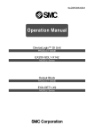
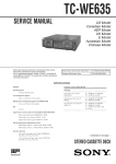
TC-KB820S
SERVICE MANUAL
Dolby noise reduction and HX Pro headroom extension manufactured under license from Dolby
Laboratories Licensing Corporation. HX Pro originated by Bang & Olufsen.
“DOLBY”, the double-D symbol a, and “HX PRO”
are trademarks of Dolby Laboratories Licensing Corporation.
AEP Model
UK Model
Australian Model
Model Name Using Similar Mechanism
Tape Transport Mechanism Type
TC-KE400S
TCM-190VB12CSS
SPECIFICATIONS
– Continued on next page –
STEREO CASSETTE DECK
MICROFILM
Flexible Circuit Board Repairing
• Keep the temperature of the soldering iron around 270 ˚C during repairing.
• Do not touch the soldering iron on the same conductor of the
circuit board (within 3 times).
• Be careful not to apply force on the conductor when soldering
or unsoldering.
Notes on chip component replacement
• Never reuse a disconnected chip component.
• Notice that the minus side of a tantalum capacitor may be damaged by heat.
MODEL IDENTIFICATION
– BACK PANEL –
3-020-983-
AEP Model
: 0 π
UK Model
:1π
Australian Model : 2 π
SAFETY-RELATED COMPONENT WARNING!!
COMPONENTS IDENTIFIED BY MARK ! OR DOTTED
LINE WITH MARK ! ON THE SCHEMATIC DIAGRAMS
AND IN THE PARTS LIST ARE CRITICAL TO SAFE
OPERATION. REPLACE THESE COMPONENTS WITH
SONY PARTS WHOSE PART NUMBERS APPEAR AS
SHOWN IN THIS MANUAL OR IN SUPPLEMENTS PUBLISHED BY SONY.
–2–
TABLE OF CONTENTS
1.
GENERAL ................................................................... 4
2.
DISASSEMBLY ......................................................... 5
3.
MECHANICAL ADJUSTMENTS ....................... 9
4.
ELECTRICAL ADJUSTMENTS ......................... 10
5.
DIAGRAMS
5-1. Note for Printed Wiring Boards and
Schematic Diagrams ....................................................... 14
5-2. Printed Wiring Boards – MD Section – ......................... 15
5-3. Schematic Diagram – MD Section – .............................. 17
5-4. Printed Wiring Board – MAIN Section – ...................... 19
5-5. Schematic Diagram – MAIN Section – (1/3) ................. 21
5-6. Schematic Diagram – MAIN Section – (2/3) ................. 23
5-7. Schematic Diagram – MAIN Section – (3/3) ................. 25
5-8. Printed Wiring Board – DOLBY-S Section – ................ 29
5-9. Schematic Diagram – DOLBY-S Section – .................. 29
5-10. Printed Wiring Boards – PANEL Section – .................. 31
5-11. Schematic Diagram – PANEL Section – ........................ 33
5-12. IC Pin Function Description ........................................... 35
6.
EXPLODED VIEWS ................................................ 37
7.
ELECTRICAL PARTS LIST ............................... 42
–3–
SECTION 1
GENERAL
LOCATION OF CONTROLS
1 I/O (Power) button
8 Cassette holder
2 Remote control sensor
9 § EJECT button
3 PHONES jack
!º AUTO CAL button
4 Display panel
!¡ DOLBY NR switch
5 Tape operation buttons
!™ BALANCE control
AMS* 0 button
!£ REC LEVEL control
· button
AMS* ) button
* AMS is an abbreviation for Automatic Music Sensor.
p button
P PAUSE button
R REC MUTING button
r REC button
6 Tape counter
7 Counter buttons
RESET button
MEMORY button
–4–
SECTION 2
DISASSEMBLY
Note: Follow the disassembly procedure in the numerical order given.
CASE
Unscrew the four case attachment seven tapping screws
and remove the case.
FRONT PANEL SECTION
1 flat cable
(CN801)
3 screw
(BVTP3 × 8)
2 connector
(CN506)
1 flat cable
(CN81)
4 two earth
lugs
2 connector
(CN704)
6 claw
1 flat cable
(CN504)
7 two connectors
(CNP31, 33)
5 four screws
(BVTP3 × 8)
5 screw
(BVTP3 × 8)
8 front panel section
6 claw
MD ASS’Y SECTION
6 Remove the MD ass’y section
to direction of arrow A .
4 two screws
(BVTT2.6 × 8)
A
5 two screws
(BVTP2.6 × 8)
2 two claws
3 cassette lid
ass’y
2 two claws
1 push the eject
button.
–5–
MAIN BOARD
4 two screws
(BVTP3 × 8)
1 connector
(CN701)
5 MAIN board
2 screw
(BV/ring)
4 screw
(BV/ring)
3 bracket (TR)
CASSETTE HOLDER (R) ASS’Y
4 cassette holder (R)
ass’y
2 boss
1 torsion spring
3 shaft
–6–
FITTING BASE BLOCK
2 two screws
(PTPWH2 × 23)
1 connector
(CNP32)
2 screw
(PTPWH2 × 23)
3 fitting base block
Note: When installing, pull
the FR belt and put
around the claws as
shown below.
Note: When installing, pull the capstan belt
and put around the claws as shown below.
HEAD
3 erase head
1 connector
(CNP32)
2 screw
(B2 × 10)
5 record/playback head
6 compression spring
4 azimuth screw
–7–
MOTOR
2 flexible board
(CNP72)
1 connector
(CNP71)
6 capstan motor
!º ground plate
5 two screws
(B2.6 × 3)
4 audio
board
3 claw
8 reel motor
3 claw
9 FR belt
3 two
claws
7 two screws
(P2.6 × 2.8)
–8–
SECTION 3
MECHANICAL ADJUSTMENTS
PRECAUTION
1. Clean the following parts with a denatured alcohol-moistened
swab:
record/playback/erase head pinch roller
rubber belts
capstan
idler
2. Demagnetize the record/playback head with a head demagnetizer.
(Head demagnetizer do not approach for the erase head.)
3. Do not use a magnetized screwdriver for the adjustment.
4. After the adjustments, apply suitable locking compound to the
parts adjusted.
5. The adjustments should be performed with the rated power
supply voltage unless otherwise noted.
• Torque Measurement
Mode
Torque Meter
Meter Reading
Forward
CQ-102C
30 to 60 g•cm
(0.42 to 0.83 oz•inch)
Forward
back
tension
CQ-102C
2 to 7 g•cm
(0.03 to 0.09 oz•inch)
FF/REW
CQ-201B
70 to 110 g•cm
(0.98 to 1.52 oz•inch)
–9–
SECTION 4
ELECTRICAL ADJUSTMENTS
Note: The adjustment should be performed in the order given in the service manual. As a rule, adjustments about playback should be performed before those about recording.
The adjustments should be performed before for both L-CH and RCH.
Record/Playback Head Azimuth Adjustment
Procedure:
1. Mode : FWD playback
Test tape
P-4-A100
(10 kHz, –10 dB)
• Switches and controls should be set as follows unless otherwise
specified.
DOLBY NR, MPX FILTER switch : OFF
• Standard Record:
Deliver the standard input signal level to the input jack and set
the REC LEVEL control to obtain the standard output signal
level.
– Record Mode –
AF OSC
level meter
10 k Ω
attenuator
600 Ω
LINE IN
level meter
47 k Ω
+
–
set
LINE OUT
2. Turn the adjustment screw for the maximum output levels. If
these levels do not match, turn the adjustment screw until both
of output levels match together within 1 dB.
47 k Ω
+
–
set
within
1dB
L-CH
peak
LINE OUT
0 dB = 0.775 V
within
1dB
output
level
Standard Input Level
input terminal
LINE IN
source impedance
10 kΩ
input signal level
0.5 V (–3.8 dB)
Screw
position
R-CH
peak
angle
L-CH peak
R-CH peak
Standard Output Level
output terminal
LINE OUT
load impedance
47 kΩ
output signal level
0.5 V (–3.8 dB)
3. Phase Check
Mode : playback
test tape
P-4-A100
(10 kHz, –10 dB)
Test Tape
Type
Signal
Used for
P-4-A100
10 kHz, –10 dB
Azimuth Adjustment
P-4-L300
315 Hz, 0 dB
Playback Level Adjustment
WS-48B
3 kHz, 0 dB
Tape Speed Adjustment
oscilloscope
L-CH
47 k Ω
set
47 k Ω
V
+
–
+
–
H
R-CH
Test Mode
1. Insert a short-circuit plug into TP801 (2P) and turn ON the
power switch. (Earth pin &ª of IC801 and turn ON the power
switch.)
At first, all the fluorescent tubes light up, then the system returns to normal display. (However, “00 00” is not displayed on
the counter.)
2. To release the test mode, remove the short plug and turn off
the power switch.
3. Remove the short plug after completion of adjustment.
LINE OUT
Screen pattern
in phase 45 ° 90 ° 135 ° 180 °
Good
Wrong
4. After the adjustment, lock the screw with locking compound.
Adjustment Location: Record/Playback head
Adjustment screw
– 10 –
Tape Speed Adjustment
Procedure:
Mode: playback
Bias Consumption Current Adjustment
Procedure:
LINE IN
(no signal)
frequency counter
R-CH
47 k Ω
set
+
–
set
TP81
LINE OUT
1. Set to FWD playback mode.
2. Adjust RV71 so that the frequency counter reading becomes
3,000 ± 90 Hz.
3. If, the frequency counter reading does not become 3,000 ±
90Hz.
Turn RV72 and back to 1st. step again.
Note: Turn RV72 to clockwise – Tape speed becomes fast.
Turn RV72 to counter clockwise – Tape speed becomes slow.
digital voltmeter
CS-413 blank tape
–
+
L-CH
test tape
WS-48B
(3 kHz, 0 dB)
3 2 1
B+ (+7.5 V)
1. Set RV81 (L-CH) and RV91 (R-CH) to mechanical center and
turn the set recording mode.
2. Connect digital voltmeter as shown by the following table.
3. Adjust the following transformers for the minimum readings
on the digital voltmeter.
4. Frequency difference between the beginning and the end of
the tape should be within 1%.
Measurement Point
Adjustment Part
Value
L-CH
1 and 2, TP321
T81
3 and 2, TP321
minimum
R-CH
T91
Adjustment Location: AUDIO board (See page 12.)
Sample value of Wow and Flutter: 0.3% or less W.RMS (JIS)
(WS-48B)
Adjustment Location: AUDIO board (See page 12.)
Playback Level Adjustment
Procedure:
Mode: playback
Record Bias Adjustment
Setting:
REC LEVEL control: Standard Record (See page 10.)
test tape
P-4-L300
(315 Hz, 0 dB)
Procedure:
1. Mode: record
level meter
47 k Ω
AF OSC
+
–
set
Attenuator
LINE OUT
Adjust RV11 (L-CH) and RV21 (R-CH) so that the reading on
level meter meets the adjustment limits below.
LINE IN
315 Hz
50 mV (–23.8 dB)
10 kHz
10 k Ω
600 Ω
CS-123
blank tape
set
2. Mode: playback
Adjustment Limits:
LINE OUT level: –7.7±0.5 dB (0.301 to 0.338 V)
Level difference between channels: within 0.5 dB
Check that the LINE OUT level does not change even if Playback
and Stop operation is repeated several times.
recorded
portion
level meter
47 k Ω
+
–
set
LINE OUT
Adjustment Location: AUDIO board (See page 12.)
3. Adjust RV81(L-CH) and RV91 (R-CH) so that 10 kHz playback output is 0±0.5 dB relative to the 315 Hz output.
Adjustment Location: AUDIO board (See page 12.)
– 11 –
Adjustment Location:
[MAIN BOARD] –COMPONENT SIDE –
Record Level Adjustment
Setting:
REC LEVEL control: Standard Record (See page 10.)
CN831
CN833
DOLBY-S
BOARD
Procedure:
1. Mode: record
LINE IN
315 Hz, 0.5 V (–3.8 dB)
AF OSC
10 k Ω
Attenuator
CS-123
blank tape
set
600 Ω
TP801
RV211 RV111
2. Mode: playback
recorded
portion
level meter
J501
47 k Ω
+
–
set
LINE OUT
[AUDIO BOARD] –SIDE A –
3. Adjust RV111 (L-CH) and RV211 (R-CH) so that the reading
on level meter meets the adjustment limits below.
Adjustment Limits: –3.8 ± 0.5 dB (0.47 to 0.53 V)
RV81 RV91
Adjustment Location: MAIN board
RV72
RV71
T81
IC31
T91
TP81
RV21
RV11
– 12 –
SECTION 5
DIAGRAMS
• Circuit Boards Location
5-1. NOTE FOR PRINTED WIRING BOARDS AND SCHEMATIC DIAGRAMS
(In addition to this, the necessary note is each block.)
Note on Schematic Diagram:
• All capacitors are in µF unless otherwise noted. pF: µµF
50 WV or less are not indicated except for electrolytics
and tantalums.
• All resistors are in Ω and 1/4 W or less unless otherwise
specified.
¢
: internal component.
•
• 2 : nonflammable resistor.
• C : panel designation.
TRANSFORMER board
AC POWER
SW board
AUDIO board
MAIN board
DOLBY-S boards
HP board
PANEL board
LEAF SW board
REC VOL board
– 13 –
Note: The components identified by mark ! or dotted line
with mark ! are critical for safety.
Replace only with part number specified.
• U : B+ Line.
• V : B– Line.
• Voltages and waveforms are dc with respect to ground
under no-signal conditions.
no mark : PB
(
) : REC
: Impossible to measure
∗
• Voltages are taken with a VOM (Input impedance 10 MΩ).
Voltage variations may be noted due to normal production tolerances.
• Waveforms are taken with a oscilloscope.
Voltage variations may be noted due to normal production tolerances.
• Circled numbers refer to waveforms.
• Signal path.
E : PB
a : REC
Note on Printed Wiring Boards:
• X : parts extracted from the component side.
• Y : parts extracted from the conductor side.
r
•
: Through hole.
• b : Pattern from the side which enables seeing.
(The other layers' patterns are not indicated.)
Caution:
Pattern face side:
(Side B)
Parts face side:
(Side A)
Parts on the pattern face side seen from
the pattern face are indicated.
Parts on the parts face side seen from
the parts face are indicated.
• Indication of transistor.
Q
B C
E
These are omitted.
Q
B
C
E
These are omitted.
– 14 –
TC-KB820S
5-2. PRINTED WIRING BOARDS – MD Section –
• See page 13 for Circuit Boards Location.
(Page 20)
(Page 19)
(Page 19)
• Semiconductor
Location
Ref. No.
Location
D31
C-1
IC31
IC81
•IC81
C-2
B-3
G-4
Q51
Q52
Q53
Q71
B-2
B-2
B-2
C-4
(Note) •:LEAF SW BOARD
– 15 –
– 16 –
TC-KB820S
5-3. SCHEMATIC DIAGRAM – MD Section – • See page 27 for Waveforms.
(Page 21)
(Page 21)
(Page 23)
– 17 –
– 18 –
TC-KB820S
5-4. PRINTED WIRING BOARD – MAIN Section –
• Semiconductor
Location
Ref. No.
• See page 13 for Circuit Boards Location.
(Page 31)
(Page 15)
(Page 32)
(Page 15)
(Page 15)
(Page 31)
Location
D131
D132
D231
D232
D511
D512
D513
D551
D701
D702
D703
D704
D705
D706
D707
D708
D709
D710
D711
D712
D713
D714
D715
D801
D802
C-5
C-5
C-5
C-5
B-7
B-7
E-7
B-5
G-2
G-2
G-2
G-2
F-2
F-2
F-2
G-3
G-5
F-3
F-4
F-3
E-1
E-3
F-4
D-2
D-2
IC501
IC502
IC503
IC504
IC505
IC506
IC507
IC508
IC509
IC510
IC511
IC512
IC601
IC701
IC801
IC802
C-9
F-9
D-6
C-5
D-5
A-9
C-7
B-4
C-4
B-6
F-10
D-9
A-3
G-4
B-2
D-2
Q101
Q102
Q103
Q121
Q122
Q201
Q202
Q203
Q221
Q222
Q503
Q511
Q512
Q521
Q531
Q532
Q551
Q572
Q573
Q601
Q701
Q702
Q704
Q705
Q707
Q708
Q805
A-8
B-8
E-8
F-6
D-7
A-8
B-10
E-9
F-6
D-7
E-8
B-6
B-7
F-7
B-5
B-5
A-5
F-7
C-7
B-3
G-6
G-5
G-4
F-3
F-3
F-2
D-2
(Page 29)
(Page 29)
(Page 32)
– 19 –
– 20 –
TC-KB820S
5-5. SCHEMATIC DIAGRAM – MAIN Section – (1/3)
(Page 30)
(Page 23)
(Page 34)
(Page 18)
(Page 18)
(Page 30)
(Page 23)
The components identified by mark ! or dotted
line with mark ! are critical for safety.
Replace only with part number specified.
– 21 –
– 22 –
TC-KB820S
5-6. SCHEMATIC DIAGRAM – MAIN Section – (2/3) • See page 27 for Waveforms.
(Page 22)
(Page 25)
(Page 25)
(Page 22)
(Page 18)
– 23 –
– 24 –
TC-KB820S
5-7. SCHEMATIC DIAGRAM – MAIN Section – (3/3) • See page 28 for IC Block Diagrams.
(Page 34)
(Page 24)
(Page 33)
(Page 33)
(Page 24)
The components identified by mark ! or dotted
line with mark ! are critical for safety.
Replace only with part number specified.
– 25 –
– 26 –
• IC Block Diagrams
SCINL
SCBOL
FBOL
TCS1L
TCS2L
TCF1L
TCF2L
IREF
VCC
30 29
28
27
26 25
24 23
22
21 20
19 18 17
16
MC4IN
ANTSAT
RECOUT
CXA1917AM-T6 (DOLBY-S BOARD)
HLSOUT
IC1
6 IC81 !¡, !™
MCBO
1 T51 1
MC3IN
• Waveforms
– AUDIO BOARD –
118 Vp-p
ANTSAT
6.2 Vp-p
SLDET
FLVCR
9.3 µs
V TO I
CONV H
MC
9.3 µs
SLICG
SLVCR
FLDET
FLICG
MC4
2 Q51 C, Q52 C
MC4
MC3DS
MC3DT
MC2
MC1
MC1
– MAIN BOARD (2/3) –
MC3
1 IC801 #¡
VREF &
IREF
SHDET
LFDET
9
10 11 12 13 14 15
3 T81 4
I.REF
BOOST
13
12
11 10
OUT
IN
16 15 14
VCC
G.CAL
MUTE
R.CAL
IC502 CXA1579P (MAIN BOARD)
63.2 Vp-p
9
VCC
BIAS
REC EQ AMP
9.3 µs
CONTROL
REC EQ AMP
4 T91 4
+
–
VGS
1 2 3
4
5
6
7
8
SPEED
METAL
70US
IN
GND
BOOST
VEE
OUT
VEE
64.8 Vp-p
9.3 µs
5 IC81 7, 8
6.4 Vp-p
9.3 µs
– 27 –
FHICG
TCF1H
TCF2H
TCS2H
TCS1H
VCT
VEE
8
LFIN
6 MHz
6 7
ZL1
ZL2
HLSMP
MCTC
9.3 µs
5
3 4
FHDET
FBOH
1 2
LFICG
SHICG
SHVCR
V TO I
CONV H
LFVCR
SCINH
4.3 Vp-p
FHVCR
TCL1
TCL2
26.4 Vp-p
– 28 –
TC-KB820S
5-8. PRINTED WIRING BOARD – DOLBY-S Section –
• See page 13 for Circuit Boards Location.
5-9. SCHEMATIC DIAGRAM – DOLBY-S Section –
• See page 28 for IC Block Diagrams.
(Page 21)
(Page 20)
– 29 –
– 30 –
TC-KB820S
5-10.
PRINTED WIRING BOARDS – PANEL Section –
• See page 13 for Circuit Boards Location.
(Page 19)
(Page 19)
(Page 32)
(Page 32)
(Page 20)
(Page 19)
– 31 –
– 32 –
TC-KB820S
5-11.
SCHEMATIC DIAGRAM – PANEL Section –
(Page 26)
(Page 21)
(Page 26)
(Page 26)
The components identified by mark ! or dotted
line with mark ! are critical for safety.
Replace only with part number specified.
– 33 –
– 34 –
5-12.
IC PIN FUNCTION DESCRIPTION
• MAIN BOARD IC801 CXP82612-022Q (SYSTEM CONTROLLER)
Pin No.
Pin Name
I/O
Function
1
STOP SW
I
Mechanism stop detect switch (S81) input terminal
2
SIRCS IN
I
Sircs signal input from the remote control receiver (IC901)
3
VERSION2
I
Setting terminal for the version (fixed at “L”)
4 to 6
NC
O
Not used (open)
7
MPX ON/OFF
O
Multiplex filter on/off control signal output terminal
“H”: multiplex filter on
8
CAL ON/OFF
O
Calibration on/off control signal output terminal
“H”: calibration on
9
REC CAL 0
O
10
REC CAL 1
O
Recording calibration up/down control signal output to the CXA1579P (IC502)
“H”: up, “L”: down (high impedance: off)
11
GP CAL 0
O
Pin No.
Pin Name
I/O
Function
43
REC/PB
O
Recording/playback control signal output to the CXA1563S (IC501)
“L”: recording mode, “H”: playback mode
44, 45
NC
O
Not used (open)
46 to 61
S1 to S16
O
Segment drive signal output to the fluorescent indicator tube (FL901)
62
S18
O
Segment drive signal output to the fluorescent indicator tube (FL901)
63 to 65
NC
O
Not used (open)
66 to 70
G5 to G1
O
Grid drive signal output to the fluorescent indicator tube (FL901)
71
V-DISP
—
Power supply terminal for the fluorescent indicator tube drive (–20V)
72
VDD
—
Power supply terminal (+5V)
73, 74
NC
O
Not used (open)
75
VDD
—
Power supply terminal (+5V)
76
POWER IN
I
12
GP CAL 1
O
Equalizer calibration up/down control signal output to the CXA1579P (IC502)
“H”: up, “L”: down (high impedance: off)
13
LINE MUTE
O
Line muting on/off control signal output terminal
14
AMS IN
I
Auto music sensor signal input terminal
15
NC
O
Not used (open)
77
POWER OUT
O
Power on/off control signal output terminal “L”: power on Not used (open)
Record muting on/off control signal output to the CXA1579P (IC502)
78
VDD
—
Power supply terminal (+5V)
79
TEST MODE
I
Setting terminal for the test mode “L”: test mode (Normally: fixed at “H”)
80
VERSION1
I
Setting terminal for the version (fixed at “L”)
“L”: line muting on
“H”: AMS detect
16
REC MUTE
O
17
REEL –
O
“H”: record muting on
18
REEL +
O
19
BIAS
O
Recording bias on/off control signal output terminal
20
RELAY
O
Relay drive signal output for the record/playback selection relay
“L”: playback mode, “H”: recording mode
21
CAL KEY
I
AUTO CAL switch (S921) input terminal
22
METER L
I
Signal input for the level meter drive (L-ch)
23
KEY X
I
Key input terminal (A/D input) (S901 to S904)
24
KEY Y
I
Key input terminal (A/D input) (S905 to S909)
R REC MUTING, ·, P PAUSE, MEMORY, RESET keys input
25
METER R
I
Signal input for the level meter drive (R-ch)
26
DOLBY AD
I
DOLBY NR switch (S922) input terminal (A/D input)
27
HALF
I
Half detect switch (S86) input terminal
28
METAL CHROM
I
Metal detect switch (S83) and CrO2 detect switch (S82) input terminal
29
S.REEL
I
Supply reel rotation pulse input from the rotation detect sensor (IC81)
30
RESET
I
System reset signal input from the reset signal generator (IC802) “L”: reset
“L” is input for several 100 msec after power on, then it changes to “H”
31
XO
O
System clock output terminal (6 MHz)
32
XI
I
System clock input terminal (6 MHz)
33
VSS
—
34
BIAS CAL 0
O
35
BIAS CAL 1
O
36
BIAS CAL 2
O
37
BIAS CAL 3
O
38
CAP.M ON/OFF
O
Capstan motor (M902) on/off control signal output terminal
39
OSC H/L
O
Calibration tone frequency high/low control signal output terminal
40
OSC ON/OFF
O
Calibration tone on/off control signal output terminal
41
BC/S
O
Dolby B and C type or dolby S type selection signal output to the CXA1563S (IC501)
“H”: dolby B and C type, “L”: dolby S type
42
DOLCON
O
Dolby B type or dolby C type selection signal output to the CXA1563S (IC501)
“H”: dolby C type, “L”: dolby off (high impedance: dolby B type)
Reel motor (M901) drive signal output terminal
AC in detect signal input terminal “H”: AC in
“H”: bias on
p, AMS 0, AMS ), r REC keys input
“H”: metal or CrO2
Ground terminal
Equalizer bias calibration control signal output terminal
– 35 –
“H”: motor on
“L”: frequency high
“H”: off, “L”: on
– 36 –
SECTION 6
EXPLODED VIEWS
NOTE:
• -XX and -X mean standardized parts, so they
may have some difference from the original
one.
• Color Indication of Appearance Parts
Example:
KNOB, BALANCE (WHITE) . . . (RED)
↑
↑
Parts Color Cabinet's Color
• Items marked “*” are not stocked since they
are seldom required for routine service. Some
delay should be anticipated when ordering
these items.
• The mechanical parts with no reference number in the exploded views are not supplied.
• Hardware (# mark) list and accessories and
packing materials are given in the last of the
electrical parts list.
The components identified by
mark ! or dotted line with mark
! are critical for safety.
Replace only with part number
specified.
(1) CASE, CHASSIS SECTION
rA: TRANSFORMER board
3
#1
2
4
2
7
2
UK
5
(including rA– rE)
rA
6
11
A
7
AEP
7
#1
11
2
not
supplied
T901
10
not
supplied
Australian
not
supplied
not
supplied
11
#1
not
supplied
FRONT PANEL
SECTION
A
#1
1
#2
1
#1
9
#2
Ref. No.
Part No.
Description
1
2
* 3
* 4
* 5
X-4949-523-1
3-710-901-11
3-021-377-01
A-2007-481-A
A-2007-779-A
FOOT ASSY (F50180S)
SCREW, TAPPING
CASE
DOLBY-S BOARD, COMPLETE
MAIN BOARD, COMPLETE
6
!7
!7
4-966-267-11 BUSHING (FBS001), CORD
1-575-651-21 CORD, POWER (AEP)
1-696-586-11 CORD, POWER (UK)
Remark
Ref. No.
Part No.
Description
!7
* 8
* 8
* 8
9
1-696-845-11
3-020-983-01
3-020-983-11
3-020-983-22
3-703-249-21
CORD, POWER (Australian)
PANEL, BACK (AEP)
PANEL, BACK (UK)
PANEL, BACK (Australian)
SCREW, S TIGHT, +PTTWH (M3X8)
10
11
! T901
4-956-370-12 BAND, PLUG FIXED (UK, Australian)
3-704-515-21 SCREW (BV/RING)
1-427-751-11 TRANSFORMER, POWER
– 37 –
Remark
(2) FRONT PANEL SECTION
rB: AC POWER SW board
rC: HP board
rD: PANEL board
rE: REC VOL board
58
59
MD ASS’Y SECTION
rB
57
58
60
#4
rD
rC
58
56
55
61
58
62
#3
rE
63
54
64
67
65
53
66
58
52
51
Part No.
Description
Part No.
Description
51
52
53
54
55
3-020-978-01
3-020-979-01
X-3374-953-1
4-942-568-41
3-020-971-01
KNOB (REC)
KNOB (BALANCE)
LID ASSY, CASSETTE
EMBLEM (NO.5), SONY
PANEL, FRONT (AEP,UK)
59
60
61
62
63
1-696-456-11
1-590-486-11
3-020-975-01
3-020-977-01
3-933-299-01
WIRE (FLAT TYPE) (31 CORE)
WIRE (FLAT TYPE) (7 CORE)
BUTTON (CONTROL)
BUTTON (AUTO CAL)
KNOB (DIA. 12)
55
56
57
58
3-020-971-21
3-020-980-01
4-922-921-62
4-951-620-01
PANEL, FRONT (Australian)
WINDOW (METER)
BUTTON (POWER)
SCREW (2.6X8), +BVTP
64
65
66
67
X-3375-506-1
3-937-169-01
3-020-976-01
3-354-981-11
BASE (KB820S) ASSY, PANEL
SPRING, TENSION
BUTTON (EJECT)
SPRING (SUS), RING
Ref. No.
Remark
Ref. No.
– 38 –
Remark
(13) MD ASS’Y SECTION
103
TCM-190VB12CSS
102
104
#5
106
107
105
108
101
Ref. No.
101
102
103
104
Part No.
Description
X-3368-119-1
3-354-963-01
1-769-914-11
3-354-957-01
HOLDER (R) ASSY, CASSETTE
DAMPER
WIRE (FLAT TYPE) (9 CORE)
JOINT (LOCK LEVER)
Remark
Ref. No.
Part No.
Description
* 105
106
107
108
3-354-954-01
3-354-962-01
3-354-956-01
3-354-960-01
LEVER (LOCK LEVER R)
SPRING (EJ SAFTY SPRING R)
LEVER (EJ SAFTY LEVER R)
SPRING (LOADING R), TORSION
– 39 –
Remark
(4) MECHANISM DECK SECTION-1
(TCM-190VB12CSS)
161
M902
160
160
not
supplied
160
162
159
not
supplied
158
M901
#7
#8
164
163
165
157
166
167
168
169
156
155
169
171
HE901
170
not
#6
supplied
172
153
154
not supplied
151
not
supplied
152
Ref. No.
Part No.
Description
151
152
153
* 154
155
3-907-362-01
A-2004-673-A
3-343-484-01
3-359-445-11
X-3374-992-1
SPRING, TORSION
DECK (ONE) ASSY, HEAD (including HRP901)
SPRING, COMPRESSION
HOLDER (1 WAY HEAD)
SLIDER (LIMITER) ASSY
156
157
158
159
160
3-363-868-01
X-3367-629-1
3-359-467-01
3-359-436-11
3-359-414-01
SPRING (HEAD CHASSIS), TENSION
FLYWHEEL (FWD) ASSY
BELT (1 WAY FLAT BELT)
BASE (THRUST RETAINER), FITTING
SCREW (+PTPWH 2X23)
161
* 162
163
1-638-983-11 MOTOR FLEXIBLE BOARD
A-2007-780-A AUDIO BOARD, COMPLETE
3-359-466-01 BELT (FR), SQUARE
Remark
Ref. No.
Part No.
Description
* 164
165
166
167
168
1-638-020-11
3-359-430-01
3-575-321-00
3-359-424-01
X-3366-971-1
LEAF SW BOARD
SPRING (CASSETTE RETAINER), LEAF
RETAINER, THRUST, CAPSTAN
GEAR (REV GEAR)
TABLE ASSY (B), REEL
169
170
171
172
HE901
3-362-308-01
3-356-713-01
X-3366-970-1
X-3366-047-1
1-543-673-11
CAP (REEL)
WASHER
TABLE ASSY, REEL
LEVER (PINCH F) ASSY
HEAD, MAGNETIC (ERASE)
M901
M902
X-3363-501-2 MOTOR ASSY (REEL)
X-3374-302-1 MOTOR ASSY (CAPSTAN)
– 40 –
Remark
(5) MECHANISM DECK SECTION-2
(TCM-190VB12CSS)
209
208
206
204
207
205
210
202
203
211
212
213
201
Ref. No.
Part No.
Description
201
202
* 203
204
205
3-359-469-01
X-3359-416-1
3-359-415-01
3-359-454-01
3-359-429-01
SPACER
CHASSIS ASSY, MECHANICAL
SLIDER (TRIGGER SLIDER)
SPRING, TORSION
SLIDER (BRAKE PLATE)
206
207
Remark
3-359-456-01 SPRING (TRIGGER SPRING), TORSION
X-3366-569-1 ARM ASSY, FR
Ref. No.
Part No.
Description
208
209
210
211
212
3-359-419-11
3-359-421-01
3-359-418-01
3-924-185-11
3-936-483-01
GEAR (FR GEAR)
CLUTCH (REEL DISK)
PULLEY (FR PULLEY)
SPRING (FR ARM), TORSION
GEAR (CAM GEAR)
213
3-359-448-01 GEAR (TRIGGER)
– 41 –
Remark
AC POWER SW
SECTION 7
ELECTRICAL PARTS LIST
AUDIO
NOTE:
• Due to standardization, replacements in the
parts list may be different from the parts specified in the diagrams or the components used
on the set.
• -XX and -X mean standardized parts, so they
may have some difference from the original
one.
• RESISTORS
All resistors are in ohms.
METAL: Metal-film resistor.
METAL OXIDE: Metal oxide-film resistor.
F: nonflammable
Ref. No.
! C713
Part No.
• Items marked “*” are not stocked since they
are seldom required for routine service.
Some delay should be anticipated when ordering these items.
• SEMICONDUCTORS
In each case, u: µ, for example:
uA. . : µA. .
uPA. . : µPA. .
uPB. . : µPB. .
uPC. . : µPC. .
uPD. . : µPD. .
• CAPACITORS
uF: µF
• COILS
uH: µH
Description
Remark
Ref. No.
Part No.
When indicating parts by reference
number, please include the board.
Description
Remark
AC POWER SW BOARD
*******************
(Included in MAIN BOARD, COMPLETE)
C89
C90
C91
1-124-234-00 ELECT
1-107-584-11 CERAMIC
1-164-232-11 CERAMIC CHIP
22uF
4PF
0.01uF
20%
16V
0.25PF 500V
50V
< CAPACITOR >
C92
C93
C94
C95
C96
1-136-157-00
1-164-004-11
1-136-439-11
1-136-433-11
1-163-143-00
0.022uF
0.1uF
330PF
100PF
0.0012uF
5%
10%
5%
5%
5%
50V
25V
630V
630V
50V
C97
C98
C99
1-136-273-00 FILM
1-163-003-11 CERAMIC CHIP
1-164-005-11 CERAMIC CHIP
75PF
330PF
0.47uF
5%
10%
630V
50V
25V
1-117-703-11 CERAMIC
0.0047uF 99%
250V
< SWITCH >
! S930
1-762-581-11 SWITCH, AC POWER PUSH (1 KEY) (I/O)
************************************************************
A-2007-780-A AUDIO BOARD, COMPLETE
**********************
*
The components identified by
mark ! or dotted line with mark
! are critical for safety.
Replace only with part number
specified.
FILM
CERAMIC CHIP
FILM
FILM
CERAMIC CHIP
< CONNECTOR >
< CAPACITOR >
C11
C12
C13
C18
C21
1-163-133-00
1-136-157-00
1-124-234-00
1-163-251-11
1-163-133-00
CERAMIC CHIP
FILM
ELECT
CERAMIC CHIP
CERAMIC CHIP
470PF
0.022uF
22uF
100PF
470PF
5%
5%
20%
5%
5%
50V
50V
16V
50V
50V
C22
C23
C28
C31
C32
1-136-157-00
1-124-234-00
1-163-251-11
1-124-234-00
1-124-234-00
FILM
ELECT
CERAMIC CHIP
ELECT
ELECT
0.022uF
22uF
100PF
22uF
22uF
5%
20%
5%
20%
20%
50V
16V
50V
16V
16V
C33
C51
C52
C53
C54
1-124-234-00
1-164-182-11
1-164-182-11
1-163-020-00
1-136-601-11
ELECT
CERAMIC CHIP
CERAMIC CHIP
CERAMIC CHIP
FILM
22uF
0.0033uF
0.0033uF
0.0082uF
0.01uF
20%
10%
10%
10%
5%
16V
50V
50V
50V
630V
C56
C57
C71
C80
C81
1-164-505-11
1-164-346-11
1-164-346-11
1-124-234-00
1-164-232-11
CERAMIC CHIP
CERAMIC CHIP
CERAMIC CHIP
ELECT
CERAMIC CHIP
2.2uF
1uF
1uF
22uF
0.01uF
C82
C83
C84
C85
C86
1-136-157-00
1-164-004-11
1-136-439-11
1-136-433-11
1-163-143-00
FILM
CERAMIC CHIP
FILM
FILM
CERAMIC CHIP
0.022uF
0.1uF
330PF
100PF
0.0012uF
5%
10%
5%
5%
5%
50V
25V
630V
630V
50V
C87
C88
1-136-273-00 FILM
1-163-003-11 CERAMIC CHIP
75PF
330PF
5%
10%
630V
50V
20%
16V
16V
16V
16V
50V
*
*
*
*
CNP31
CNP32
CNP33
CNP71
CNP72
1-580-782-11
1-580-781-11
1-580-782-11
1-564-719-11
1-764-902-11
CONNECTOR, BOARD TO BOARD
PIN, CONNECTOR (PC BOARD) 7P
CONNECTOR, BOARD TO BOARD
PIN, CONNECTOR (SMALL TYPE) 3P
CONNECTOR, FFC/FPC 4P
< DIODE >
D31
8-719-404-46 DIODE MA110
< IC >
IC31
IC81
8-759-711-85 IC NJM4580E-D
8-759-106-56 IC uPC1297CA
< COIL >
L81
L91
1-410-780-11 INDUCTOR
1-410-780-11 INDUCTOR
27mH
27mH
< TRANSISTOR >
Q51
Q52
Q53
Q71
8-729-822-05
8-729-822-05
8-729-822-05
8-729-602-36
TRANSISTOR
TRANSISTOR
TRANSISTOR
TRANSISTOR
2SD1622-ST-TD
2SD1622-ST-TD
2SD1622-ST-TD
2SA1602
< RESISTOR >
R11
R12
R13
R14
R21
– 42 –
1-216-086-00
1-216-025-00
1-216-100-00
1-216-068-00
1-216-086-00
RES, CHIP
RES, CHIP
RES, CHIP
METAL CHIP
RES, CHIP
36K
100
130K
6.2K
36K
5%
5%
5%
5%
5%
1/10W
1/10W
1/10W
1/10W
1/10W
AUDIO
Remark
Ref. No.
5%
5%
5%
5%
5%
1/10W
1/10W
1/10W
1/10W
1/10W
4.7K
56K
56K
10K
5.6
5%
5%
5%
5%
5%
METAL CHIP
METAL CHIP
RES, CHIP
METAL CHIP
RES, CHIP
5.6
2.2
100
1.8K
47K
1-216-089-00
1-216-073-00
1-216-085-00
1-216-001-00
1-216-101-00
RES, CHIP
METAL CHIP
METAL CHIP
METAL CHIP
METAL CHIP
R85
R91
R92
R93
R94
1-216-075-00
1-216-073-00
1-216-085-00
1-216-001-00
1-216-101-00
METAL CHIP
METAL CHIP
METAL CHIP
METAL CHIP
METAL CHIP
R95
1-216-075-00 METAL CHIP
Ref. No.
DOLBY-S
Part No.
Description
C6
C7
C8
C9
C10
1-136-165-00
1-137-372-11
1-164-222-11
1-126-301-11
1-137-442-11
FILM
FILM
CERAMIC CHIP
ELECT
FILM
0.1uF
0.022uF
0.22uF
1uF
0.039uF
20%
5%
50V
50V
25V
50V
50V
1/10W
1/10W
1/10W
1/10W
1/10W
C11
C12
C13
C14
C15
1-163-007-11
1-164-717-11
1-163-038-00
1-124-465-00
1-164-222-11
CERAMIC CHIP
CERAMIC CHIP
CERAMIC CHIP
ELECT
CERAMIC CHIP
680PF
10%
0.0082uF 5%
0.1uF
0.47uF
20%
0.22uF
50V
50V
25V
50V
25V
5%
5%
5%
5%
5%
1/10W
1/10W
1/10W
1/10W
1/10W
C16
C17
C18
C19
C20
1-163-038-00
1-124-465-00
1-163-038-00
1-164-222-11
1-163-035-00
CERAMIC CHIP
ELECT
CERAMIC CHIP
CERAMIC CHIP
CERAMIC CHIP
0.1uF
0.47uF
0.1uF
0.22uF
0.047uF
25V
50V
25V
25V
50V
47K
10K
33K
10
150K
5%
5%
5%
5%
5%
1/10W
1/10W
1/10W
1/10W
1/10W
C21
C22
C23
C24
C25
1-164-717-11
1-164-161-11
1-163-005-11
1-137-442-11
1-136-165-00
CERAMIC CHIP
CERAMIC CHIP
CERAMIC CHIP
FILM
FILM
0.0082uF
0.0022uF
470PF
0.039uF
0.1uF
5%
10%
10%
5%
5%
50V
100V
50V
50V
50V
12K
10K
33K
10
150K
5%
5%
5%
5%
5%
1/10W
1/10W
1/10W
1/10W
1/10W
C26
C28
1-137-372-11 FILM
1-163-038-00 CERAMIC CHIP
0.022uF
0.1uF
5%
50V
25V
12K
5%
1/10W
Part No.
Description
R22
R23
R24
R31
R32
1-216-025-00
1-216-100-00
1-216-068-00
1-216-033-00
1-216-033-00
RES, CHIP
RES, CHIP
METAL CHIP
METAL CHIP
METAL CHIP
100
130K
6.2K
220
220
R33
R51
R52
R53
R54
1-216-065-91
1-216-091-00
1-216-091-00
1-216-073-00
1-216-309-00
RES, CHIP
METAL CHIP
METAL CHIP
METAL CHIP
METAL CHIP
R55
R57
R71
R72
R73
1-216-309-00
1-216-298-00
1-216-025-00
1-216-055-00
1-216-089-00
R74
R81
R82
R83
R84
Remark
5%
5%
20%
< CONNECTOR >
CN1
1-695-092-11 SOCKET, CONNECTOR 7P
< IC >
< VARIABLE RESISTOR >
IC1
RV11
RV12
RV71
RV72
RV81
1-241-761-11
1-241-761-11
1-241-761-11
1-241-762-11
1-241-786-11
RES, ADJ, CARBON 1K
RES, ADJ, CARBON 1K
RES, ADJ, CARBON 1K
RES, ADJ, CARBON 2.2K
RES, ADJ, CARBON 22K
RV91
1-241-786-11 RES, ADJ, CARBON 22K
8-752-076-30 IC CXA1917AM-T6
< SHORT CHIP >
J1
J2
J3
1-216-296-00 SHORT (CHIP) 0
1-216-296-00 SHORT (CHIP) 0
1-216-296-00 SHORT (CHIP) 0
< RESISTOR >
< RELAY >
RY31
1-515-913-11 RELAY
< TRANSFORMER >
T51
T81
T91
1-433-383-11 TRANSFORMER, BIAS OSCILLATION
1-433-398-11 TRANSFORMER, BIAS OSCILLATOR
1-433-398-11 TRANSFORMER, BIAS OSCILLATOR
< TEST PIN >
1-568-449-11 HOUSING, CONNECTOR (PC BOARD) 3P
(TEST TERMINAL)
************************************************************
R1
R2
R3
R4
R5
1-216-685-11
1-208-811-11
1-208-791-11
1-208-799-11
1-216-689-11
METAL CHIP
RES, CHIP
RES, CHIP
RES, CHIP
METAL CHIP
27K
16K
2.4K
5.1K
39K
0.5%
2%
2%
2%
0.5%
1/10W
1/10W
1/10W
1/10W
1/10W
R6
R7
R8
R9
R10
1-216-689-11
1-216-615-11
1-208-462-41
1-208-812-11
1-216-615-11
METAL CHIP
METAL CHIP
RES, CHIP
RES, CHIP
METAL CHIP
39K
33
10K
18K
33
0.5%
0.5%
2%
2%
0.5%
1/10W
1/10W
1/10W
1/10W
1/10W
R11
R12
R13
R14
R15
1-216-619-11
1-216-684-11
1-216-615-11
1-216-619-11
1-216-655-11
METAL CHIP
METAL CHIP
METAL CHIP
METAL CHIP
METAL CHIP
47
24K
33
47
1.5K
0.5%
0.5%
0.5%
0.5%
0.5%
1/10W
1/10W
1/10W
1/10W
1/10W
* TP81
A-2007-481-A DOLBY-S BOARD, COMPLETE
************************
*
< CAPACITOR >
C1
C2
C3
C4
C5
1-136-165-00
1-163-012-00
1-163-012-00
1-164-222-11
1-136-165-00
FILM
CERAMIC CHIP
CERAMIC CHIP
CERAMIC CHIP
FILM
0.1uF
0.0018uF
0.0018uF
0.22uF
0.1uF
5%
10%
10%
5%
50V
50V
50V
25V
50V
R16
1-216-678-11 METAL CHIP
13K
0.5% 1/10W
R17
1-216-673-11 METAL CHIP
8.2K
0.5% 1/10W
R18
1-208-462-41 RES, CHIP
10K
2%
1/10W
R19
1-208-462-41 RES, CHIP
10K
2%
1/10W
R20
1-216-689-11 METAL CHIP
39K
0.5% 1/10W
************************************************************
– 43 –
HP
Ref. No.
LEAF SW
Part No.
MAIN
Description
Remark
HP BOARD
*********
(Included in MAIN BOARD, COMPLETE)
< CAPACITOR >
C133
C233
1-162-294-31 CERAMIC
1-162-294-31 CERAMIC
0.001uF
0.001uF
10%
10%
50V
50V
< JACK >
J502
1-568-519-41 JACK, LARGE TYPE (PHONES)
************************************************************
1-638-020-11 LEAF SW BOARD
**************
*
Ref. No.
Part No.
Description
C116
C131
C132
C201
C202
1-136-170-00
1-126-963-11
1-126-962-11
1-137-372-11
1-126-963-11
FILM
ELECT
ELECT
FILM
ELECT
0.27uF
4.7uF
3.3uF
0.022uF
4.7uF
5%
20%
20%
5%
20%
50V
50V
50V
50V
50V
Remark
C203
C204
C205
C206
C207
1-137-368-11
1-126-964-11
1-136-165-00
1-136-163-00
1-126-965-11
FILM
ELECT
FILM
FILM
ELECT
0.0047uF
10uF
0.1uF
0.068uF
22uF
5%
20%
5%
5%
20%
50V
50V
50V
50V
50V
C208
C209
C210
C211
C212
1-126-964-11
1-126-964-11
1-126-963-11
1-126-962-11
1-126-959-11
ELECT
ELECT
ELECT
ELECT
ELECT
10uF
10uF
4.7uF
3.3uF
0.47uF
20%
20%
20%
20%
20%
50V
50V
50V
50V
50V
C213
C214
C215
C216
C231
1-126-963-11
1-137-436-11
1-137-366-11
1-136-170-00
1-126-963-11
ELECT
FILM
FILM
FILM
ELECT
4.7uF
0.0039uF
0.0022uF
0.27uF
4.7uF
20%
5%
5%
5%
20%
50V
50V
50V
50V
50V
C232
C301
C501
C502
C503
1-126-962-11
1-126-935-11
1-126-935-11
1-126-964-11
1-126-964-11
ELECT
ELECT
ELECT
ELECT
ELECT
3.3uF
470uF
470uF
10uF
10uF
20%
20%
20%
20%
20%
50V
16V
16V
50V
50V
C504
C505
C506
C511
C512
1-126-960-11
1-126-964-11
1-126-925-11
1-137-374-11
1-136-164-00
ELECT
ELECT
ELECT
FILM
FILM
1uF
10uF
470uF
0.047uF
0.082uF
20%
20%
20%
5%
5%
50V
50V
10V
50V
50V
C513
C521
C551
C552
C553
1-137-367-11
1-126-964-11
1-162-282-31
1-161-494-00
1-162-217-31
FILM
ELECT
CERAMIC
CERAMIC
CERAMIC
0.0033uF
10uF
100PF
0.022uF
56PF
5%
20%
10%
50V
50V
50V
25V
50V
C554
C555
C571
C572
C601
1-126-961-11
1-126-961-11
1-126-961-11
1-126-916-11
1-164-159-11
ELECT
ELECT
ELECT
ELECT
CERAMIC
2.2uF
2.2uF
2.2uF
1000uF
0.1uF
20%
20%
20%
20%
50V
50V
50V
6.3V
50V
C602
C701
C702
C703
C704
1-162-288-31
1-126-943-11
1-126-943-11
1-104-664-11
1-126-926-11
CERAMIC
ELECT
ELECT
ELECT
ELECT
330PF
2200uF
2200uF
47uF
1000uF
10%
20%
20%
20%
20%
50V
25V
25V
25V
10V
C705
C706
C707
C708
C709
1-126-926-11
1-126-935-11
1-126-964-11
1-126-963-11
1-126-968-11
ELECT
ELECT
ELECT
ELECT
ELECT
1000uF
470uF
10uF
4.7uF
100uF
20%
20%
20%
20%
20%
10V
6.3V
50V
50V
50V
C710
C711
C801
C805
C806
1-104-664-11
1-164-159-11
1-126-963-11
1-161-494-00
1-126-964-11
ELECT
CERAMIC
ELECT
CERAMIC
ELECT
47uF
0.1uF
4.7uF
0.022uF
10uF
20%
25V
50V
50V
25V
50V
C807
C808
C809
1-126-935-11 ELECT
1-161-494-00 CERAMIC
1-161-494-00 CERAMIC
470uF
0.022uF
0.022uF
20%
< CONNECTOR >
* CNP81
CNP81
1-568-850-11 SOCKET, CONNECTOR 7P
1-695-368-31 PIN, CONNECTOR (PC BOARD) 7P
< IC >
IC81
8-749-924-10 IC PHOTO REFLECTOR NJL5165K-B(H1)
< RESISTOR >
R81
R83
R84
R85
1-249-414-11
1-247-834-11
1-249-417-11
1-249-408-11
CARBON
CARBON
CARBON
CARBON
560
1.3K
1K
180
5%
5%
5%
5%
1/4W
1/4W
1/4W
1/4W
< SWITCH >
S81
S82
S83
S84
S86
1-571-958-11
1-571-281-21
1-571-281-21
1-571-281-21
1-571-281-21
SWITCH, PUSH (1 KEY) (MECHANISM STOP)
SWITCH, LEAF (70u)
SWITCH, LEAF (METAL)
SWITCH, LEAF (REC)
SWITCH, LEAF (HALF)
5%
************************************************************
A-2007-779-A MAIN BOARD, COMPLETE
*********************
(Including AC POWER SW BOARD, HP BOARD,
PANEL BOARD, REC VOL BOARD,
and TRANSFORMER BOARD)
*
< CAPACITOR >
C101
C102
C103
C104
C105
1-137-372-11
1-126-963-11
1-137-368-11
1-126-964-11
1-136-165-00
FILM
ELECT
FILM
ELECT
FILM
0.022uF
4.7uF
0.0047uF
10uF
0.1uF
5%
20%
5%
20%
5%
50V
50V
50V
50V
50V
C106
C107
C108
C109
C110
1-136-163-00
1-126-965-11
1-126-964-11
1-126-964-11
1-126-963-11
FILM
ELECT
ELECT
ELECT
ELECT
0.068uF
22uF
10uF
10uF
4.7uF
5%
20%
20%
20%
20%
50V
50V
50V
50V
50V
C111
C112
C113
C114
C115
1-126-962-11
1-126-959-11
1-126-963-11
1-137-436-11
1-137-366-11
ELECT
ELECT
ELECT
FILM
FILM
3.3uF
0.47uF
4.7uF
0.0039uF
0.0022uF
20%
20%
20%
5%
5%
50V
50V
50V
50V
50V
– 44 –
20%
20%
6.3V
25V
25V
MAIN
Ref. No.
Part No.
Description
Remark
C810
C811
1-162-282-31 CERAMIC
1-164-159-11 CERAMIC
100PF
0.1uF
10%
50V
50V
C812
1-137-374-11 FILM
0.047uF
5%
50V
Ref. No.
Part No.
Description
Remark
IC801
8-752-856-27 IC CXP82612-022Q
IC802
8-759-165-82 IC PST600E-T
< JACK >
< CONNECTOR >
J501
* CN81
CN101
CN201
* CN504
CN506
1-568-826-11
1-695-087-11
1-695-087-11
1-568-828-11
1-506-468-11
SOCKET, CONNECTOR 7P
PIN, CONNECTOR (PC BOARD) 7P
PIN, CONNECTOR (PC BOARD) 7P
SOCKET, CONNECTOR 9P
PIN, CONNECTOR 3P
* CN801
* CNB31
* CNB33
CNE701
CNE701
1-568-845-11
1-691-916-21
1-691-916-21
1-564-510-11
1-764-330-11
SOCKET, CONNECTOR 31P
CONNECTOR, BOARD TO BOARD
CONNECTOR, BOARD TO BOARD
PLUG, CONNECTOR 7P
PIN, CONNECTOR (PCB)(V TYPE)7P
1-784-430-11 JACK, PIN 4P (LINE IN, OUT)
< FILTER >
LPF101 1-233-271-11 FILTER, LOW PASS
LPF201 1-233-271-11 FILTER, LOW PASS
< TRANSISTOR >
< DIODE >
Q101
Q102
Q103
Q121
Q122
8-729-900-89
8-729-900-80
8-729-900-80
8-729-922-37
8-729-119-78
TRANSISTOR
TRANSISTOR
TRANSISTOR
TRANSISTOR
TRANSISTOR
DTC144ES
DTC114ES
DTC114ES
2SD2144S
2SC403SP-51
D131
D132
D231
D232
D511
8-719-911-19
8-719-911-19
8-719-911-19
8-719-911-19
8-719-911-19
DIODE
DIODE
DIODE
DIODE
DIODE
1SS119
1SS119
1SS119
1SS119
1SS119
Q201
Q202
Q203
Q221
Q222
8-729-900-89
8-729-900-80
8-729-900-80
8-729-922-37
8-729-119-78
TRANSISTOR
TRANSISTOR
TRANSISTOR
TRANSISTOR
TRANSISTOR
DTC144ES
DTC114ES
DTC114ES
2SD2144S
2SC403SP-51
D512
D513
D551
D701
D702
8-719-911-19
8-719-911-19
8-719-911-19
8-719-024-99
8-719-024-99
DIODE
DIODE
DIODE
DIODE
DIODE
1SS119
1SS119
1SS119
11ES2-NTA2B
11ES2-NTA2B
Q503
Q511
Q512
Q521
Q531
8-729-422-57
8-729-119-78
8-729-900-74
8-729-900-80
8-729-422-57
TRANSISTOR
TRANSISTOR
TRANSISTOR
TRANSISTOR
TRANSISTOR
UN4111
2SC403SP-51
DTC143TS
DTC114ES
UN4111
D703
D704
D705
D706
D707
8-719-024-99
8-719-024-99
8-719-024-99
8-719-024-99
8-719-024-99
DIODE
DIODE
DIODE
DIODE
DIODE
11ES2-NTA2B
11ES2-NTA2B
11ES2-NTA2B
11ES2-NTA2B
11ES2-NTA2B
Q532
Q551
Q572
Q573
Q601
8-729-900-80
8-729-119-76
8-729-422-57
8-729-900-65
8-729-801-93
TRANSISTOR
TRANSISTOR
TRANSISTOR
TRANSISTOR
TRANSISTOR
DTC114ES
2SA1175-HFE
UN4111
DTA144ES
2SD1387
D708
D709
D710
D711
D712
8-719-933-33
8-719-986-05
8-719-985-88
8-719-911-19
8-719-911-19
DIODE
DIODE
DIODE
DIODE
DIODE
HZS6A1L
HZS9A2LTA
HZS6B2LTA
1SS119
1SS119
Q701
Q702
Q704
Q705
Q707
8-729-141-83
8-729-209-15
8-729-141-83
8-729-119-78
8-729-119-76
TRANSISTOR
TRANSISTOR
TRANSISTOR
TRANSISTOR
TRANSISTOR
2SB1094-LK
2SD2012
2SB1094-LK
2SC403SP-51
2SA1175-HFE
D713
D714
D715
D801
D802
8-719-986-00
8-719-911-19
8-719-985-41
8-719-933-33
8-719-933-33
DIODE
DIODE
DIODE
DIODE
DIODE
HZS7C1LTA
1SS119
HZS2CLL
HZS6A1L
HZS6A1L
Q708
Q805
8-729-140-04 TRANSISTOR 2SB1116A-L
8-729-119-76 TRANSISTOR 2SA1175-HFE
< IC >
IC501
IC502
IC503
IC504
IC505
8-752-066-35
8-752-055-62
8-759-634-51
8-759-634-51
8-759-634-51
IC
IC
IC
IC
IC
CXA1563S
CXA1579P
M5218AP
M5218AP
M5218AP
IC506
IC507
IC508
IC509
IC510
8-759-140-53
8-759-634-51
8-759-000-48
8-759-916-14
8-759-634-51
IC
IC
IC
IC
IC
uPD4053BC
M5218AP
MC14052BCP
SN74HC04AN
M5218AP
IC511
IC512
IC601
IC701
8-759-634-51
8-759-634-51
8-759-803-42
8-759-634-51
IC
IC
IC
IC
M5218AP
M5218AP
LA6500-FA
M5218AP
< RESISTOR >
R101
R102
R104
R105
R106
1-247-838-00
1-247-843-11
1-249-417-11
1-249-420-11
1-247-887-00
CARBON
CARBON
CARBON
CARBON
CARBON
2K
3.3K
1K
1.8K
220K
5%
5%
5%
5%
5%
1/4W
1/4W
1/4W
1/4W
1/4W
R107
R108
R110
R111
R112
1-247-846-11
1-249-429-11
1-249-429-11
1-249-427-11
1-247-864-11
CARBON
CARBON
CARBON
CARBON
CARBON
4.3K
10K
10K
6.8K
24K
5%
5%
5%
5%
5%
1/4W
1/4W
1/4W
1/4W
1/4W
R113
R114
R115
R116
R121
1-249-429-11
1-249-437-11
1-249-433-11
1-249-434-11
1-249-437-11
CARBON
CARBON
CARBON
CARBON
CARBON
10K
47K
22K
27K
47K
5%
5%
5%
5%
5%
1/4W
1/4W
1/4W
1/4W
1/4W
R122
1-249-421-11 CARBON
2.2K
5%
1/4W
– 45 –
MAIN
Ref. No.
Part No.
Description
R123
R124
R125
R131
1-249-421-11
1-249-437-11
1-249-425-11
1-249-425-11
CARBON
CARBON
CARBON
CARBON
2.2K
47K
4.7K
4.7K
5%
5%
5%
5%
1/4W
1/4W
1/4W
1/4W
Remark
R132
R133
R134
R135
R136
1-247-822-11
1-247-866-11
1-249-435-11
1-249-439-11
1-249-410-11
CARBON
CARBON
CARBON
CARBON
CARBON
430
30K
33K
68K
270
5%
5%
5%
5%
5%
1/4W
1/4W
1/4W
1/4W
1/4W
R141
R143
R144
R145
R151
1-249-432-11
1-249-432-11
1-247-848-11
1-249-409-11
1-249-433-11
CARBON
CARBON
CARBON
CARBON
CARBON
18K
18K
5.1K
220
22K
5%
5%
5%
5%
5%
1/4W
1/4W
1/4W
1/4W
1/4W
R152
R153
R154
R201
R202
1-249-417-11
1-249-441-11
1-249-433-11
1-247-838-00
1-247-843-11
CARBON
CARBON
CARBON
CARBON
CARBON
1K
100K
22K
2K
3.3K
5%
5%
5%
5%
5%
1/4W
1/4W
1/4W
1/4W
1/4W
R204
R205
R206
R207
R208
1-249-417-11
1-249-420-11
1-247-887-00
1-247-846-11
1-249-429-11
CARBON
CARBON
CARBON
CARBON
CARBON
1K
1.8K
220K
4.3K
10K
5%
5%
5%
5%
5%
1/4W
1/4W
1/4W
1/4W
1/4W
R210
R211
R212
R213
R214
1-249-429-11
1-249-427-11
1-247-864-11
1-249-429-11
1-249-437-11
CARBON
CARBON
CARBON
CARBON
CARBON
10K
6.8K
24K
10K
47K
5%
5%
5%
5%
5%
1/4W
1/4W
1/4W
1/4W
1/4W
R215
R216
R221
R222
R223
1-249-433-11
1-249-434-11
1-249-437-11
1-249-421-11
1-249-421-11
CARBON
CARBON
CARBON
CARBON
CARBON
22K
27K
47K
2.2K
2.2K
5%
5%
5%
5%
5%
1/4W
1/4W
1/4W
1/4W
1/4W
R224
R225
R231
R232
R233
1-249-437-11
1-249-425-11
1-249-425-11
1-247-822-11
1-247-866-11
CARBON
CARBON
CARBON
CARBON
CARBON
47K
4.7K
4.7K
430
30K
5%
5%
5%
5%
5%
1/4W
1/4W
1/4W
1/4W
1/4W
R234
R235
R236
R241
R243
1-249-435-11
1-249-439-11
1-249-410-11
1-249-432-11
1-249-432-11
CARBON
CARBON
CARBON
CARBON
CARBON
33K
68K
270
18K
18K
5%
5%
5%
5%
5%
1/4W
1/4W
1/4W
1/4W
1/4W
R244
R245
R251
R252
R253
1-247-848-11
1-249-409-11
1-249-433-11
1-249-417-11
1-249-441-11
CARBON
CARBON
CARBON
CARBON
CARBON
5.1K
220
22K
1K
100K
5%
5%
5%
5%
5%
1/4W
1/4W
1/4W
1/4W
1/4W
R254
!R502
! R503
R505
R512
1-249-433-11
1-215-452-00
1-215-455-00
1-249-417-11
1-249-421-11
CARBON
METAL
METAL
CARBON
CARBON
22K
20K
27K
1K
2.2K
5%
1%
1%
5%
5%
1/4W
1/4W F
1/4W F
1/4W
1/4W
R513
R514
R515
R516
1-249-441-11
1-249-441-11
1-249-436-11
1-249-425-11
CARBON
CARBON
CARBON
CARBON
100K
100K
39K
4.7K
5%
5%
5%
5%
1/4W
1/4W
1/4W
1/4W
Ref. No.
Part No.
Description
Remark
R517
1-249-433-11 CARBON
22K
5%
1/4W
R518
R521
R522
R523
R524
1-249-425-11
1-249-426-11
1-249-426-11
1-247-858-11
1-247-852-11
CARBON
CARBON
CARBON
CARBON
CARBON
4.7K
5.6K
5.6K
13K
7.5K
5%
5%
5%
5%
5%
1/4W
1/4W
1/4W
1/4W
1/4W
R525
R526
R527
R528
R529
1-247-854-11
1-247-854-11
1-249-426-11
1-249-422-11
1-249-429-11
CARBON
CARBON
CARBON
CARBON
CARBON
9.1K
9.1K
5.6K
2.7K
10K
5%
5%
5%
5%
5%
1/4W
1/4W
1/4W
1/4W
1/4W
R530
R531
R532
R535
R536
1-249-421-11
1-249-426-11
1-247-864-11
1-249-419-11
1-249-421-11
CARBON
CARBON
CARBON
CARBON
CARBON
2.2K
5.6K
24K
1.5K
2.2K
5%
5%
5%
5%
5%
1/4W
1/4W
1/4W
1/4W
1/4W
R537
R538
R539
R540
R541
1-247-866-11
1-247-852-11
1-249-431-11
1-247-874-11
1-249-429-11
CARBON
CARBON
CARBON
CARBON
CARBON
30K
7.5K
15K
62K
10K
5%
5%
5%
5%
5%
1/4W
1/4W
1/4W
1/4W
1/4W
R542
R543
R544
R553
R555
1-249-429-11
1-249-429-11
1-249-429-11
1-249-437-11
1-249-427-11
CARBON
CARBON
CARBON
CARBON
CARBON
10K
10K
10K
47K
6.8K
5%
5%
5%
5%
5%
1/4W
1/4W
1/4W
1/4W
1/4W
R556
R557
R558
R559
R560
1-247-843-11
1-249-441-11
1-249-429-11
1-249-441-11
1-249-417-11
CARBON
CARBON
CARBON
CARBON
CARBON
3.3K
100K
10K
100K
1K
5%
5%
5%
5%
5%
1/4W
1/4W
1/4W
1/4W
1/4W
R561
R562
R572
R573
R574
1-249-432-11
1-249-436-11
1-249-429-11
1-249-429-11
1-249-435-11
CARBON
CARBON
CARBON
CARBON
CARBON
18K
39K
10K
10K
33K
5%
5%
5%
5%
5%
1/4W
1/4W
1/4W
1/4W
1/4W
R575
R576
R577
R578
R601
1-247-807-31
1-249-435-11
1-249-429-11
1-249-433-11
1-249-419-11
CARBON
CARBON
CARBON
CARBON
CARBON
100
33K
10K
22K
1.5K
5%
5%
5%
5%
5%
1/4W
1/4W
1/4W
1/4W
1/4W
R602
R603
R604
R605
R606
1-249-429-11
1-247-807-31
1-249-433-11
1-249-433-11
1-249-430-11
CARBON
CARBON
CARBON
CARBON
CARBON
10K
100
22K
22K
12K
5%
5%
5%
5%
5%
1/4W
1/4W
1/4W
1/4W
1/4W
R607
R608
R609
R701
R702
1-249-433-11
1-247-862-11
1-249-429-11
1-249-425-11
1-249-419-11
CARBON
CARBON
CARBON
CARBON
CARBON
22K
20K
10K
4.7K
1.5K
5%
5%
5%
5%
5%
1/4W
1/4W
1/4W
1/4W
1/4W
R703
R704
R705
R706
R707
1-249-418-11
1-249-427-11
1-249-419-11
1-249-419-11
1-249-429-11
CARBON
CARBON
CARBON
CARBON
CARBON
1.2K
6.8K
1.5K
1.5K
10K
5%
5%
5%
5%
5%
1/4W
1/4W
1/4W
1/4W
1/4W
R708
1-249-425-11 CARBON
4.7K
5%
1/4W
– 46 –
The components identified by
mark ! or dotted line with
mark ! are critical for safety.
Replace only with part number specified.
MAIN
Ref. No.
Part No.
Description
R709
R710
R711
R712
1-249-409-11
1-249-417-11
1-249-427-11
1-249-427-11
CARBON
CARBON
CARBON
CARBON
220
1K
6.8K
6.8K
5%
5%
5%
5%
1/4W
1/4W
1/4W
1/4W
Remark
R713
R715
R716
R717
R718
1-249-421-11
1-249-421-11
1-249-437-11
1-249-429-11
1-247-870-11
CARBON
CARBON
CARBON
CARBON
CARBON
2.2K
2.2K
47K
10K
43K
5%
5%
5%
5%
5%
1/4W
1/4W
1/4W
1/4W
1/4W
R719
R801
R802
R803
R805
1-249-429-11
1-249-417-11
1-249-441-11
1-249-429-11
1-249-434-11
CARBON
CARBON
CARBON
CARBON
CARBON
10K
1K
100K
10K
27K
5%
5%
5%
5%
5%
1/4W
1/4W
1/4W
1/4W
1/4W
R806
R807
R808
R809
R810
1-249-434-11
1-249-434-11
1-249-434-11
1-249-434-11
1-247-807-31
CARBON
CARBON
CARBON
CARBON
CARBON
27K
27K
27K
27K
100
5%
5%
5%
5%
5%
1/4W
1/4W
1/4W
1/4W
1/4W
R811
R812
R813
R814
R815
1-247-807-31
1-247-807-31
1-247-807-31
1-247-807-31
1-247-807-31
CARBON
CARBON
CARBON
CARBON
CARBON
100
100
100
100
100
5%
5%
5%
5%
5%
1/4W
1/4W
1/4W
1/4W
1/4W
R816
R821
R822
R823
R824
1-247-807-31
1-249-429-11
1-249-429-11
1-249-429-11
1-249-421-11
CARBON
CARBON
CARBON
CARBON
CARBON
100
10K
10K
10K
2.2K
5%
5%
5%
5%
5%
1/4W
1/4W
1/4W
1/4W
1/4W
R825
R826
R827
R828
R829
1-249-435-11
1-249-421-11
1-249-422-11
1-249-422-11
1-249-422-11
CARBON
CARBON
CARBON
CARBON
CARBON
33K
2.2K
2.7K
2.7K
2.7K
5%
5%
5%
5%
5%
1/4W
1/4W
1/4W
1/4W
1/4W
R830
R831
R832
R833
1-249-429-11
1-249-429-11
1-249-437-11
1-249-437-11
CARBON
CARBON
CARBON
CARBON
10K
10K
47K
47K
5%
5%
5%
5%
1/4W
1/4W
1/4W
1/4W
* CN901
Description
Remark
1-568-845-11 SOCKET, CONNECTOR 31P
< FILTER >
FL901
1-517-374-11 INDICATOR TUBE, FLUORESCENT
< IC >
IC901
8-749-014-66 IC NJL56H400
< RESISTOR >
R902
R903
R904
R905
R906
1-247-848-11
1-249-426-11
1-249-429-11
1-249-435-11
1-249-420-11
CARBON
CARBON
CARBON
CARBON
CARBON
5.1K
5.6K
10K
33K
1.8K
5%
5%
5%
5%
5%
1/4W
1/4W
1/4W
1/4W
1/4W
R907
R908
R927
R928
1-247-843-11
1-249-426-11
1-247-807-31
1-247-807-31
CARBON
CARBON
CARBON
CARBON
3.3K
5.6K
100
100
5%
5%
5%
5%
1/4W
1/4W
1/4W
1/4W
< SWITCH >
S901
S902
S903
S904
S905
1-572-184-11
1-572-184-11
1-572-184-11
1-572-184-11
1-572-184-11
SWITCH, KEYBOARD (p)
SWITCH, KEYBOARD (AMS, 0)
SWITCH, KEYBOARD (AMS, ))
SWITCH, KEYBOARD (r, REC)
SWITCH, KEYBOARD (R, REC MUTING)
S906
1-572-184-11 SWITCH, KEYBOARD (·)
S907
1-572-184-11 SWITCH, KEYBOARD (P, PAUSE)
S908
1-572-184-11 SWITCH, KEYBOARD (MEMORY)
S909
1-572-184-11 SWITCH, KEYBOARD (RESET)
************************************************************
REC VOL BOARD
**************
(Included in MAIN BOARD, COMPLETE)
< CONNECTOR >
* CN904
1-568-828-11 SOCKET, CONNECTOR 9P
< RESISTOR >
1-241-765-11 RES, ADJ, CARBON 22K
1-241-765-11 RES, ADJ, CARBON 22K
< TEST PIN >
* TP801
Part No.
REC VOL
< CONNECTOR >
< VARIABLE RESISTOR >
RV111
RV211
Ref. No.
PANEL
1-560-060-00 PIN, CONNECTOR 2P (TEST TERMINAL)
R921
R922
R923
R924
R925
1-249-430-11
1-249-427-11
1-247-843-11
1-247-868-11
1-247-836-11
CARBON
CARBON
CARBON
CARBON
CARBON
12K
6.8K
3.3K
36K
1.6K
5%
5%
5%
5%
5%
1/4W
1/4W
1/4W
1/4W
1/4W
R926
1-249-421-11 CARBON
2.2K
5%
1/4W
< VIBRATOR >
X801
1-577-360-11 VIBRATOR, CERAMIC (6MHz)
************************************************************
PANEL BOARD
************
(Included in MAIN BOARD, COMPLETE)
< VARIABLE RESISTOR >
RV901
RV902
1-225-607-11 RES, VAR, CARBON 10K/10K (REC LEVEL)
1-223-605-11 RES, VAR, CARBON 20K/20K (BALANCE)
< SWITCH >
3-377-337-11 HOLDER (FL)
*
S921
1-572-184-11 SWITCH, KEYBOARD (AUTO CAL)
S922
1-762-647-11 SWITCH, ROTARY (DOLBY NR)
************************************************************
< CAPACITOR >
C901
1-104-665-11 ELECT
100uF
20%
10V
– 47 –
TC-KB820S
TRANSFORMER
Ref. No.
Part No.
Description
Remark
Ref. No.
Part No.
Description
Remark
TRANSFORMER BOARD
*******************
(Included in MAIN BOARD, COMPLETE)
3-923-762-11 HOLDER (TR)
*
< CAPACITOR >
C712
C714
C715
1-161-494-00 CERAMIC
1-136-169-00 FILM
1-136-169-00 FILM
0.022uF
0.22uF
0.22uF
5%
5%
25V
50V
50V
< CONNECTOR >
* CN702 1-580-230-31 PIN, CONNECTOR (PC BOARD) 2P
CN704 1-568-226-11 PIN, CONNECTOR 2P
************************************************************
MISCELLANEOUS
**************
!7
!7
!7
59
60
103
152
161
M901
M902
1-575-651-21
1-696-586-11
1-696-845-11
1-696-456-11
1-590-486-11
CORD, POWER (AEP)
CORD, POWER (UK)
CORD, POWER (Australian)
WIRE (FLAT TYPE) (31 CORE)
WIRE (FLAT TYPE) (7 CORE)
1-769-914-11
A-2004-673-A
1-638-983-11
X-3363-501-2
X-3374-302-1
WIRE (FLAT TYPE)(9 CORE)
DECK (ONE) ASSY, HEAD (including HRP901)
MOTOR FLEXIBLE BOARD
MOTOR ASSY (REEL)
MOTOR ASSY (CAPSTAN)
! T901
1-427-751-11 TRANSFORMER, POWER
************************************************************
**************
HARDWARE LIST
**************
#1
#2
#3
#4
#5
7-685-646-79
7-685-885-09
7-685-863-09
7-685-134-19
7-685-862-09
SCREW +BVTP 3X8 TYPE2 N-S
SCREW +BVTT 4X16 (S)
SCREW +BVTT 2.6X8 (S)
SCREW +PTPWH 2.6X8 (TYPE2)
SCREW +BVTT 2.6X6 (S)
#6
7-621-772-58 SCREW (+B 2X10)
#7
7-621-775-00 SCREW +B 2.6X3
#8
7-627-556-08 SCREW +P 2.6X2.8
************************************************************
ACCESSORIES & PACKING MATERIALS
*******************************
1-776-263-11 CORD, CONNECTION (AUDIO) 1.5m
3-861-966-11 MANUAL, INSTRUCTIONS (ENGLISH, FRENCH,
SPANISH, PORTUGUESE)
3-861-966-21 MANUAL, INSTRUCTIONS (GERMAN, DUTCH,
SWEDISH, ITALIAN) (AEP)
The components identified by
mark ! or dotted line with
mark ! are critical for safety.
Replace only with part number specified.
Sony Corporation
9-922-817-11
Home A&V Products Company
– 48 –
98D0553-1
Printed in Japan © 1998.4
Published by Quality Assurance Dept.
(Shibaura)