1
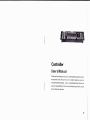
Controller
Users Manual
Thank you for choosing our product, please carefully read this manual
and operate it obey the specification in orderto make sure you can
correct and safety installing. operating and maintaining it; we will not
take any responsibility for the damage and body injury which caused
by the abnormal operation.
AO
Preface
This Manual includes thc important information of inslirll;rlrorr irr.r.l olrr;r;rtion.
Please insta ll a n d ope ral c lhe controller accord ing to t ho in:r lr uo lton:; ri tr rr:lly. And
it must be power oif wlrcrr open the controller oT belorr: rclr;rir.
A:Please read the complclc oontents of this manrral ( plr:;r:;c kcclr llrr; rrr;rntral
attach with the conlrollcr f or any preview )
B:lnordertomakesurethooorrectandsafetyinstallation ol)or;rl orr;rnrlrr;rrnlr:ll;tnce,
well know and follow to the instructions of Manu;rl i:; nrrr:cr;:;;ly
C:We willnot take any rr-.sponsibility to the controller
rl;rnrrr;c l)r()l)r)rlV o1;:r oT
bodyinjurewhichcattscri bytheincorrectinstallation.. ol)or;tlr()n;rrrllr,rlrlcn;r1ce.
tr tlrr,r:orrlluro[is
improvement,andwe'll nolmakeanothernotice.Wcwr IIcr,pllrcrrrlltl lo;tny
NOTICE:The data whir:lt irtside the Manual maybe charrrllrlrlrrr:
specif ication updale rl,rrrrrq rmprovement.
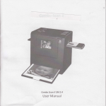
OOutline Size:48.2 x 13.2 x 7cm
Packing Size: 57 x 17.5 x 9cm
ON/W:2.4K9
llation
First, put the controller on the special desk, and then connect the controller and
the light through the signal line.
OConnection of AC adapter
The exclusive AC adapter should be used between the connection of controller and
po\ir'er, and please conf irm if the rated voltage and f requency is accordance with the
power supply. Parameter of Input Voltage and Frequency,
O lnsta
2:Signal Cable('1 PCS)
3: User's manual (l PCS)
4:Maintenance Carri( 1 F']CS)
OUnpacking lnstructiorr,
Please check if ;rll thc contents are completed after unpackrrrl llr,;1, r lrcr:L if the
controller is undarttac,;orl'l Please you can keep the original 1r;rr:l,rr1r,l)(l r{)l{lrn to
the factory if it's r1;rnr;rr1r:ri
OAC Power:Cher;k wlrclhor the voltage is accordance willt Ilrr r,rlrrl;rowor.
OSafety Specifications:irll llrr: safety items of operation(lrrlrrrlr., rrr:,t;rll;rlron)and
before operating.
.Unpackingthecarlottitttrll;tkeoutalltheaccessories,:)rrrlolrr,rrllrrlrollzlr,ri;kage,
take outthe light lrottt lltc oirrton, and put it in a cerlitrn lrl,rtlorrrr l()t ()l,i.r,rtion.
2.Thecontrollerntustkcclrriry;rndavoidtouseundertltcMor.,l ()vr:rlrr;rtor Dusty
'1
surroundings. Anrl kcclr rl l;rr itway f rom the water or otlrlr lrrlrrrrl
3.The installation. opr:r;rltor irrtd maintenance must bc nr,nr,r(lr,rllry tlrrr rlualified
professional, and rir;rko:;ur{) lo operate it under the irr:,llt( I ()trol llrr Mirpual.
4.Please check if the voll:rr1r: r;;tccordance with the rir lcrllrowr'; lrrlotc irr:;talling
Notice:Please make sure it's power off before any installation rcpair and clean!
lntroduction
O Controller Channels l1)2 r:lr;tnnels
O Display:
Voltaqe
I
nCt 00 - 240V
I
|
Frequency
60Hz/50H2
Operation
Production ntroduction
1 . There is 192 DMX channel adjusting output level in every SCENE.
2. B SCENES are available to be programmed for each BANK. When SCENE running,
allprogrammed SCENE of one BANK willbe executed continuously in a cycle.
ll Selectbankusing 1 and J button, Alsoyou canselectdesired bankusing MlDl
signals through MlDl interface ,there are totally 30 banks, once only one can be
I
r;hose.
4. SCENES can be executed automatically, and the duration is dependent on
fAP SYNC/DISPLAY, scenes are executed under music or NOTE triggering, also
f)ress a scene buttons by hand to run scenes.
5 -lhere are total6 chases, each contains240 scenes. You can choose CHASES.
Running one or more, and MlDlsignalremote controlling.
Pane button f unction introduction.
.4 digits LED display
ll
l)r;lrow:;:;(icnes.
4.The second. third, lrrrrrtlrrlrrlil of LED show steJ):r or 0 2lrlr or
OAdditional Function
1.30 Banks each compo:;r:rlol ti l)rogrammable sccnr::r.
2.8 fades adjusting out[)rl lcv{)l
3.Built in Microphone
4.AUTO mode is controlli:rllry IAP SYNCand SPETD controllcrl
5.MlDl controlthrough Mll)l rltorf ace.
1
lnput Voltage:AC 1 00-240V,60H2/50H2
Output Voltage and current : 9V ,1 .0A
lnstallation
(accessories)
1:AC adapter (1PCS)
2.Firddigitof LEDshow:;(:llnS;FS,theseconddigitol
3.Third and fourth digit ol I I l) :;lrows BANKS.
Technology Parameter
OAC adapter
G/W:3Kg
OPacking Content
1
6.Blackout master controlled by M annualor R emote.
T.CHASE programming and CHASE runnyng, manualcontrol and renote control.
B.Fade Time control.
9.DMX polarity selects
OAppearance: use the streamline design
llM[.
FT
t
lFHi-li
I
----2rtrrort
l,it.il
Press SCANNER button, corresponding LED is lit,and the output of continuous B
channels ls enabled to be adjusted, when SCENES are running ,if ad.lustable
I
j
t''
o
il
l
I
ltr
I
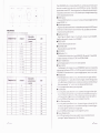
OSCANNERS
DMX channel buttons;rs llte followino list:
Compuier light
cha nnel
1
'1
6
11
32
.).) +o
49 64
ef.,
-
SO
B1 96
9/ 12
r13-'l 28
1
t?9
1,1
r(i1
t//
Computer light
144
5-1
176
192
chan nel
Adjustable
potentiometer
control
ot
OFF
OFF
OFF
OFF
OFF
OFF
OFF
OFF
OFF
OFF
Adjustable
potentiometer
control
t2
3
ON
4
(;4
5
fi0
t)
{)G
7
128
10
1
I
11
1?
ON
ON
B
ON
ON
116
192
OSPEED SLIDER
OFF
OFF
OFF
OFF
OFF
ON
2
LED
ON
ON
ON
potentiometer control is OFF , channel output level is not af f ected by the potentiometer,
if adjustable potentiometer control is ON, channel output is changed correspondingly
with the adjustable potentiometer.
OSCENES button
Press one SCENE button to run scene or to store, and the second digital tube head
display SCENES 1-8.
OAdjustable potentiometer
Reg u lator a d ju sta b le potentiometer to change the output range of the DMX cha n n el,
the minimum is 0 the maximum is 255 or f rom O to 100, adjustable potentiometer
1 -B control continuous B channels.
O Page/Selector button
Select Page A or Page B, Page A is the former B-channel of each SCANNER;
Page B is afterwards B-channel of each SCANNER.
F
OFF
OFF
FF
OFF
oft
OFF
OTF
Move the slider to adjust light speed.
OFADE TIME SIDER
Move the slider to adjust FADE TIME
OLED DISPLAY
aBANKbutton(1/i)
The third and f ourth digital tube display BANKS (01-30), press the ? / ? keys, BANK
increase or decrease, the display SCENE is the SCENE of BANK.
OChasel Chase6 button
Used to Chases program or the choice of Chases operation
O Program button
Turnthepoweron,itisinmanualmode,pressPROGRAMfor2seconds, corresponding
programming light f lashes, SCEN E and CHASE are ready to be programmed, press
PROGRAM f or 2 seconds once more, programming light goes out, return to run mode.
OMidi/add button
A Press Midi button for 2s when running ,the third and f ourth digitaltube f lash,
select channel by 1or 1 , press Midrbtrtton for 2s again, end the settings options
of the Midichannel, the Midichannel is stored. orany button can end the setting of
Midi channel except 1 or 1,and do not storethe selected Midi channel.
ll tJ:;ed to program when under programming mode.
OArrlo/Del button
A lrr running mode, press Auto/Del button, automatically trigger indicator light,
wlrich indicates under automatrc trigger mode, press Auto/Del button again, to
wrllrdraw automatic trigger mode, automatically trigger indicator light goes out.
ll tJsed to SCENE and Chase program when in programming mode.
OMLrsic /Bank copy button
A.ln rtrnning mode, press Music button, the sound triggers indicator light, the
SCENES can be triggered by sound. press Music button again, the sound triggers
the indicator light off, exit the sound trigger state.
B.Used to SCENE and Chase program under programming mode.
OTapsync /Display button
A.ln AUTO running mode, the running speed of scene is decided bythe last
pressing of Tapsync /Display button,Max.l 0 minutes.
;2.t-4
22',;i'',r,
B.Not in AUTO mode, conversion 0-255 or 0-1 00
OBlackout button
Ban on all of the channel output. But does not affect
then click the Blackout key to exit the Blackout mode
OMIDI input
a
O Copya BANK
1 .select the BANK which need to copy.
2.Press Music /Bank copy button.
variely ol opt:rations, and
O Delete a BANK
Midisignalinput
select the BANK which need to delete,press Auto/Del button and Music/Bank copy
button at the same time.
ODI\4X polarity select
Select DMX polarity of the output
CHASES PROGRAMM
ODN/lX output
Olf the programming state, can be directly CHASE programming, if not programmed
state, hold down the Program button 2 seconds to enter programming state,
DMX-512 signal output
O DC Power input
programmed indicator light f lashs.
OProgram a SCENE to CHASE
1.the maximum of a Chase is 240 SCENES ( that is 240STEPS )
2.during running, first programmed SCENES run first.
3.select a Chase.
4.select the SCENES of a BANK(must have been programmed SCENE).
5.press Midi/add button.
DCg-12V, 300mA min
OFlash control output interface
Hole down the f lash control button, next to the red LED wrll lrlrrl. 2/:;cr;orrrl
OFlash signal button
Through the audio signal lines and the audio jack of the tlaslr (:()rr{){:trorl
Appendix
SCENES Prograrl
Press PROG RAM for 2 seconds, entre programming state, pTogr irrnrn(t lrrlltl f lashes.
OSECNE PTOGRAMMING (the maximum is B SCENES of ar llANl..)
OCopy a BANK to Chase(the maximum of a Chase is 30 BANK)
.select a Chase to store BANK.
'1
2.select a BANK press Music /Bank copy button.
3.press Midi/add button again,Chase adds the programmed SCENES of the BANK.
l.PressSCANNERkeytoselectDMXchannel.ChooseBorrrorcr;lr,rrrrrcl:;r'vrrrytime..
2. Select diff erent channel to controlseveraldevices at thc:;;rrrrc lrrc.
i3. ReguIator adjLrstabIe potentiometer to set the output sI;rIc, wIrcrr IIrl output is
set to a satisfactory state, turn off the adjustable potenli()nrolcr
4. Select and adlLrst outpul levelcontinuously untilallclcvir:,r:;;r():;()l
5. Press N/lDl/ADD button
6. Through 1 / I button to select the BAN K you need
7. Press SCENE button to slrobe the SCENE
O SCENES Fdit
1 . Select need to edit the sr;r:ne of a BANK.
2. Use SCENE programming nrethod to adlust to the ro(lrr ('rr:rl ol rlt-.vrce.
3. Press MlDl/ADD button
4. Press SCENE button to strobe the SCENE, all indicatcrl I t;lrlr; ll;r:;h three time
show that it had progranrnred, the same below.
OSCANNER COPY
Supposed a SCANN ER had set, copy it to another SCnNNl l i,,rrrr l t lrcn lrold down
the SCANNER which neerl to r;opy and press anothc.r S(lANNl ll
O Copy a SCENE
1 ,select the SCENE which need to copy.
2.press Midi/add button,
3.selecta BANK, and then lrressthe one need to col)y lo S(ll Nl lrutton"
O Delete a SCENE ( seillre value of the ALL DMX CllANNl I ol rlre SCENE to 0
l.select the SCENE which nocd to delete.
2.Hold down Auto/Del button. and then press the SCINl wlrrt;lr need to delete.
C Delete allof SCENE ( Al t DMX CHANNEL value is r;ot to 0
1.turn off the power, press Program button and J btrllon irt llto same time"
2.closed the power"
)
a,,,-S *rrri,rg
OProgram a Chase
A. Add a step in Chase
l.convert the STEP display of the chase and BANK,and
2
press Tapsync /Display button again, show SCENE and BANK of Chase.
Add a step in Chase,press Tapsync /Display,show the programmed steps of the
Chas,if you have programmed 15 steps,add a step between step 9 and step
l0rrsr:
J
or I to select step g,press Midi/add buttonthe second digitaltube display
:i(ll NE,the third,the fourth digitaltube display BANK,select the desired SCENE,
lrrc:;s Midi/add button,the selected SCENE has been added to stepl0,whilethe
orrr;inll stepl0 change to stepl 1,step 12 change to step l,analogy.
ll.
I
)
SCENE display, press
Tapsync/Display button, show Chase and the programmed steps of the Chase,
l)0lcte a step in Chase
I)clete a step in Chase, select the delete step, if we delete the f irst step 10, use ?
or /kr:ytoselecttothe stepl0,pressAuto/Del button,thefirststep'1 0hasbeen
rlrlr:lotl,
tlrc I :;lt:p 1'1 change intostep'10, step 12 becometo'1 1, analogy
Ol)r:lcle a Chase
I .:;r:lcr:l the Chase need to delete
2 lrolrl rlown Auto/Del button,press the Chase which has been deleted again,
SCI NtS itself in the chase still exists.
ODe:lc1o allChase (allthe SCENE itself stillexists.)
1.Turn off the power, press Auto/Del button and J button atthe same time.
2.Close power,all the lights f lashing three times indicated they had been deleted
at this time.
'----6tutn
^
SCENES Running
OTurn the power on it is jn manual running mode. Digital tube rlisprlay 101, this time
not in the progranrnring state. To control the lamp, shall press prol;ram button 2
secondsafterthc llaslrirtg light blink can be prograrnntr:rl. At tltis point adjust each
channel potentiorlrotcr, lamp will be run accordingly.
? lf in the progranlring state, press the Program btrilorr 2:;r-.r;ontls, programming
lights off, Blackoul inrlir:ator light, this time enter inlo tlrr: Illirr;kotrt state. Press the
Blackout bLrtton lo oxit Blackout state, and then prc:;:; tlr0 Ailto / Del button again,
theconsoleattlottt;tltr:;tllyrttntheprogram. lf aBANKwlrcrcwrtlrorrlanyprogramming
scENES, then S(ll Nl Swill notrun.theconsoleonlyrLrn rlrcpro<y;rmmedSCENES
of aBANK.lt;t r:lt;tttrtclr;ontrolledbytheadjustablepotcrrtrorrr:tcr,SCENESchannel
run willnot bc ptrt<1t;ttttttted value; if adjustable potel)ltontolcr r:orrlrol is prohibited
(ie,the poterrlroiltolor l)Utter is in the most bottont ), tlrorr li(ll Nl rrrn the channel
programmerl v;rlrrc.
OMANUAL RI.]NNIN(i
1.AUTO TRIG(ll Il I I l) and MUISC TRIGGER LED lighrs;rrc iril oil
2.select a BANK{ilr;c 1 or I button,or through the Mrrli rnlcrl;rr:r, rr:;c the Midi
signalto sr-.lcr;l)
3.press SCENI lrullon to rLrn A SCENE.
4.use Midi sirln;rl to rrrri SCENE.
. AUTO RUNNIN(I
'l
. Press the Auto / I)ol l)rrtton automatically trigger indicirror lrrllrr lrrrrylrl
2.Press Atrto / l)cl lrullorr;tgain, exit automatic running ntorir:
.SOUND RI]NNIN(;
'I
run by Sotrrtrl (lonlrol.
2. choose tho l']ANK l() lrl, oan be controlled by mantr;rlly or rlrl Mrrlr :;rr;nal
3. click the Mlr:;rr;/ ll;rrrl. r:opy button again, exit the sorrrrri rrrrrrrrrt; rrrrrrle.
4 MIDI RUNNIN(;
Select BANK ;rrrrl Si(ll Nl S to run by MlDl signalwhe;ncv.r rl r:, rrr nr;rrrrrerl running,
.
oT
sOltrrrlilln|ll)q.
OCHASE RUNNIN(I
f.ithasbeenprorJr;rrlnrcrl(lltase,whentheChasertrrrlrrrr;,
l,{lNl
;lttomatically
stop running.
2. chase runningals. lr;r:;rrurorunningorsoundrunninrl;rnrlMr, lr rrrrrrrr;.
3.you can also a clrir:;c or rrrrrlriple chase to run, f ir:;r :;cllr:rlrl rlrrr lirst run.
4. Press the Chase ltttllott, (]lr,r:;e is running, the f irst I I l) rlr,pl,ry llro rrlning Chase.
.OUTPUT DELAY N I).](]:]I
Adjust FADE TIMF polr:ltronleter, the output follow:;r lr,rrrrlr:;
Programming exanrgrlrr
Oeditthelamptortttrlltcl)ro(JrammorethanBSClNl l, lrr,t,llrcirrlrlressofthe
specifiedlampcode,:;rrr:lr;r:;llreaddresscodeiso0 l.llrcron:;olcr:;programmed
state,whichisprogranrrrrrrlrrrtlreflickeringlight.a.clrr:kticnNNl
ll:; lkey.making
next to the green LEI) lrr;lrr llren edit BANK-1 ol t.r :;( l Nl :;, ;rrl11sr the sliding
l)otentiometerdifferertlr;lr;rtrrol outputstate.Whensol lo;r:;,rlt:,1;rr;lotyoutputstate,
r;lick the MlDl/ADD l)llll()r,;rrrd then click SCENF I lrrrllorr, tlrr:; ttrne allthe lights
f lashing three indicalcrlllr;rl llroy had programmr-.ri tlrr lrr;t liCl Nt:. Edit the
same
way as the other sevcn li(.1 Nl S.
lr Through the I key ro:;olCr;t BANK-2, and thorr crlrr rlrc IIANK-2 of B scENES,
--,.
7 ,rrvr,,
this time all the lights f lashing three indicated that they had programmed the f irst scENE.
Edit the same way as the other seven SCENES. c. Select store where one of the
CHASE,
for example, stored in cHASEl, press cHASEI key, the f irst digital tube will display
one. d. Through the J key to select BANK_,l, click the Music/ Bank_copy button,
then crick the MrDr/ADD, this time ail three said that it had frashing rights BANK-1
stored in chasel. e.Throughthe J keytoserectBANK-2,crickthetVLusic/Bank-copy
button. then click the MIDI/ADD, this time allthree said that it had flashing lights
BANK-2 stored in chasel. f . Hold down the keyboard and then press the program
at this time 2 seconds, the console f rom the program state to Blackout state, while
the f irst one shows a digital control will disappear, according to Blackout key to exit
Blackout status. g. And press the chasel, press Auto / Del button. the console will
run rs stored in the Chasel in 16 SCENES.
O edittheaddresscodeof thelampisrunningadifferentorthesamesceneindifferentprocedures
1.set up two different address code of lamps, such as the address code is set to
001 and 017, respectively.
2.Firsr, edit the address code to run the lamp f or the oo1 scenario. a. click
ScANNERS-1 key,makingnexttorhegreenLEDlight.TheneditBANK-.i of BSCENES,
adjust the sliding potentiometer dif terent channeloutputstate. when set to a
satisfactory output state, click the MlDl/ADD button, and thenclick SCENE
button, this time allthe lights flashing three indicated that they had programmed
the f irst scENE. Edit the same way as the other seven scENES. b. Through the
f key to select BANK -2, andthen edit the BANK 2 of B scENES, adjust the sliding
potentiometer diff erent channel output state. when settoa satisfactory output
1
.PressthcMrr;ir;/ll;rnk r:opybutton,thesoundtriggcr:;lrrylrrlrrrtylrr,SCENES
auto running
adjust the sliding potentiometer different channel output state. when set to a
satisfactory output state, clickthe MlDl/ADD button, and then click SCENE 1 button,
state,clicktheMlDl/ADDbutton,andrhenclickSCENEl
button,thistrmeallthe
lights f lashing three indicated that they harl programmed the firstSCENE. Editthe
same way as the other seven SCENES.
3. And then edit the address code to rurr tlrr: lamp f or the 017 scenario. a. click
ScANNERS-2 buttons, making nc)xl ro rlr. green LED light. Through the 1 key to
selectBANK-3,andtheneditthr:BANK:lol usCENES,adjusttheslidingpotentiometer
different channeloutpttt slalc Wlrcrr sol lo a satisfactory output state, click the
MlDl/ADDbutton,andthorrcli<;kSCl Nt I button,thistimeallthelightsflashing
three indicated that lhey harl proglr;rnrrrrcrl the f irst SCENE. Edit the same way as
the other seven SCENES. b. Throrrlyh tlro 1 keyto select BANK_4, and then edit
the BAN K-4 of B SCE N ES, ad just thc sliding potentiometer diff erent cha n ne I output
state. when set to a satisfactory oulput s1ate, click the MlDl/ADD button, and then
click SCENE 1 button, this time allthe ligtrts f lashing three indicated that they had
programmed the f irst scENE. Edit the sanre way as the other seven SCENES.
4. EditAddressCodeforthe00l and0lTofthe lamp to run the same scenario. a. Respectively,
click SCANNERS-1, SCANNERS-2 burton, making the green LED light next to the
corresponding. Through the J key to selecr BANK-5, and then edit the BANK-5
ot tlrc B SCENES, adjust the sliding potentaometer dlff erent channel ourput state.
wlror set to a satisfactory output state, click the MlDl/ADD button, and then click
SCI NI lbtltton,thistimeallthelightsflashingthreeindicatedthattheyhadprogrammed
the lrr:;l scENE. Edit the same way as the other seven SCENEs. b. Through the key
f
to r;.lr:r;t BANK-6, and then edit the BANK 6 of the g scENES, adlust the sliding
polorrll()rlloter different channel output state. When set to a satisfactory output state,
clir:|.. llrc Mll)l/ADD button, and then click SCENE 1 button, this time allthe lights
.
----8
ororr,,rr*
f lashing three indicated that they had programmed the f irst SCENE. Edit the same
way as the other seven SCENES.
5. All edited BANK stored in the Chase.
a. Selectstorewhereoneof theCHASE,forexample,storedinCHASE1 ,pressCHASEl key,
the f irst digitaltube willdisplay a.
b. Through the J key to select BANK-1, click the Music / Bank-copy button, then
111
118
119
120
121
122
clicktheMlDl/ADD,thistimeallthreesaidthatithadflashinglightsBANK-1 stored
in Chasel . c. Through the 1 key to select BANK-2, click the Music/ Bank-copy button,
CHASE
then click the M lDl/ADD, this time allthree said that it had f lash ing lights BANK-2 stored
in Chasel . d. Through the t key to select BANK-3, click the Music/ Bank-copy button,
then click the MlDl/ADD. this time all three said that it had f lashing lights BANK-3
1)^
1)5
126
storedinchasel.e.Throughthe J keytoselectBANK--4,r;lir;krheMusic/Bank-copy
button, then click the MlDl/ADD, this time allthree sairl llrirt it had f lashing lights
BANK-4 stored in Chasel. f . Through the J key ro sclt:r;l BANK-b, clickthe
M usic / Ba n k-copy bUtton, then click the M lD I / ADD, t lr i:; tirilr: ir ll three said that it
had f lashing lights BANK-5 stored in chase'1 . g. Through rlro I kcy to sclect BANK-6,
clicktheMusic/Bank-copybutton,thenclicktheMlDl/ADI),tlrr:;tirrrc;rllthreesaid
that it had f lashing lights BANK-6 stored
in chasel . h. At this Jroinl prr::;:; tlro program
button and then prc.'ss and hold 2 seconds, the console f ronr rlrc l'ror;r:rm state to
Blackout state, while the f irst one shows a digital control willrli:;;rppc;rr. according
toBlackoutkeytoexitBlackoutstatus. l.AndpresstheChasel.prc:;:;Arrto/Del button,
the console willrun is stored in the Chasel in 48 SCENES.
MlDl channel set rrp and operation.
a N/l lDl channcl settings
I Hold down the MlDl button 2 seconds, the third anri
fourthdigitalpipeflashing,press'f keyand J keystoserlcr;r ;rMll)lt:tr;rrrrrel (01-16).
2. and then hold down tho MlDlbutton 2secondsto enrj llrc Mll)l r;lt;rrrrrr:l settings,
the new MIDI channel is stored, you can also press the I k.y;rrlrlrlr.n, J keys away
fromanyoneofkeystocottte,thenewMlDlchannelwillrrot lrc:;torcrl 2,MlDloperation
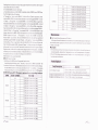
NorE oN: Receive NorE oN signals, implement the corresponding functions.
NOTE NUMBER
FUNCTION
NF1
TURN ON TIJIIN OI
TURN ON TI]IiN OI
RANKI
TURN ON IIJIiN OI
TURN
TURN
TURN
TURN
TURN
ON
ON
ON
ON
ON
BAN K2
I
Nt2
I
NF3
I
NE4
0I
II]IIN 0I :;ct
IIJIIN
IIJIIN OI
I
I
NE6
I
:;Ct NE7
II'IIN 0I S;(;I NEB
II'IIN 0I :;Ct NE1
I
I
:;(:L
N E2
S;(] E N
TURN ON
E3
S;cENE1
SCENE
BANKl
5
TURN ON
SCF N
TI.JRN ON
SCENE4
N
---,9 rrtrrrra
123
TURN ON TURN OFF SCFNF6
TURN ON TURN OFF SCENET
TURN ON TURN OFF SCENEB
TURN ON TURN OFF SCENEl
TUBN ON TURN OFF SCENFl
TURN ON TURN OFF SCENF2
TURN ON TURN OFF SCENE3
TURN ON TURN OFF SCENEs
IURN ON TURN OFF SCENE6
BACKOUT
Maintenance
OCIeaning and Using Frequency of Product
ln the open the control stations or maintenance work before they begin to make sure
the consoie power supply disconnected, the console's internal use vacuum cleaner
at least once a year.
OComplain
l.The salesman wilicheck the details of complained problem, included the item
no_
delivered quantity. deliverytime- faultyand picttrres, and the requirement of customer
2.oc and rechnology department willanalysis the complained problem, and give a
f
inalsoluiion to customer.
Faulty Disposal
Faulty Description
ontrol doesn't work
le or multiple channelfailLrr
or multi
1.Cher;k it the Jrower is correctly connected?