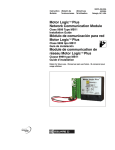
1
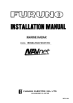
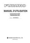
Back
SAFETY INSTRUCTIONS
WARNING
WARNING
Do not open the equipment
unless totally familiar with
electrical circuits and
service manual.
ELECTRICAL
SHOCK
HAZARD
Radio Frequency
Radiation Hazard
The radar scanner emits electromagnetic
radio frequency (RF) energy which can be
harmful, particularly to your eyes. Never
look directly into the scanner aperture from
a close distance while the radar is in
operation or expose yourself to the transmitting scanner at a close distance.
Only qualified personnel
should work inside the
equipment.
Wear a safety belt and hard
hat when working on the
scanner unit.
Distances at which RF radiation levels of
100 and 10 W/m2 exist are given in the
table below.
Serious injury or death can
result if someone falls from
the radar scanner mast.
Note: If the scanner unit is installed at a
close distance in front of the wheel house,
your administration may require halt of
transmission within a certain sector of
scanner revolution. This is possible — Ask
your FURUNO representative or dealer to
provide this feature.
Construct a suitable service platform
from which to install the scanner unit.
Serious injury or death can result if someone falls from the radar scanner mast.
Turn off the power at the mains switchboard before beginning the installation.
Fire, electrical shock or serious injury can
result if the power is left on or is applied
while the equipment is being installed.
Radiator
type
Distance to
100 W/m2
point
Distance to
10 W/m2
point
XN12A
(4')
Worst case
0.5 m
Worst case
7.5 m
Do not install the display unit where it
may get wet from rain or water splash.
XN13A
(6')
Worst case
0.3 m
Worst case
7.0 m
Water in the display unit can result in fire,
electrical shock or equipment damage.
i
CAUTION
WARNING
Ground the equipment to
prevent electrical shock and
mutual interference.
Be sure that the power supply is
compatible with the voltage rating of
the equipment.
Connection of an incorrect power supply
can cause fire or equipment damage. The
voltage rating of the equipment appears
on the label above the power connector.
Observe the following compass safe
distances to prevent deviation of a
magnetic compass:
Use only the specified power cable.
Fire or equipment damage can result if a
different cable is used.
Standard
Steering
Display
unit
1.10 m
0.80 m
Scanner
unit
1.00 m
0.75 m
HIGH TENSION WARNING
DANGER
Electrical shock hazard.
Do not touch parts in side this cover.
Name: Warning Label
Type: 14-055-4202-1
Code No.: 100-245-221
ii
TABLE OF CONTENTS
EQUIPMENT LISTS .............................................................................................. iv
SYSTEM CONFIGURATION................................................................................. vi
SCANNER UNIT
Mounting Considerations, Precautions ...............................................................................................1
Mounting Methods.............................................................................................................................1
Fixing Holes Mounting Platform........................................................................................................1
Fastening the Radiator to the Radiator bracket....................................................................................2
Mounting the Scanner Unit ................................................................................................................2
Outside fixing holes ...........................................................................................................................2
Fixing holes inside scanner unit .........................................................................................................3
Connecting the Signal Cable ..............................................................................................................4
DISPLAY UNIT
Mounting Considerations ...................................................................................................................6
Tabletop Mounting.............................................................................................................................6
Bulkhead, Overhead Mounting...........................................................................................................7
WIRING ..................................................................................................................8
ADJUSTMENTS, INITIAL SETTINGS
Adjustments, Initial Settings
1.Displaying the Installation Setup menu...................................................................................9
2.Selecting a navaid ..................................................................................................................9
3.Selecting a heading sensor......................................................................................................9
4.Adjusting turning, video amplifier input level.........................................................................9
5.Aligning heading..................................................................................................................10
6.Adjusting sweep timing........................................................................................................10
7.Adjusting MBS (Main Bang Suppression) ............................................................................11
8.Entering scanner height ........................................................................................................11
9.Selecting STC curve.............................................................................................................11
10.Setting a dead sector...........................................................................................................12
11.Checking magnetron heater voltage ....................................................................................12
ARP-10 INSTALLATION
Necessary Parts................................................................................................................................13
Installation.......................................................................................................................................13
Adjustments.....................................................................................................................................14
INSTALLATION MATERIALS, ACCESSORIES, SPARE PARTS, PACKING LIST......... A-1
OUTLINE DRAWINGS ....................................................................................... D-1
INTERCONNECTION DIAGRAM........................................................................ S-1
iii
EQUIPMENT LISTS
Standard Supply
Type
Code No.
Mass
(Kg)
XN12A-RSB-0072-060
-
23
XN13A-RSB-0072-060
-
25
XN12A-RSB-0073-060
-
23
RDP-122
-
13
Name
Scanner
Unit
Display Unit
CP03-18400
000-086-892
CP03-18410
000-086-893
CP03-18420
000-086-894
CP03-18430
000-086-895
Installation
Materials
Qty
Remarks
24 rpm, 1250 mm
Select
24 rpm, 1800 mm
one
48 rpm, 1250 mm
1
CP03-18401,
Power cable,
10 m signal cable
CP03-18401,
Power cable,
Select 15 m signal cable
one CP03-18401,
Power cable,
20 m signal cable
CP03-18401,
Power cable,
30 m signal cable
FP03-02910
Accessories
FP03-05310
000-085-767
1set FP03-04310
FP03-02920
Spare Parts
SP03-10200
000-085-692
iv
1set For display unit
Optional Supply
Name
External Buzzer
Rectifier
Type
Code No.
OP03-21
RU-3423
000-030-097
000-030-443
MJ-A6SPF0007-100
000-125-237
MJ-A6SPF0012-050
000-134-424
MJ-A6SPF0012-100
000-133-817
MJ-A6SPF0009-100
000-125-236
Signal Cable
MJ-A6SPF0003-050
000-117-603
EMI Filter
Dust Cover
Hood w/Lens
Filter
FP03-05500
03-038-9001
OP03-120
FP03-02920
008-456-990
000-801-826
008-441-880
008-224-760
Auto Plotter
ARP-10
000-086-852
Radar Plotter
RP-110
-
Cable Assy.
Slave Display
Remote Display
Cable Assy.
FMD-811
FMD-8010
FMD-1800
MJ-B24LPF0006-005
Remarks
For heading sensor, 10 m w/6P
connector at both ends, straight
For navaid, video sounder, 5 m
w/6P connector at both ends,
cross
For navaid, video sounder, 10
m w/6P connector at both
ends, cross
For navaid, video sounder,
heading sensor, 10 m w/6P
connector at one end
5 m, w/6P connector on one
end
Useable with 24 rpm scanner
unit
LCD
w/CVD Converter
000-140-438 Cable converter connector
v
SYSTEM CONFIGURATION
SCANNER UNIT
XN12A-RSB-0072-060
XN13A-RSB-0072-060
XN12A-RSB-0073-060
Signal Cable MJ-B24LPF0005
(10 m, 15 m, 20 m,
30 m, 10 m standard)
Radar Plotter
RP-110
Auto Plotter
ARP-10
(built in
display unit)
Gyro
Converter
AD-100
DISPLAY UNIT
RDP-122
100/110/115/220/
230 VAC, 1∅, 50/60 Hz
12/24/32 VDC
Remote Display
FMD-1800
Gyrocompass
Heading Sensor
C-2000
PG-2000
IEC 1162*
Rectifier
RU-3423
Video Sounder
IEC 1162*
03S9235-1
CVD Converter
RP-6065B
Navigator
IEC 1162*
Slave Display
FMD-811
FMD-8010
External
Buzzer
OP03-21
Broken lines denote optional equipment.
* Equivalent to NMEA 0183
vi
SCANNER UNIT
• Do not paint the radiator aperture, to ensure proper emission of the radar waves.
• When this radar is to be installed on larger
vessels, consider the following points:
• The signal cable run between the scanner and the display comes in lengths of
10 m (standard), 15 m, 20 m and 30 m.
Whatever length is used it must be unbroken; namely, no splicing allowed.
• Deposits and fumes from a funnel or
other exhaust vent can adversely affect
the aerial performance and hot gases
may distort the radiator portion. The
scanner unit must not be mounted where
the temperature is more than 70°C.
Mounting Considerations,
Precautions
• The scanner unit is generally installed either on top of the wheelhouse or on the radar mast on a suitable platform. Locate the
scanner unit where there is a good all-round
view. Any obstruction will cause shadow
and blind sectors. A mast for instance, with
a diameter considerably less than the width
of the radiator, will cause only a small blind
sector, but a horizontal spreader or
crosstrees in the same horizontal plane as
the scanner unit would be a much more
serious obstruction; you would need to
place the scanner unit well above or below
it.
• It is rarely possible to place the scanner unit
where a completely clear view in all directions is available. Thus, you should determine the angular width and relative bearing
of any shadow sectors for their influence
on the radar at the first opportunity after
fitting.
• If you have a radio direction finder on your
boat, locate its scanner clear of the scanner unit to prevent interference to the direction finder. A separation of more than
two meters is recommended.
• To lessen the chance of picking up electrical interference, avoid where possible routing the signal cable near other onboard
electrical equipment. Also avoid running
the cable in parallel with power cables.
• A magnetic compass will be affected if
placed too close to the scanner unit. Observe the following compass safe distances
to prevent deviation of a magnetic compass: Standard compass, 1.00 m, Steering
compass, 0.75 m.
Mounting Methods
As shown in the figure below, the scanner unit
may be installed on the bridge, on a common
mast or on a dedicated mast.
(a) On bridge
(b) Common mast (c) Dedicated mast
Figure 1 Scanner unit mounting methods
Fixing Holes in Mounting
Platform
Referring to the outline drawing on page D1, drill five holes in the mounting platform:
four holes of 15 mm diameter for fixing the
scanner unit and one hole of 25-30 mm diameter for the signal cable.
1
Fastening the Radiator to the
Radiator Bracket
Mounting the Scanner Unit
The scanner unit can be mounted using the
fixing holes on the outside (200 x 200 mm)
or inside (140 x 150 mm) the scanner unit.
For your reference, scanner unit installation
materials list appears on page A-8.
1. Remove the radiator cap from the radiator
bracket.
2. Coat contacting surface between scanner
radiator and radiator bracket with anticorrosive sealant as shown below.
Ship's Bow
RADIATOR BRACKET
(top view)
Ship's Bow
Figure 4 Mounting of Scanner Unit
10mm
Outside fixing holes
Coat hatched area with
anticorrosive sealant.
Use the hex. bolt (supplied) to mount the scanner unit as below.
Figure 2 Coating the scanner bracket with
anticorrosive sealant
1. Lay the corrosion-proof rubber mat (supplied) on the mounting platform.
3. Coat threaded holes on the scanner radiator with anticorrosive sealant.
Ground
terminal
4. Grease the O-ring and set it to the radiator
bracket.
Rubber
mat
5. Lay the scanner radiator on the radiator
bracket.
Bow mark
Figure 5 Location of rubber mat
6. Coat the radiator fixing bolts (4 pcs.) with
anticorrosive sealant. Fasten the scanner
radiator to the radiator bracket with the
radiator fixing bolts, flat washers and
spring washers.
2. Lay the scanner unit on the mounting platform, orienting it as shown in Figure 6.
Scanner
radiator
O-ring
Radiator bracket
Flat washer
Spring washer
Hex head bolt
(M8 x 30)
Coat threaded
holes with anticorrosive
sealant.
BOW
STERN
Coat bolts with
anticorrosive
sealant.
Figure 6 Scanner unit
Figure 3 Fastening the radiator bracket to
the scanner unit chassis
2
6. Prepare ground point in mounting platform
(within 300 mm of ground terminal on
scannere unit) using M6 x 25 bolt, nut and
flat washer.
CAUTION
Do not lift the antenna unit by the
radiator; lift it by the housing.
7. Run the ground wire (RW-4747, 340 mm)
between the ground terminal and ground
point.
The radiator may be damaged.
8. Coat ground terminal and ground point
with silicone sealant as shown in Figure
9.
3. Insert four hex bolts and seal washers from
the top of the scanner housing. Insert the
seal washers with the larger diameter next
to the bolt heads. Be sure the seal washer,
not other washers, is next to the bolt head.
Hex bolt
Flat washer
Ground
terminal
Silicone
sealant
Flat washer
Spring washer
Hex nut
OR
GROUND
POINT
Hex nut
Spring washer
Flat washer
Hex nut
Ground
wire
Weld here.
Hex bolt
GROUND
TERMINAL
Seal washer
Flat washer
Spring washer
Ground
wire
Nut
Scanner
unit
Figure 7 Fixing the scanner unit chassis
4. Pass flat washers, spring washers and nuts
onto hex bolts. Fasten by tightening nuts.
Do not fasten by tightening the hex bolts;
seal washers may be damaged.
Figure 9 How to coat ground point and
ground terminal with silicone sealant
Fixing holes inside scanner
unit
Seal washer
Rubber mat
Flat washer
Silicone
sealant
Scanner
unit
Mounting
platform
Silicone
sealant
This method requires removal of the RF unit
in the scanner unit to access inside fixing
holes. Use hex. bolts, flat washers, spring
washers and nuts (local supply) to mount the
scanner unit, confirming length of bolts.
Figure 8 How to fasten scanner unit to
mounting platform
5. Coat flat washers, spring washers, nuts and
exposed parts of bolts with silicone sealant.
3
1. Loosen four scanner bolts to open the
scanner unit.
Refer to Figure 11 for location.
Hex. bolt
M8X25 SUS
2 pcs.
Connecting the Signal Cable
Only the signal cable runs from the display
unit to the scanner unit. In order to minimize
the chance of picking up electrical interference, avoid where possible routing the signal
cable near other onboard electrical equipment.
Also, avoid running the cable in parallel with
power cables. Pass the cable through the hole
and apply sealing compound around the hole
for waterproofing.
Upper chassis
RF unit
Hex. bolt
M10X20 SUS
4 pcs.
Spring Washer
M10 SUS
4 pcs.
Pan head screw
M3X8 4 pcs.
Cover
Square bushing
Lower chassis
1. Open the scanner cover by loosening four
scanner bolts, and then fix the stay.
Figure 10 Scanner unit chassis, upper
chassis separated
2. Unplug connector connected between upper and lower chassis.
3. Separate upper chassis from lower chassis by removing two hex. bolts.
Stay
4. Remove cover by unfastening four pan
head screws.
Cable gland
5. Remove connector from RF unit.
6. Remove RF unit by unfastening four hex.
bolts.
Scanner
Bolt
7. Lay the corrosion-proof rubber mat (supplied) on the mounting platform.
8. Fasten the lower chassis to the mounting
platform with hex. bolts, spring washers,
flat washers and nuts (local supply), and
then coat flat washers, spring washers, nuts
and exposed parts of bolts with silicone
sealant.
Figure 11 Scanner unit chassis,
cover opened
2. Fabricate the signal cable as shown below.
Tubing
Cut a slit in rubber bushing to insert bolts.
Seal washers are not required.
9. Reassemble RF unit, cover and upper
chassis.
Vinyl
sheath
10. Set four knob caps (supplied) into outside
fixing holes.
About 370 mm
About
210 mm
Figure 12 Fabrication of signal cable
3. Unfasten the cable gland assembly (plate,
gasket, flat washer).
11. Do steps 6-8 in “Outside fixing holes”.
4. Pass the signal cable w/connector through
the bottom of the scanner unit chassis. Pass
the cable through the gland assembly as
shown below.
4
8. Pass the signal cable through the cable
protector.
Bolt
Cable
protector
4-M4 X 16
Plate
Gasket
Flat
washer
Figure 13 Passing the signal cable through
the cable gland assembly
Figure 16 Scanner unit chassis,
cover opened
5. Fasten the crimp-on lug on the shield to
one of the fixing bolts of the cable gland
assembly.
9. Connect the signal cable to the RTB Board
(03P9249), referring to the interconnection
diagram and the figure below.
6. Position the signal cable so that no more
than 4 cm of the sheath is exposed as
shown in the figure below. Tighten fixing
bolts.
10. Attach three EMI cores to the signal cable
as shown below.
J821 VH9P
J824 NH13P
Tubing
Lead in
cable here.
Shield
EMI core
RFC-13
Sheath
Bolt
Within 4 cm
J823 VH4P
Clamp
Route cable along here.
Figure 17 Scanner unit chassis,
cover opened
Plate
Gasket
Flat
washer
11. Fix the signal cable with the cable clamp.
CABLE GLAND
12. Release the stay and close the cover.
Loosely fasten the cover fixing screws;
you will have to make some adjustments
inside after completion of wiring.
Figure 14 How to fix signal
cable in cable gland
Note: When closing the cover, set the gaskets
to grooves in the bottom chassis, then tighten
bolts.
7. Unfasten four screws shown in the figure
below.
BOTTOM
CHASSIS
Four screws
GROOVE
GASKET
SCANNER BOLT
Figure 15 Scanner unit chassis,
cover opened
Torque : 9.8 ± 0.1N
5
m
DISPLAY UNIT
Mounting Considerations
Tabletop Mounting
The display unit can be mounted on a tabletop, a bulkhead or on the overhead. When selecting a mounting location, keep in mind the
following points:
1. Unfasten the two bolts at the front of the
display unit to dismount the mounting
base.
2. Using the mounting base as a template
mark fixing holes in the mounting location.
• Select a location where the display unit can
be viewed and operated conveniently and
where the screen can be viewed while facing towards the bow.
• Locate the equipment away from places
subject to water splash and rain.
• The display unit weighs 13 kg. Be sure the
mounting location is strong enough to support the weight of the unit under the continued vibration which is normally
experienced on the ship. If necessary reinforce the mounting location.
• Leave sufficient space on the sides and rear
of the unit to facilitate maintenance. Also,
leave a foot or so of “service loop” in cables
behind the unit so it can be pulled forward
for servicing or easy removal of connectors.
• A magnetic compass will be affected if
placed too close to the display unit. Observe the following compass safe distances
to prevent deviation of a magnetic compass: Standard compass, 1.0 m, Steering
compass, 0.8 m.
3. Fasten the mounting base to the tabletop
with M10 bolts or coach screws.
4. Set the display unit to the mounting base
and fasten it with the bolts removed at step
1.
DISPLAY
UNIT
M8 x 40 hex bolt
Cap
Mounting base
M10 bolts
or coach
screws
120
160
100
Figure 17 Tabletop mounting of
display unit
6
Bulkhead, Overhead Mounting
The display unit is shipped ready for mounting on a tabletop. However, it may also be mounted
on a bulkhead or on the overhead, following the illustration below.
M10 hex bolt,
spring washer,
flat washer
Fixing
plate
Mounting
base
M8 x 40 hex bolt (2 pcs.)
M6 x 16 hex
bolts (4 pcs.)
DISPLAY
UNIT
M4 x 10
cosmetic screws
(4 pcs.)
Cover
Figure 18 Bulkhead, overhead mounting
7
WIRING
All wiring are terminated at the rear of the display unit. Connect the scanner unit, power supply
and external equipment, referring to the drawing below for connector location. Be sure to ground
the display unit.
CAUTION
Use the power cable supplied with the
radar.
Ground the equipment to
prevent electrical shock and
mutual interference.
External equipment connector
(Slave display, Remote display)
DJ connector
(Scanner)
Gyrocompass
connector
NMEA I/O connector
(Navigator, see below)
NMEA connector
(Video Sounder,
see below)
Earth terminal
INT Board
Power
connector
SPU Board
(RSD, TLL)
Navigator
(Plotter)
(L/L, WP...)
Video
Sounder
Power fuse F1351*
10A: 24/32 VDC
15A: 12 VDC
* The display unit is shipped
for connection to a 12 V
ship’s mains, and a 15A fuse
is inserted in the fuse holder.
For 24/32 V ship’s mains, replace the 15A fuse with the
10A fuse (supplied).
Depth, water
temperature
Figure 19 Display unit, rear view
8
ADJUSTMENTS, INITIAL SETTINGS
5. Select menu item with the trackball and
press the [ACQ/ENTER] key.
Adjustments, Initial Settings
1. Displaying the Installation Setup
menu
6. Select menu option with the trackball and
press the [ACQ/ENTER] key to register.
Most adjustments and initial settings may be
completed on the Installation Setup menu, and
you can display this menu as follows:
2. Selecting a navaid
1. Select 1. Nav Talker on the Installation
Setup menu and press the [ACQ/ENTER]
key.
1. Press the HM OFF control while turning
on the power. Release the control when
you hear a beep.
2. Select type of navaid connected to the radar; All, GPS or LC (Loran C). “All” displays GPS and Loran C position data
alternately.
2. Press the [MENU] key. The MAIN menu
appears.
SSel by T-ball & press ENT.S
3. Press the [ACQ/ENTER] key.
RINGS
INDEX
LINE
DISP
DATA
INT
REJECT
ARP-10
MENU
OTHERS
MENU
3. Selecting a heading sensor
Change brill
from 3 to max.
1. Select 4. Hdg Sensor on the Installation
Setup menu and press the [ACQ/ENTER]
key.
Figure 20 Main menu
3. Select OTHERS menu with the trackball
and press the [ACQ/ENTER] key.
2. Select type of heading sensor connected
to the radar; magnetic compass (for example, C-2000, PG-1000) or gyrocompass
(requires AD-10 Gyro Converter).
4. Select 23. Installation Setup menu with the
trackball and press the [ACQ/ENTER]
key.
3. Press the [ACQ/ENTER] key.
[Installation Setup]
Select item by T-ball
and press ENT key.
1. Nav Talker
All
2. Depth Unit
m
3. Temp Unit
˚C
4. Hdg Sensor
Magnet
5. Key Beep
Off
6. Ant on Tx
Rotate
7. Dead Sector
180˚~180˚
8. Tune/Video Auto Adjustment
9. Heading Alignment
10. Sweep Timing Adjustment
11. MBS Adjustment
Low
12. Ant Height
13. STC Curve
Sharp
14. Oper Mode
Master
000001.5H
15. Hours in Use
000000.0H
16. Tx Hours
GPS
fa
˚F
Gyro
On
Stop
Mid
Std
4. Adjusting tuning, video amplifier
input level
LC
ft
Do the following to automatically adjust tuning and video amplifier level input.
1. Press the [STBY/TX] key to transmit.
2. Select 8. Tune/Video Adjustment on the
Installation Setup menu and press the
[ACQ/ENTER] key. The unit automatically adjusts tuning and video amplifier
input level, displaying the following message:
Hig
Gntl
Slave
Figure 21 Installation Setup menu
9
[Tune/Video Auto Adjustment]
Now under correction.
Return to installation setup
menu after the correction.
Figure 22 Tune/video auto
adjustment message
3. When adjustment is completed, the message disappears.
5. Aligning heading
You have mounted the scanner unit facing
straight ahead in the direction of the bow.
Therefore, a small but conspicuous target dead
ahead visually should appear on the heading
marker (zero degrees).
In practice, you will probably observe some
small bearing error on the display because of
the difficulty in achieving accurate initial positioning of the scanner unit. The following
adjustment will compensate for this error.
1. Identify a suitable target (for example, ship
or buoy) at a range between 0.125 to 0.25
nautical miles, preferably near the heading marker. To lessen error, keep echoes
in the outer half of the picture by changing the range. Also, be sure the zoom and
off center functions are off.
6. Adjusting sweep timing
This adjustment ensures proper radar performance, especially on short ranges. The radar
measures the time required for a transmitted
echo to travel to the target and return to the
source. The received echo appears on the display based on this time. Thus, at the instant
the transmitter is fired, the sweep should start
from the center of the display (sometimes
called sweep origin).
A trigger pulse generated in the display unit
goes to the scanner unit through the signal
cable to trigger the transmitter (magnetron).
The time taken by the signal to travel up to
the scanner unit varies, depending largely on
the length of the signal cable. During this period the display unit should wait before starting the sweep. When the display unit is not
adjusted correctly, the echoes from a straight
local object (for example, a harbor wall or
straight pier) will not appear with straight
edges – they will be seen as “pushed out” or
“pulled in” near the picture center. The range
of objects will also be incorrectly shown.
(1) Correct
2. Select 9. Heading Alignment on the Installation Setup menu and press the [ACQ/
ENTER] key. The following message appears:
[Heading Alignment]
Set EBL1 to center of target
dead ahead and press ENTER.
Correction
0.0°
<Press MENU for inst setup>
Figure 23 Heading alignment message
3. Operate the trackball to bisect target selected at step 1 with the heading marker.
4. Press the [ACQ/ENTER] key.
5. As a final test, move the boat towards a
small buoy and confirm that the buoy
shows up dead ahead on the radar when it
is visually dead ahead.
(2) Target pushed (3) Target pushed
inward
outward
Figure 24 Examples of improper and
correct sweep timing
1. Transmit on the shortest range and confirm that the [GAIN] and [A/C SEA] controls are properly adjusted.
2. Visually select a target which forms a
straight line (for example, harbor wall,
straight pier).
3. Select 10. Sweep Timing Adjustment on
the Installation Setup menu and press the
[ACQ/ENTER] key. The following message appears:
10
8. Entering scanner height
[Sweep Timing Adjustment]
Use T-ball to straighten
target and press ENTER key.
Correction
The STC effect changes with respect to scanner height above the waterline. Enter scanner
height above the waterline to optimize the
STC effect.
0.000 nm
<Press MENU for inst setup>
1. Select 12. Ant Height on the Installation
Setup menu and press the [ACQ/ENTER]
key.
Figure 25 Sweep timing adjustment message
4. Operate the trackball to straighten the target selected at step 2, and then press the
[ACQ/ENTER] key.
2. Select scanner height above the waterline;
Low (3 m or less), Mid (3 to 6 m) or High
(6 to 10 m).
7. Adjusting MBS (Main Bang
Suppression)
3. Press the [ACQ/ENTER] key.
Main bang, a large filled circle which appears
at the display center on short ranges, can be
suppressed as follows:
9. Selecting STC curve
The STC effect changes with respect to the
scanner height above the waterline. The default STC curve can be maintained in most
cases. If necessary the STC curve can be
changed as follows:
1. Transmit on long range about 10 minutes.
2. Adjust the gain to show a small amount of
noise on the display.
1. Select 13. STC Curve on the Installation
Setup menu and press the [ACQ/ENTER]
key.
3. Change to the 0.125 nautical mile range
and adjust the [A/C SEA] control.
4. Select 11. MBS Adjustment on the Installation Setup menu and press the [ACQ/
ENTER] key. The following message appears:
2. Select STC curve desired;
Sharp: The effective range of the [A/C
SEA] control is relatively short.
Std: Between Sharp and Gentle.
Gntl (Gentle): The effective range of
the [A/C SEA] control is relatively long.
3. Press the [ACQ/ENTER] key.
[MBS Adjustment]
Set value by T-ball
and press ENTER key.
Correction
000
<Press MENU for inst setup>
Figure 26 MBS adjustment message
5. Operate the trackball to suppress main
bang (adjustment range: 000 to 025).
6. Press the [ACQ/ENTER] key.
11
10. Setting a dead sector
1. Turn on the radar and leave it in stand-by.
When the scanner is installed at a close distance in front of the wheelhouse, the radar
should be set not to transmit within that area,
because no echoes appear in that area.
2. Open the scanner cover.
3. Unfasten four screws to remove the RF
section cover.
1. Select 7. Dead Sector on the Installation
Setup menu and press the [ACQ/ENTER]
key.
DANGER
ELECTRICAL SHOCK HAZARD
2. Operate the trackball to enter starting point
of sector (in figures).
This check is done with the
power on — DO NOT touch
the magnetron.
3. Press the [ACQ/ENTER] key.
4. Operate the trackball to enter ending point
of sector (in figures).
Magnetron
5. Press the [ACQ/ENTER] key.
Four screws
Note: The dead sector graphic can be turned
on/off on the OTHERS menu. For further details, see the Operator’s Manual.
Figure 25 Scanner unit, cover opened
4. Connect a multimeter, set to 10 VDC
range, between test point J825#4 and
J825#6(GND) on the RTB Board
(03P9250).
Dead
sector
Figure 24 Dead sector
Measure voltage
at this connector
(J825).
11. Checking magnetron heater
voltage
Magnetron heater voltage is formed on the
MD Board (03P9237) of the scanner unit, and
is preadjusted at the factory for use with any
length of signal cable. Therefore no adjustment is required. However, check magnetron
heater voltage as follows:
Figure 26 Scanner unit, cover removed
5. Confirm the meter reads 7.5 V ±0.1 V.
6. Close the scanner cover and tighten the
cover fixing screws.
12
ARP-10 INSTALLATION
Necessary Parts
Installation
The Auto Plotter ARP-10 is an optional circuit board which is accommodated in the display unit of the FR-7062 to provide manual
or automatic acquisition of 10 radar targets.
1. Unfasten six screws to remove the display
unit cover.
2. Mate connector J107 on the SPU Board
with connector P107 on the ARP-10
Board.
ARP-10 Installation Kit (000-086-852)
Part
Type
Code No.
Qty
ARP-10
Board
18P9007
008-476-930
1
Spacer
SQ-20
000-801-650
3
Spring
Washer
M3
C5191W
000-864-204
3
Pan Head
Screw
M3 X 8
C2700W
000-881-404
3
Pan Head
Screw
w/washer
3X8
000-805-774
SWRM10
3. Fix the ARP-10 Board with three pan head
screws (supplied).
FRONT
Pan Head
Screw
w/washer
3x8
3 pcs.
P107
REAR
ARP-10 Board
18P9007
3
J107
SPU Board
SPU9211B
Figure 30 How to install the ARP-10
Note: Spacers, spring washers and pan head
screws are not used.
In addition to the ARP-10 Board, a heading
sensor which outputs heading data in AD format in 25 msec intervals (for example,
FURUNO PG-1000) is required.
13
Adjustments
1. Turn on heading and speed sensors. Turn
on the radar and transmit.
2. Press the [MENU] key and select OTHERS menu.
3. Select 22. Self Test and press the [ACQ/
ENTER] key. Confirm that the ARP-10
test results show OK for SPEED,
COURSE, TRIGGER, VIDEO, BP and
HP.
4. Adjust the GAIN, A/C and A/C RAIN controls so FE-DATA1 and FE-DATA2 indications on the ARP-10 TEST show less
than 1,000. Also, raise/lower the gain
while watching the FE-DATA1 and FEDATA2 indications. Confirm that the FEDATA1 and FE-DATA2 indications rise/
lower according to GAIN control adjustment.
[ Self Test ]
Key test: Press each key and
check on-screen indication
lights.
ARP-10 TEST
ROM
OK 18590271xx
RAM
OK
SPEED OK NAV 0.0KT
COURSE OK
167.6°
TRIGGER OK
VIDEO
OK
BP
OK
HP
OK
MIN-HIT
0003
SCAN-TIME
0854
MAN-ACQ
00
AUTO-ACQ
00
FE-DATA1
0000
FE-DATA2
0000
Program No.
ROM
RAM
Hours in use
Tx hours
: 0359146-1XX
: OK
: OK
: 000006.9H
: 000001.1H
<Press MENU for OTHERS menu.>
Figure 31 Self test display
14
A-8
Y. Hatai
D-2
C
B
A
EXT. BUZZER
OP03-21
魚群探知機
ECHO SOUNDER
(NMEA0183)
シロ
クロ
キ
ミド
MJ-A6SPF0003,5m
MJ-A6SPF0007,10m
MJ-A6SPF0009,10m
シロ
φ6.5
クロ
キ
ミド
MJ-A6SPF0009,10m,φ6.5
MJ-A6SPF0012,5/10m,φ6.5
方位指示器
HEADING SENSOR
PG-1000
A-Dコンバータ
A-D CONVERTER
AD-100
選択 SELECT
WHT
BLK
YEL
GRN
WHT
BLK
YEL
GRN
*1
MJ-A6SPF
*1
MJ-A6SPF
1
2
3
4
5
6
1
2
3
4
5
6
1
2
3
4
5
6
DWG.No.
SCALE
APPROVED
CHECKED
DRAWN
MASS
kg
T.MATSUGUCHI
T.YAMASAKI
SWITCH BOX
(FOR RP-110)
切換器
3
CRT
U1B3 SPU-9211B
J102
NH-4P B6P_SHF_1AA_K
1
GND
2
H-SYNC
3
CRT 12V
4
VIDEO
5
V-SYNC
6
GND
J109
B3P_SHF_1AA_K
1
+12V
2
GND
3
EXT-BUZZER
J106
NH-5P B5P_SHF_1AA_K
1
GND
2
H-SYNC
3
VIDEO
4
V-SYNC
5
GND
C3460-C01- E
Dec. 19 '03
Dec. 15 '03
指示部
DISPLAY UNIT
RDP-122
J105
NH-8P B8P_SHF_1AA_K
1
GND
2
TRU-HD
3
GND
4
GP-BP
5
GND
6
OP-TRIG.
7
GND
8
OP-VIDEO
NH-3P
Dec. 15 '03
TX2-H
TX2-C
RX2-H
RX2-C
NC
GND
NMEA2 IN
J1354
DATA-H
DATA-C
CLK-H
CLK-C
NC
GND
HDG
J1353
TX1-H
TX1-C
RX1-H
RX1-C
NC
GND
NMEA1 I/O
J1352
RW-4864,0.6m,φ9.5
CO-0.2x1P,1m,
*1
MJ-A6SPF
見張警報外付ブザー
注記
1)工場にて取付済み。
2)コネクタのクランプでアースする。
3)空中線部のシールドは完全にアースする。
4)造船所支給。
5)信号ケーブルにEMIコア(3個)を取り付ける。
NOTE
1. FITTED AT FACTORY.
2. GROUND THRU CONNECTOR CLAMP.
3. GROUND EFFECTIVELY AT SCANNER UNIT.
4. SHIPYARD SUPPLY.
5. ATTACH EMI CORES(3PCS) TO SIGNAL CABLES.
ジャイロ
GYRO
J1351
1
(+)
12V - 32V DC
2
(-)
3
GND
副指示器
03S9334
REMOTE DISPLAY
5/10/15/20/30m,φ8
FMD-811他
OR OTHERS
信号変換器
RW-4864,0.6m,φ9.5
CVD CONV.
RP-6065B
シロ WHT
クロ BLK
2
*1
NJC-203-PF
航法装置
MJ-A6SPF0012,5/10m,φ6.5
シロ WHT
NAV AID
(NMEA0183)
クロ BLK
キ YEL
ミド GRN
レーダープロッタ
RADAR PLOTTER
RP-110
副指示器
REM. DISPLAY 3C-2V,30m MAX.
FMD-1800
整流器 24V
RECTIFIER + 5
RU-3423 - 6
(OPTION)
*4
IV-8SQ.
03S9235,5m,φ10
(VV-S 2.0x2C)
*4
100/110/220/ DPYC-2.5 1
230VAC,1φ
2
船内電源
SHIP'S MAINS
12/24/32V DC
1
DJ-1
13
12
*2
*4
IV-2SQ.
2C2V
YEL
NAME
名 称
TITLE
1
2
3
4
J823
B4P-VH
B.P.
MOTOR(+)
HD.
MOTOR(-)
*3
U2B6
INTERCONNECTION DIAGRAM
MARINE RADAR
03P9250
J824
NH13P B139_SHF_1AA_K
1
TUNING-IND.
2
SPARE
3
4
SPARE
5
MBS-L
6
SPARE
7
8
GND
9
10
11
12
VIDEO
13 TUNING-CONT
*5 VH2P J822
B2P-VH
1
-12
2
+12
*5
VH4P
*1 J821
VH9P B9P-VH
1
+12V
2
+12V
3
GND
4
-12V
5
-12V
6
TX-TRIG.
7
P/L-A
8
P/L-B
9
*5
NC
FR-7112
船舶用レーダー
相互結線図
ミド(太)GRN(B)
ダイ(太)ORG(B)
キ
シロ/ダイ WHT/ORG
24
21
16
6
シロ/アカ WHT/RED
アカ
RED
ダイ
ORG
シロ/チャ WHT/BRN
ムラ
PPL
シロ
WHT
アオ(太)BLU(B)
クロ
BLK
ムラ(太)PPL(B)
19
3
4
18
22
9
1
17
5
10
11
20
14
15
2
8
7
MJ-B24LPF0005,10/15/20/30m,φ11
(RW-6537,21C+2C2V,30m MAX.)
*1
キ(太) YEL(B)
クロ(太)BLK(B)
アカ(太)RED(B)
シロ(太)WHT(B)
チャ(太)BRN(B)
チャ
BRN
アオ
BLU
ミド
GRN
空中線部 ANTENNA UNIT
RSB-0072(24RPM)
RSB-0073(48RPM)
4
RW-4747
S-1
The paper used in this manual
is elemental chlorine free.
Your Local Agent/Dealer
9-52 Ashihara-cho,
Nishinomiya 662-8580, JAPAN
Telephone :
0798-65-2111
Fax
0798-65-4200
:
All rights reserved.
Printed in Japan
FIRST EDITION : APR. 1998
H2
Pub. No. IME-34600-H2
( DAMI ) FR-7112
: MAY. 18, 2005
*00080837200*
*00080837200*
*00080837200*
*IME34600H20*
*IME34600H20*
*IME34600H20*