1
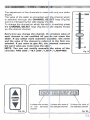
Legacy
PAOGAArvlfV1ABL E
~~ USER'S MANUAL
X
C:ONTRClLLEA
We congratulate you on vour purchase af DMX 2012.
Before proceeding of the use of this p' oduct it should be necessary ta r ead
ca re fully the following user's manual t I install it correct1y and to m ake the
most of its potentialities.
Sets of the equipment
1.1 Description of me front panel
1.2 Unpacking of the equoment
1.3 Acesseries issued with th e equipmen and relative docum enta tien
Description of the re sr panel aOO instal. ~tion
2 . 1 Description of the reer- panel
2.2 DMX 5 12 output connection
2.3 Input connection for oowe- supply
2.4 Comection of the ballast ta the electr c system
Use of t he equipmen t - modes of operat an
3 .1 PROGRAM mode
3.2 SCENE mode
3.3 MAN
3.4 MAN
PROGRAM mode
SCENE mode
Us e o f the equipmont - mein fun ctions
4.1 AdJustm ent of the RATE speed
4.2 AdjusflTlent ot the SPEED sce ed
4.3 Adlustment of the PAN and TIn char -e's through the J oystick
4 .4 Adjustm ent of the channel value
4 .5 MUSIC functi on
Use of the equipment - :>econdary functiI ns
5 .1 MEM functian
5.2 ClJ~ function
5.3 LENGTH functi an
5.4 REPEAT functi on
5 .5 BLACKlJUTfun euon
Example of work.ing - creatian of B progr, m
8 .1 Creatian of a pro gra m
Exemple of working • MENU functions
7 .1 MENU functi ons
7 .2 MENU: RESET SCANNERS
7.3 MENU: LAMP DN/LAMPOFF
7.4 MENU: CLEAR PROGRAM/SCENE
7.5 MENU: EOfT SETUP
7.6 MENU: WAD LJBRARY
•
u-.jPRO
G
]
__jSCENE]
MUSte
IEse)
~
SPEED
c.-j MAN]
RATE
T T
•
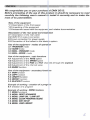
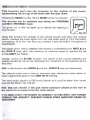
Ta activa te/deactivate the controller- storing aII t he settings.
D
D
D
Ta activate the PROGRAM m ode.
a
O
3
Ta activate the SCENE mode.
To activate the PAOG+MAN / SD:NE+MAN functio n.
Ta aetivate the MUSIC function for the d'lange of the scene to the beat of tte music.
(during MENU functions it becomes ESC key)
Ta activate the SH1FT functian and select the second function of 1/12 keys.
(duri ng MENU functi ona it becomea OK key)
1
...
iii
~~~
~~ ~
~ ~~
D
To _
I _
I ( Hl O COWUic C'SS 1
..
.
-'Y ,e
ţ~J
•••
Â
~
•
m
_ SF'UO
.
........ _ _ I'ld &CE,.;
I _
_
. . To..,..../~..... ""TE ....
D lo - . . ~ I """"" I
__
m __ •__ ...__ fr1lm o t.
i!5~
.. ""'""'" opoodI
{OI"'" - . g UI<to::n
el
_ _ """'"'"
CD DOopIay lai, • -... all lllo """""" - . . "" <hit ~ 1.....-.
m To _ .... ct>onroI' "" """"" ".., . ..... o<to
m """'""'" ._... _ _.. <1 11.- ... ....
~
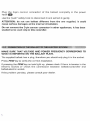
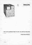
o en th e box; ta
the ballast and the documentati on out.
T ke the equipm nt out of the box as shown in th e pict re below.
· -'rot-- - -:.......- - ·:- - -
·
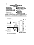
Verify the contens of th e packing.
If one of th e following parts of the pa king is missing or damaged, please,
contact your dealer immediate ly.
Al U
er 's manua l
Bl AL OS/USA Ballas
e) 5 PI
ALE - 3 PIN FEMALE Adaptor ( only for OMX 512 OUT UT )
A
8
c
J
' '1)1'.
I ~~ >
..
·.'. ...O
. ,, ~
::::-.
D
s..........OMX" 2 ~OU1PU ·-. . ~ _
a
o oe ..- .....
D
' 2 V... _
....
M .
INPUT .. ti> o"" no/. _ i_ _
.. PUT - . o 3-jIiO ,*,non CO<"O"KtOI'.
•
"'iIIIPUT·OC~".'E'''''''''''''.''.-''••••
.. . _
....
, "'
OMX "2
.. _
_ "'
M.k• • u ...
~ .. " ~
_
"'-9 .... ~_w
~" 2_ D
__.. . ._.w..
lIoo "'" . _ . _..,.,. ... - . . . _
n.
......-unu
0<1 . obl. . . ~ " . bl o 10.- 010•
_
, ,,,.,
n .
,
_poo'O'" ""'co, •
ATTUmON - ....
U.....
a l "'" - . . ... _ _m _
of ....
w ... _
--.a. "'.....,...-, ......
_
ion ....
"III"'&/i'
_"" w .
''''_
..,..,d ...... , - . ..............
_.,
_
.. -...... -----..
_ .. ---- ........... --- .'
Tho .....,,"
l"" con
""""'"*
01 "'" ""'""""'" ..
_l.ho loboI _
~. ,
~
~
~
~
cn ""'"' n"'. !oi" _
,
""
., ' _ .... ' 0
"." ,,..- ,."
.C -. . . .
OM x _ _
'"
,.,
'"
'"
~
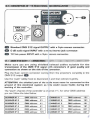
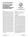
Plug the 3 -pin can non co nnect or of t he ballast comp let ly in t he power
input D
Use the "push" safety hook ta disconnect it and extra ct it gently.
ATTENTION: do not use ballast different from the one supplied, it could
cause serious damages at the internal circuitation.
Do not connect the 3-pin cannon connector in ether appliances, it has been
studied ta be used only in this centroller.
MAKE SURE THAT VOLTAGE AND POWER FREQUENCY CORRESPOND TO
WHAT IS REPORTED ON THE BALLAST PLATE.
The supplied ballast has a plug, t her efer e you should only plug it in th e socket.
Pres s POW key ta verify the correet installatio n.
If pressing the PDW key no leds Iight up, please check if there is tension in th e
elec tric socket ar check the con nec t ion between ballast-controller and
ballast-electric socket.
It the problem persists, please consult your dealer .
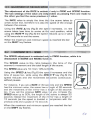
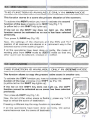
This func tion allows t a activate a progr un ar a r ange of program s
Pr essing PROG key the PROGRAM funct on is activated
(F;g. 1)
, --
-
-
-----
~ -_
The red led of PROG key will Iight up ta i rdicate th e actlvation
of t his functian.
The LCO display indicates the program VoI lrking at m oment.
If no pro gram is activate d, t he controlle gaes in BLACKOUT
MODE and th e LeD display indicates ~B L. ~ ".
Pr ess 1+12 keys ta activat e/deacti vate he program s which will be periormed
in succession .
AII seleeted pr ogram s have a lighted uţ; led. while t he acti ve pr ogr am has a
flashing led.
N.B. Each program is r epeated for a nur i ber of tlm es esta blished t hrough th e
REPEAT functi on (see par. 5 .4]
The speed of change between th e scer es can be controlled by RATE'" and
RATE 't' keys (see par . 4.1J.
The relation between th e m ovement of 1he sca nners and the pause betw een
scenes ia co ntr-olled by SPEEO .... ano SP ::ED '" keys (see par. 4 .2].
W hen the maximum ar minimum speed is r- lached the led of the SHIFT key f1ashes.
!3.11; sCENEMot fE' '''' "~::''ţ'''~ ~~
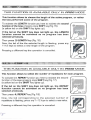
This function allaws ta see one of the 1 ! sc enes of t he program in ecticn.
N .B . If no prog r am s are selec ted t he SI :EN E functian is nat active.
Pre ssing SCENE key the SCENE functian is activated (Fig.2)
The red led of SCEN E key will lig ht up ta ind icate t he
activation of th is function.
,
@
W hen yau pass from PROGRAM mode t o SCEN E mode. the
scene active in that m oment is seleeted .
The LCD display indicates the scene work n9 at moment .
If no scene is activated . t he con troller goes in BLACKOUT
MODE and the LeD display indicates ~BU ".
Press any 1+12 keys
to activate/deactivl te Iile scene.
The speed of change between th e sceru s can be controlled by RATE'" and
RATE'" (see par. 4 .1].
W hen the maximum ar minimum speed is f"I achcd the led of the SHIFT key f1ashes.
N .B . In this funetio n SPEED ... and SPEEl J ... keys are not activated
This fun ctian allaws ta act ivate manually ane ar more scanners wh ile t he
nat selected anes ga an perfarming the PROGRAM functian .
W hen PROGRAM functi an is war king. pre ssing MAN [Fig.3 ]
key th e MAN+PRDGRAM function is activat ed.
The r ed led an PROG and MAN keys will light up ta indicate
t he act ivation of thi s functio n.
Pr essing MAN key once more you com e back in PRDG mode.
Pr ess 1+12 keys ta activate/deactivate the scanners manually controlled.
The select ed scan ners [w ith Iigth ed up led] do not follo w an ymore t he
prog ra m . but are manually controlled through the joystick, the selection of th e
channel and the slider .
Gnce it has bee n deact ivated , the sc anne r performs ag ain th e working
pro gram.
This func tian allaws t a act ivate manually ana ar more sc anners ta create ar
ta mod ify a sce ne.
When S CENE f uncti a n is w orking . pr es si ng MAN key
[fig. 4 ) th e MAN+SCENE function is activated .
The red led of SCENE and MAN keys will Iight up ta indicate
th e activati on of this functi an.
;.,;G"
MAN
Pressing MAN key onc e mo re you ca n carne back t a th e
SCENE mode.
Pressing one of the 1+12 keys the scanner manually controlled is activated .
Ta select more scanners pre ss in sequence 1+12 keys ver-y quickly. The
selected scanners [with lighted up led] can be m anually cantrolled using th e
joystick, t he channel selection and the slider.
Once anathe r scanner has been selected . th e previaus ane keeps aII ma de
sets.
The adjustment of t he RATE is activati d only În PRDG and SCENE function.
The two settings of the valu e are indip m dent as passin g from cn e mode ta
the ather you fi nd the same previous s ,It valu e.
The RATE value is simply the time t ha : th e sce ne ta kes ta
arrive et the end, theretore it is also the speed of t he change
between the ecenes.
Using th e RATE ~ key (Fig.5] the sper d rnc-e eses. i.e. th e
sce ne ta kes less t ime ta arrive at ttu end positic n. w hile
using the RATE T key (Fig.5] th e speed 'educe s up ta a velue
of 30 seconds ta end the scene.
RATE
When th e maximum and minimum speec is reached the led
an the SHIFT key flashes.
Fig . 5
The SPEEO adjust ment is activated o n l ~ in PROG fun cti an , wh ile it is
deactivated in SCENE and MUSIC funCei :In.
Th e SPEED valu e is the r at ia betwe en the t im e of t ne
scanner's movement and the total length :It th e scene.
The SPEEO value are 10: fro m 10% taH 0'/0.
Using the SPEED Â key (Rg.6 ) the spee j increases and the
time of peuse to o, while using the SPEJD "Y key [Rg .6] the
sp eed reduces and t he movement be ::om es con t inuous ,
without pauses .
For insta nce. if you set a RATE of 30 sec mds and th e SPEED
has the minimum value. the scene has a I mgth of 30 seconds
and th e movement of the rrurror- has a II ngth of 30 seconds
too . If you set th e pr evious RATE value ut you increase th e
SPEEO velue up ta 50'%. th e length of thi scene is always 3 0
seconds inste ad !:.he rnovement of the rm TOr has a tength of
15 seconds (as the speed is doubled in :omparison with the
previous onej and a pause of 15 seconds .
SPEED
Fig. 6
When th e maximum and minimum speed are rea ched th e led
on the SHIFT key f1ashes.
10
Usng the jovIU:;k U. PlIN 80d t U
lh8 e<:a'V"OIIf'". mirTOl'
The
~
oi
con bol ao:t,ueted ~ ig 7].
twe nf ţrţrbd< . - •
wth
I;llIr(MII
rolW'fl
_ .. ...,... .. .-y 80d _
poMIOrrng -.n
tha nka t o t he a op rH at.c. led .olt .... Br \t o f
mII'"'II'" ' &11. tai
~1t
~
,/,'....:':\
,®
', ' '.
.." ./,-.-
tul
The ~ 01 the mirnll' COlO be adllAltoId by
SPEED .. llnd S PfED 'f'
TIII l8 ~cte d
~ Ilo diepIoyI!d on the LCD LJo;,jJIay ......,. Iim-.
_ c h8ngot w.ptIed W ,th SPEED 0 1/0 9 t hol
jaystlek ~ the m imr w>t .. . ,.. ed ""_
WJth SPEED ~ jaywtick bllcome proportion ~
l)Ipe . i." . it 1"'" teop UlII joylIbck '" Cflnlrlll ~uon the """"'OI' keepe. d ;
-...... Ihe lTI(It'e 'JO<l '""""
lrom the ~ lhe fT"ION lhe II..,........
of ............ increas.:". Te ma"o B ma....ment 01 e 8tolp iI. 1 bol ..-.ough to lP'"'
lIOffi8 "",l1li
tel the JOYIIbd< '" the
ad dl>
,
1,.,.,
,
_ea
i1.......,
.- .
~
'
00,.
J oystick mllYe.n"nt ctlaogo tre PAN/PAN LOW ard TIt.T/TlLT lOIN' 0tLp.4
""",...
11
...
The adjustment of the channels is m ade with only one slider[Rg .B).
The value of the slider is conneeted witt the cha nnel which
is selected th rough the CHANNEl SE .ECT keys (Fig.9 a)
and it ls indicated by the LeD dispJay [Fi!;; 9 b).
Ta change the channel on which t he slid er- ie working press
t he CHANNEL SELECT keys (Fig.8 a) oi th e display shows
you the desir ed channel.
Every time you change the cha nnel, th 1 previous valu e of
each channel is not mo diti ed t ii! you do not move t he
slider . It you select more sca nner-s tt gether , the name
and the value Dt the channel is r-efer-re d ta the first one
selecte d, It you wa nt ta give All the setected sca nners
the same value you must move the slid 'r .
NOTE: You can not mod ify manually t he valu e of the
channels : PAN lOW / TILT LOW / LA" IP / LAMP-RES
•
I [ H211
CHANNEl
SE1Ecr
T
/
Fig. B
[ OLDUR2 255
It SholNS the number It shows tire nBme of
of the selecte d the selected channel
channeJ
Fig. 98
D
\
It shows tire value of
the
channel
seeceec
Fig . 9b
f .2...
~--,-----
Tll i. fu .. c ~ io n p er t ar",. tll a progra ... ţo t II. r llythm of t h. m u..i c .
• ~ d . GloiMIg rt>e
of ttl. sc:_ with th ba u be8tll.
'*'''''lI''
P1 e _ 'II lhe MUSIC
~
(Fog ' 01 lhe MlISlC fo.nX,on 15 .aMltlld
nn fun<,t;on c... bol 8CllVated onIy dunng _
_
PRClGflAM
MAN. PROGAAM mocle.
The lf'8ElI'l led OII the k"f 19U
mi" lunctlon
The ~ of
lhe dw lll'l bot •
•
M USIC
~ tll
iodocoIte !hII lItIIrtmg al
, lhe ~ "CDnVOlIed bI' the RA lY . _
OI" mirOmum lIQe8Ci is "".:hed the led
RATE ., I<ey&: _ . t.he "''''''''''''''
"" _ St1IFT I<ey " ......,.,
ltle
e-e
lJeuoJIIy. llIri'>g
MUSIC Iunction . thH &pefId 01 tho c;I\Il<"ogtI between tne
eceneoo &MuId be not sa Iow Dtl>erw<ae the ~ t of tii. ""....... wiII be
..,-
N.B. In thi5 funo;;tIon lt>e
SPeEO'" 0..:1
the ~ED ., ~ .......... <lee<:VwtBd
The lJ1t8n"4II fI'lUIIic _ ~ " " an _
IIM' ltdjustrnIlrI.
II""" .. aignaI ~ good lor tIIft OM)( 20 12 WOI1<"g
"g"'"
The inp<L muS!<;
ia .. OdB moOO/!Ite'r'8O
... Mt~· . CO. o. etc
~
_
IT IS ABSClUTELY FOR8IlDEN
tD
IIC It could bIl tuken lrom BO<JI'ld
~ of the iad< llt<InO conne<:t<>r p111<:ed
oontr'O/Ier i5 .,.,n,,,.::t.. d \O the mU8ic ............
N ,B, Only OM
""""h _
(I<l _
.......
of
ro CONNa;l' ro n.s INPIJT Am F'(MIER
S1GNALS FOR AOJUST1C SPEAKER CQMING FROM AMPLlFIED MlXER aR
I\MPllFIEA'!
)
TH1S F U N CTIO N 18 A V A l LAE-L E O N L Y IN MAN M O DE
Thi. functi on . tor•• in a """". tha pn
.""t &itlJaclon 0 1 ttIe &CIl""".....
To ~ the MEM fur1ct>on I"U NMlt" 0CWIIt.a lh6 """"",d
function oi ths
P'-'ll orce &HlfT kllY IFto 11~
"1"1
la.,.,ee.. Ied"" the SHIfT kllY rogtu ",,1
Il tIte 1"" on _
&HIFT k..., ..... nD. Iight up . _
MEM
func:tion cannet ba aot:ilIllted • • no """ .,. Il• • baan &eIecUd
.......
Then preu 1/M EM '-ey (Flg 12 1-
Now. tha settmgs e l tI>e cll. nn"'. an l thft PAN an<! T1LT
Dt aii H<:aIYW'II _ !ItoNld in a l """"""'" WW; in the
_ . , . , . , a Dt lh6 1ICtII/II 1I"DIT"'".
W eli ee tlpeOaboo .. have _
dona CO"'eCIIy. the mxIa ltl
worI<ir1l1 pass rrom MAIV mode ti> SCEt 'E mocle "" that a"'Y
......... ...,.,..., can ba o I wt . cn:.r-"" <J' " <xl",,",,
~uon
T H I8 FUNCTION 18 AVAlLAB l.E ONLY IN SCENEi M ODE
TIliH tunction ...... ti> ""I'Y tha prao.ant oc:tiva sc_
in _ h... ""a.
To 8OtMIUIltlo COPY tunet>on jOt.l h<J\/Il te /ICbvat8 tha sacond
Iunaion of lho k...,. ~ cnc.-. SH IFT :8'J (1'1\1 13 1
(a .,.,rcw Iad lin tt>e SHlFT ke'y hgtlts ""1.
.......
" _
led "" _
funcoon
""""Dt
SHIFT key __ not I Jht UJl. _ COPY
b. lOC1i.roU,d • • n o BCenI Ilo. _ n _
Then prou 2/CDPn"" (R{!.141.
N<M', tha led d lfle lICtnI!I 5<:enII '" _
Iulya te
t.ha ocene of deslinatlOn
I'J;
"'act
P re llGlflg • d,lIllrent k"l' tIl. cof'Y fur1Ctll<1
It . M the Dp8I'lltions lUMI !>een
SCHI"IfI baI;orn. .
r---,
P"""" 0"'1 1.1<,
if, ~nc "' Bd
""Ile ce
f"9CUy. the lICtIw
now th. 8<>'J'le 01 deDtinatocn .
..
THI8 F U NCT IO N 18 A VAILAB L E ONLY IN PROG MODE
This functian allows ta choose th e length of the act ive program, ar r ather
th e last perfonned s cene of t he program .
Ta activate the LENGTH functian you nave ta acuvate the seco nd
functian of the keys pre ssing onc e SHIFT key (Fig .15).
la yellow led on the SHIFT key tights up).
It th e led on the SHIFT key does not light up, the LENGTH
functi an c annot be a ctivated as no p ro g r a m ha s b e en
s e lect ed pr-evicuely.
fig . 15
Then press 3/LENGTH key (Fig.16].
New . th e led of the the selected lengtll is f1ash ing; press any
1 +12 keys ta setect a new length of the program.
Pr essing a different key the operatian is cancelled.
Fog . 16
TH I8 F U N C T ION 18 AVAILABLE O N LY IN PROG MOD E
Thi s functian allows ta select the number of repetitio ns for each program .
Ta activate the REPEAT function you have ta activare th e second
function of the keys pressing once SHIFT key [Fig. 17 ].
(a yellow led an the SHIFT key lights up).
If th e led on the SHI FT key does not light up, th e REPEA T
fun ction cannot be activated as no program has been
selecte d previou sly.
Then press
Fig. 1 7
4/REPEA Tkey (Fig. 18).
New , the led cer res pan din g t a t he setect ed nu mb er of
repetitions is tlashing; press any 1-:-12 keys te seleet a new value.
Pr essing a differe nt key the operati an is can celted.
Fig. 18
rrn. fur>ction allows to blHCk-out d eh. 5Csnnors.
Prus 12 /0lACK0Uf k"'l to &tllrt aO" n the n""",al workW>g.
Tu ~ It-. 8 /.AC1<OOTII.n::l>i:rl '/OU hav . lO ectMlllIlhIl GaCOf'Ol
function ot !ha keyo pressilg O/'II;;e SIt/FT k "{ {F"tg. 19).
(a yeJkJw lIId <In ltoIl SHlfT Icey !igIU up)
r-- - ,
ThIIn p......u 12/BLACKDUT I<ev (FIQ _20 J
Now. . . Iad& of the CU lb "''''''" ......
011 12/BlACKOUT kllY is ftesh iflg,
....-c''''''
otf. wIlIle lhu led
PI-essmg 12/9I.ACKOUT kay (Hg 20) t .. co-otroIIer returre
l.o the pr'9ViChJ8 workong
fG
A progr am is a ran ge of scenes (max 12 ) performed in succession. To creat e
[or ta modify) a program follow aII steps listed below:
1) If the controller is switc hed off, switch it on pressing POW key.
2) Press PROG key ta activare the PROGRAM function.
(t he red led on the same key will light up].
3 ) Using 1 +12 keys select only t he pr ogram t hat you want ta modify.
(only one program is f1ashing].
4) Pres s SCENE key ta activate t he SCENEfunction.
[the red led on the sam e key will light up].
5] Using 1 + 12 keys select the scene tha t you want ta modify.
6) Press MAN key to activate the MAN +SCEN E function.
(th e red leds on the MAN and SCENE keys will light up].
7] Using 1+12 keys select one or more scanners and modify t he position
wit h the joystick and t he sets of the cha nnels with t he CH.SEL. key
and the slider.
8 ) Once t he scanners have been selected and the scene has been cornplete d,
it can be stored usi ng the MEM function : press SHIFT key and th an
1/ MEM key [see par. 5 .1 ).
9 ) Now the controller is again in the SCEN E function in order that you can
select another scene or copy the scene already dane in another one [see par. 5.2)..
10) Once t he creatian of t he scenes has been finished press PROG key ta
cam e back ta the PROGRAM functian.
[the r ed led an the sam e key willligth up).
11 ] Finally. you should set th e length of the progr am usin g the LENGTH
funct ion: press onc e SHIFT key than t he 3/LENGTH key fallawed by
the numbe r of the last sta r ed scene [see par . 5 .3) .
The pr ogr am is finished; ta create ar modify others r epeat again aii the abave
ste ps.
/1
It
This function activates some special functions for the control of the
scanners and the setting of the DMX 2012 controller.
To activate the MENU function you have to activate the second
function of the keys pressing once SHIFT key [Fig.21] .
[a yellow led on t he SHIFT key Iights up] .
Then pre ss 9/MENU key (Fig.22].
Naw aII the lights of the cantraller are switched aff , while t he
leds an MUStC and SHtFf keys stay an ta indicate that in th e
MENU functions these keys beca me ESC (MUSIC) and OK
(SHIFT).
As saan as th is functian is activated, the LCD display shaws
the first functian available..
By CHANNEL SELECT keys or by the slider yau can select
between t he MENU functi ans available , which are :
RESET SCANNER: It activates RESET functian for one ar more scanners * (par .7.2)
LAMP ON: It turns ON the lamp of one ar more scanners * (par.7.3]
LAMP OFF: It turns OFF the lamp of one ar more scanners * (par.7 .3)
CLEAR PROG/SCENE: It c1ears the contents of a program ar a scene (par .7.4 )
EDIT SETUP: It allows ta modify aII the active SETUP parameters ** [par.7.5)
LOAD L1BRARY: It loads a SETUP from int ernal scanner Iibrary * * [par.7.6)
Ta exit fram MENU fun ct ian press ESC [MUS IC) key.
Ta activate the selected functian press OK (SHIFT) key.
For the specific description of the MENU functions, see the related
sections.
* It will war k only if th e scanner is pred ispased for th is functian .
* * This functian mad ify the working parameters of the controller, sa IT MUST
BE USED ONLY BY QUALIFIED PERSONNEL.
/9
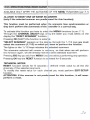
M~U:FPNctl(J!\I$;rf!l;$tt$cI!.NNi "~!§!iiti»
AVAILABLE ONLY AmR THE ACTIVATlOI I OF THE MENU FUNCTIONS {par.?1)
ALLOWS ro RESET ONE OR MORE se lNNERS.
(oo ly it the se lected scanner are pr-ecis tc eed for this functian).
This functian must be performed when t be scanners Iose synchro nization ar
they don't perform the commands of th e :antroller in a correct way.
Ta activate this fun etian you have ta ente - th e MENU functi ons ţv.p a r. 7 .1).
Thro ugh t he CHANNEL SELECT keys ar by t he slider yau m ust seleet on the
display th e "RESET SCANNER" functian.
Pre ssing OK (SHIFT) the functian ie enter sd.
"SELECT SCANNER" appears on th e d i s~ ay, through the 1/ 12 keys you mu st
select the scanne rs (1 /12] on whi ch ya 1 w ant ta perform the functian .
The lights on t he 1/ 12 keys indicates th e selected sc anners.
The scannere selected will remain in me mory, sa that when we witl perform
th is functi on aqam. we will alrea dy have tt 3 s ame seleeted sca nners.
Pressinq ESC key you exit from MENU func -ions without perform ing any operatian.
Pressing OK key th e RESET funeti on is ac Jvate d for 6 seconds .
TECHNICAL NOTES;
RESET tunc tlcn sen ds f or 6 sec onds 1" defin ed r eset valu e ta aII th e 20
channels of th e seiecteo scanner-s.
To m odify tne reset value for each eba t nel you must perlorrn EDIT SETUP
functian.
ATIENTlON: If the sc anner is not predis rcse d for this fu nction, it w ill never-
perform a reset.
).
n
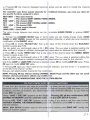
AVAl1..ABLE CNl.Y AFTER THE ACTlVATOl CF THE MENU FUNCTDNS [pal".7 .1)
ALLDWS ro CLEAR A PROGRAM IF EN' FRED FROM PROGRAM MODE OR ro
a.EAR A SlNGt.ESCENE IF ENTFRED FR"JM SCENE OR SCENE.MAN MODE.
NOn:: IICtivating th is IunctlOO wtl rie thl cootronfll" is performing PROGRAM
mode a oMlOle progr-am lS c1eared ( 12 se mes).
Act ivat ing t hi s lunction wh ila t he c m t r otle r i8 p er to r mmg SC EN E OI"
SCENE-oMAN mode a singIe eceoe is cJeYed
To aetrvate th os tunaioo you haV8 W eree - ee MENU IUrl(."t ions fv.per .7 . 1).
Ttrough tne OiANNEL SEtECT keys o- by thll ssoe- you must seIect an the
diapley ee -cLEAR PAOG/SCENE- flrct an.
Pr-essing OI( [SHIFT) h lunction ;9 cntcr'!d.
"SfLfCT PROGRAM-
Dt"
"SELfCT SCEl\ E"
Tha lIghts an
an the di6play, through
ne 11 / 1 2) ta deal".
~
tho 1/ 12 keys you must u lect the prag am/ _
ee
1/1 2 keys indIcates thf: &eIaction
an the dl&pl8y "aJ:AR ? ESC/OK- i1pp88"Si.
Pressl ng OK key the pl 1lQl81II/acene WllI oe clfIered
PrasMIg ESC kl!!'/ YOU uo!. from MENU 1'Unc1..ms WChol.t. pellDi ' IM.g aoy operation.
__
.. """"""_ .... _.. _-_.. . .-,_......_...,--....
_
__ _
_ __
..-01 . _
_
..
.....
.Tro
,,'_' 11' ""r.
_""'mt<
SETLO' ...........,."". "' /VO r I'ffC'lO IN
•
l'AfYOM'!I "'" WWWC7Jl1-..s ro
lII' llIf
I
~
""-.. _ afUC"_ _........_.. __.. .
~r ,
1. _
<ha _ _ .... _
"NU """"""" 1
"'
~"'-'a
lllt 19'1Ffl
.... "",,",,"._
..
_ _ "' .... _
;_
V '2 ....
u:CT~
............ 11/121'"' _
_
- . . .. _
J ,~
_
_
,
..._.---_
.
_-...
.
. _"__ _1__,..--.. _..
"'" _'"' "'" '1·2 .... - . . ... _ - . - .
" ' - llIt m,,,,_. _
___ ..._ ............_ '"_.....__
... 1'OE 1fUC'Jto_ ......_
~ Itl.e:ItO:;.._
•
1'OE_ .a.
_Es:J
_"" "'<0_
'-""_ID
_
.... """ _ _ ....
-_
... _- _ __ ... _...... - ...... - .... .... . _,..- __........... -_.
..-.... _- _
....... __
_
.---_
_ _._ _-_... .. _-",,
_,-,. -_
- -...
_
OOl. ".."..
-
-
oen. .. _ _
1"'"
_ _
,. " ...."
_
•
..- .,., .... ...... lIlR SEU'
""""
.. . . . . " , Of( . . . .....,. " • • •
~
~
"" "', " "
-
._
\
_
.... --,,"', "'"
"" _-""""
",,-..-... ... _
.... l:HoW'ti lIUCl'
_
...... _ _ - . . . _
O_
_
_
.... !'se _
. CW1tfOI. _
...-
...
_ _"""
_ _ M """I '" _
.........
"""""'. ~ _ ..-.. ...... _ .... -..~
....
--",
.. _ _ ""'
. . - ....... _ _. """'9' .. _ _
.. "'- ,. ID ~ .... ""'" la
"
_ _, "'" _
_
""-~
-1
, ....
", _
",
.. ... _
' ..... , .
"'" ora
~" ,
" " ' _ ... _ _
....
"> Pressing OK the cnenne! displayed
becon e active and we start te modify the channet
parameters.
The control ler uees the se special channefs for
the specific functions assigned to them.
r-edefined function s, yoo must use them for
NOf USED .> Net used channel.
.> Pan channel (SOFT CROSS/HARD ::nosSJ.
PAN
PAN lOW ·> Pan channel lDW.
nLT
.> Tilt channet lSOFT CROSS/HARD :ROSS).
TIlT LOW -> Tilt channellDW.
.> Lamp control channel.
LAMP
LAMP/RES ·> L.ike LAMP.
The veue change between two scenes can be nmediate {HARD CROSS) OI" gradual (SOFT
CIIDSS )•
CHANNEL SELECT keys or by t h slider you can moclify change mode, HARD
saR CROSS [except for th e scecer fi nction channels. In which )OU jlJffiP dlree:tly te
rnodification of the BlKOUT value].
•> Press OK to modlfy "Bl KOUT VAl- that is th ~ value of the channel wnen the BLACKOUT
•> Through the
CROSS
Of"
function is active Ipar.55).
You can eelecc ..:::::: (unchanged] value or O / 25 j value. The ::::::= value is selected ptJtting the
s1ider te O and it allows te maintain unchanged the Jutput value (no bfe ckout for this channel).
a
.,. Prese
(J( te modify "RESET VAL" tnet
the ~ Ilue of t he chennel when the MENU: RESET
functicn is active (I/.pa-. 7 .21.
You can serect ..... lunchangedl value OI" O / 251 value. The ..... value is selected putting the
slide- te and t ellows te maintain uncllanged the Ji.4lUt value (no reset far this channel).
a
Only it the lAMP OI" lAMP/RES channel is seecee 1; press OK te mo::My LAMP ON veue. Press
OK agaÎn te mod;fy LAMP OFF vaIue.
"'" PreS5ing OI< ogain you renen beck te the chal1l els seeceon and the arrow ">. is pasitioned
on me left of ee channel numbar.
New you can seect ancdler channel for the modific ltion.
NOTE: Pr1nising OK key without rmving CHANNf .. SELECT Iteys a nd th e slider you can scro!l
between cha nnel parameter& without any modffic. tion.
ro STORE ALL nE MOOlACATXJNS, REAO THE S CTDN BELDN .
TO EXIT FRDM EDIT
UPFUNCTION
To exit frcm this funetion yoo need ro press ESt: key when you ere in e e channel selection
when the arrow ">" is on t he left of the number It channel lpressing ESC key when yOO are
modifying chanr181peremete-e. ycu retom back ro the chamels selection. $O you have ta
Pf'ElGS ESC key again}.
.,
When "SAVE ? ESC/OK" appeers on th e displa' : Pressing OK aII the modiflC8tions ·ARE
STDREO IN MEMORY and th e controller exits f -cm Ula EOrT SETUP function.
Pressing ESC, "EXil? ESC/OK" sppeers an the lisplay; ~ 'JOU want II) exit from dlis fUnction
WITHOUT STORING THE MOO!FICATIONS prese OK. otherwise p-ese ESC ta retum to the
channelselection.
NOTE: EOrr SETUP function ecte an the contrt uer's
Iibr'ary of sceooe- setcps.
memor)'
and OOES NOT modify the
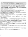
AVAILABLE ONLY AFTER THE ACTIVATION OF THE MENU FUNCTIONS (par.7.1 )
AUDWS TO LOAD A SETUP FROM LlBRARY AND STORE IT IN MEMORY.
To activate this function you have to enter t he MENU functions (v.par .7 .1).
Thro ugh the CHANNEL SELECT keys or by the slider you must select on the
display the "LOAD L1BRARY" functio n.
Press ing OK (SHIFn t he function is entered.
"SELECT SCANNER" appears on t he display, through th e 1/12 keys you must
select the scanners (1/12) on wh ich you want to perform the functian.
The lights on th e 1/ 12 keys indicates the selected scanners.
Pressing ESC key you exit from MENU functions without performing any operation.
Pressing OK key the function is aetivated.
The display shows the tirst scanner in t he Iibr ary , th rough the CHANNEL
SELECT keys or by th e slider you can seleet th e right type of scanner [ar an
equivalent) fr om t he Iibrary.
On ee se lected the sc a n ne r . press ing OK ap pears on the display
"SAVE? ESC/OK".
Pressing OK the SETUP of th e selected scanner is loaded in the memory of
the controller and activated for aII th e selected scanner .
Pr essing ESC appears an the display "EXIT ? ESC/OK"; if you want ta exit
fr om this func tion WITHOUT ANY MODIFICATION press OK key, othe rwi se
pressing ESC key you return back to t he select ion of the scanner .
NOTE: If inside the SETUP Iibrary th er e isn't your scanner ar a compatible
type, you must configure manually the SETUP of the contr oller, using t he EDIT
SETUP functian (par .7 .5).
The SETUP UBRARY is a range of SETUP [scanner) t hat can not be modified,
but only rea d.
Through LOAD L1BRARY functian yau can eopy the SETUP of t he scanner
fr om the Iibr ary to the internat memory of th e controller .
To mod ify a SETUP yau must stare it in memary thraugh th e LOAD L1BRARY
function and after modify it through the EDIT SETUP funetion.
Technical features:
Number of scanners controlled separately: 12
Numbe r of channels for each scanner: 20
Number of stared programs: 12
Number of scenes for each prog r am: 12
Total num ber of scen es: 144 (12 programs x 12 sce nes)
Positi oning way of the mirror: through a Joystick (fix or proportional mirror speed)
Channel features: Pan-Tilt 8 /16 bit - Hard/Soft cross - Reset - Lamp
Setup: Load from inte r nal library or manual set up.
Technica/ features: output signa/
Kind of output signal: DMX512/ 1990
Outp ut connector: 5-pin cannon connector
Max number of scanners connected ta the DMX output: 32
Number of DMX channels: 240 (20 ch . x 12 scanners)
Technica/ features: storage of program and settings
Kind of storage / size: FLASH memory 2 Mbit
Data maintenance without power supply: > 40 years
Climatic condition for the use
Humidity: 35% + 80%
Tempera ture : 5 + 50 °C
Power supp/y
Volta ge/ cur r ent : 12 Vdc / 240 mA
Technical fetures: audio input
Source: Inside through a built-in microphone / outside through a stereo jack
Sensitivity / input im pedance: O dB (775 mV) / 50 Kohm
Kind of level adjustment : Automatic
Dimensions and weight
Dimens ion (W x L x H) / Weight: 482 x 88 x 65 mm (2U rack) / 1 ,6 Kg.
CODEM MUS/C S.r./. - Str. Panoramica Adriatica , 10/C - 6 1 100 PESARO -ITALY
Tel. +38 072 1 24638 - Fax +380721 22CXJ42
http://www.codemmusic.com-&meil:[email protected]
AII rights r eserved. No parts of this document can be copied. photacopied or r eproduced without
the prior wntt en perrnission of the CODEM MU51C s.r .I.
No r esponibility is taken for possible inaccuracies ar mistakes.
The caDEM MUSIC s.r .I, reserves the r ight ta make any alterat ions ar aesthetics changes of th is
produet t hat seem necessary at any t ime and for whatever reason.
The caDEM MUSIC s.r.l, takes no responsibility for t he use or for t he application of this produet.