1
INSTALLATION, SERVICE AND
MAINTENANCE INSTRUCTIONS
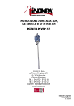
KIBER KVB-25
INOXPA, S.A.
c/Telers, 54 Aptdo. 174
E-17820 Banyoles
Girona (Spain)
Tel. : (34) 972 - 57 52 00
Fax. : (34) 972 - 57 55 02
Email: [email protected]
www.inoxpa.com
Original Manual
01.631.30.00EN_RevC
ED. 2010/09
EC DECLARATION OF CONFORMITY
(according to Directive 2006/42/CE, annex II, part A)
INOXPA, S.A.
C/ Telers, 54
17820 Banyoles (Girona) - SPAIN
Manufacturer:
Hereby declares, that the product:
HELICOIDAL PUMP
KIBER KVB-25
Name
Type
conforms to the specifications of the Council Directive:
Machine Directive 2006/42/CE, and complies with the essential requirements of the
Directive and Harmonised Standards:
UNE-EN ISO 12100-1/2:2004
UNE-EN 809/AC:2001
UNE-EN ISO 13857:2008
UNE-EN 953:1997
UNE-EN ISO 13732-1:2007
Low Voltage Directive 2006/95/EC (what repeal 73/23/CEE Directive), and are
conforms with UNE-EN 60204-1:2006 and UNE-EN 60034-1:2004
EMC Directive 2004/108/EC (what repeal 89/336/CEE Directive), and are conforms
with UNE-EN 60034-1:2004
In compliance with the Regulations (CE) nº 1935/2004, relating to materials and articles
intended to come into contact with foodstuff (repeal Directive 89/109/CEE), the materials in
contact with the product do not transfer their components in quantities which may jeopardise
consumer’s health or safety
Banyoles,
2012
1. Safety
1.1. INSTRUCTIONS MANUAL
This instruction manual contains information on the reception, installation, operation, fitting, stripping and maintenance for the
kiber KVB pump.
The information given herein is based on the most up-to-date data available.
INOXPA reserves the right to modify this instructions manual without having to give prior notice.
1.2. START-UP INSTRUCTIONS
This instruction manual contains vital and useful information for properly operating the pump and for keeping it in good
running condition.
Not only should the safety instructions set forth in this chapter be carefully read before putting the pump into operation, but
those concerned must also familiarise themselves with the operating features of the pump and strictly adhere to the
instructions given herein. It is extremely important that these instructions be kept in a set place near the installation.
1.3. SAFETY
1.3.1. Warning signs
Danger for people in general.
Danger of injury caused by rotating parts
of the equipment.
Danger! Electricity.
Danger! Caustic or corrosive agents.
Danger! Suspended loads.
Danger to the proper operating of the
machine.
Obligation to ensure safety at work.
Use of safety goggles obligatory.
1.4. GENERAL SAFETY INSTRUCTIONS
Please read the instruction manual carefully before installing and commissioning the pump. Should
you have any doubts or queries, contact INOXPA.
1.4.1. During the installation
You must always bear in mind the Technical Specifications set forth in Chapter 8.
Do not put the pump into operation before connecting it to the pipes.
Check that the motor specifications are correct, especially if there is a special risk of explosion due
to the work conditions.
During the installation procedure, all the electrical work must be carried out by duly authorised
personnel.
1.4.2. During operation
You must always bear in mind the Technical Specifications set forth in Chapter 8. The limit values that
have been set must NEVER be exceeded.
NEVER touch the pump or pipes whenever the pump is being used to decant hot liquids or during the
cleaning procedure.
The pump has moving parts. Do not put your fingers into the pump when it is operating.
ED. 2010/09
1.Safety
3
NEVER work with the suction and the delivery valves shut off.
NEVER directly sprinkle the electric motor with water. Standard motor protection is IP-55: dust and
water sprinkling protection.
1.4.3. During maintenance
You must always bear in mind the Technical Specifications set forth in Chapter 8.
NEVER strip the pump down until the pipes have been drained. Remember that there will always be
some liquid left in the pump casing (if it has not been fitted with a drain). Always remember that the
liquid that has been pumped may be dangerous or subject to high temperatures. For situations of
this type, please consult the prevailing regulations in the country in question.
Do not leave loose parts on the floor.
ALWAYS turn the power supply to the pump off before embarking on maintenance work. Take out
the fuses and disconnect the wires from the motor terminals.
All electrical work must be carried out by duly authorised personnel.
1.4.4. In accordance with the instructions
Any failure to comply with the instructions could lead to a hazard for the operators, the atmospheric conditions of the room,
and the machine, and it could lead to a loss to any right to make a claim for damages.
Such non-compliance could bring with it the following risks:
•
Important operating failures of the machine / plant.
•
Failure to comply with specific maintenance and repair procedures.
•
Potential electrical, mechanical and chemical hazards.
•
Atmospheric conditions in the room could be hazardous due to the release of chemical substances.
1.4.5. Warranty
We wish to point out that any warranty issued will be null and void and that we are entitled to an indemnity for any civil liability
claim for products which might be filed by third parties if:
•
Operation and maintenance work has not been done following the corresponding instructions; the repairs have not
been made by our personnel or have been made without our written authorization;
•
Modifications are made to our material without prior written authorization;
•
The parts or lubricants used are not original INOXPA parts/lubricants;
•
The material has been improperly used due to error or negligence or have not been used according to the indications
and the intended purpose.
•
The parts of the pump have been damaged as a result of having been exposed to strong pressure as there was no
safety valve.
The General Delivery Terms which you have already received are also applicable.
No modification can be made to the machine without the prior consent of the manufacturer. For your
safety, use spare parts and original accessories. The use of other parts exempts the manufacturer
from any and all responsibility.
Any change in operating conditions can only be done with the prior written consent of INOXPA.
In the event of doubt or should you require a fuller explanation on particular data (adjustment, assembly, disassembly...),
please do not hesitate to contact us
4
1.Safety
ED. 2010/09
2. Index
1.
Safety
1.1. Instructions manual ......................................................................................................... 3
1.2. Start-up instructions ........................................................................................................ 3
1.3. Safety ............................................................................................................................. 3
1.4. General safety instructions ............................................................................................... 3
2.
Index
3.
General Information
3.1. Description...................................................................................................................... 6
3.2. Range of applications....................................................................................................... 6
4.
Installation
4.1. Pump reception ............................................................................................................... 7
4.2. Transport and storage ..................................................................................................... 7
4.3. Location .......................................................................................................................... 8
4.4. Electrical installation ........................................................................................................ 8
5.
Start-up
5.1. Start-up .......................................................................................................................... 9
6.
Operating problems
7.
Maintenance
7.1. General maintenance ......................................................................................................11
7.2. Storage ..........................................................................................................................11
7.3. Cleaning ........................................................................................................................11
7.4. Pump disassembly/ Assembly ..........................................................................................12
8.
Technical Specifications
8.1. Technical specifications ...................................................................................................14
8.2. Weight ...........................................................................................................................14
8.3. Dimensions ....................................................................................................................15
8.4. Pump section .................................................................................................................16
8.5. Parts list ........................................................................................................................17
ED. 2010/09
2.Index
5
3. General Information
3.1. DESCRIPTION
INOXPA’s KVB-25 progressive cavity pump forms part of our range of positive-displacement pumps with helical rotor, intended
for viscous fluids. This pump is specially designed for emptying closed barrels with the connection diameter of 60mm or wider.
The hydraulic parts that form the pump are the rotor and the stator. The rotor is a round-section worm. The stator has two ribs
and its pitch doubles that of the rotor, thus allowing empty cavities between the stator and the rotor. These cavities are used
to transport the fluid. When the rotor turns within the stator, the cavities move longitudinally from the suction area to the
discharge nozzle.
This kind of pumps is suitable for pressures from 6 bar.
All pump parts in contract with the pumped product are manufactured in AISI 316L stainless steel. The stator is manufactured
in NBR, according to the FDA norm, and the standard sealing is EN 12756 mechanical seal.
This equipment is suitable for his use in food process.
3.2. RANGE OF APPLICATIONS
Q/Flow
m3/h
UK US
GPM GPM
P
[kW] [HP]
[min-1]
Each pump has a limited field of application. The pump in question was selected for certain pumping
conditions at the time the order was made. INOXPA is not liable for any damages that might arise if
the information furnished by the purchaser is incomplete (nature of the liquid, RPM…).
6
3.General Information
ED. 2010/09
4. Installation
4.1. PUMP RECEPTION
INOXPA is not responsible for any deterioration of the material as a result of its transportation or
unpacking. Visually check that the packing has not suffered any damage.
The pump will be accompanied by the following documentation:
•
Dispatch notes.
•
Pump Instruction and Service Manual.
•
Motor Instruction and Service Manual (*).
•
(*) If the pump has been supplied with a motor from INOXPA.
Unpack the pump and check the following:
• The pump suction and delivery connections, removing the remains of any packing material.
• Check that the pump and the motor have not suffered any damage.
• Should the pump not be in proper condition and/or does not have all the parts, the haulier
must draw up a report as soon as possible with regard to the same.
4.1.1. Pump identification and marking
INOXPA S.A.
C. Telers, 54 . P.O. BOX 174
17820 BANYOLES . GIRONA (SPAIN)
Tel.972 57 52 00 . Fax.972 57 55 02
www.inoxpa.com
YEAR
kW
min
3
Qm /h
Serial number
Nº
MODEL
-1
V
Hz
Hm
Pump plate
4.2. TRANSPORT AND STORAGE
Lift the pump through the drive support as is shown below:
ED. 2010/09
4.Installation
7
4.3. LOCATION
Position the pump into the barrel, always having the stator submerged.
Make sure that the pump does not work in dry because the stator will be deteriorated quickly.
4.4. ELECTRICAL INSTALLATION
Leave the connecting of the electrical motors to qualified personnel. Take the necessary measures to
prevent any breakdowns in the connections and wires.
The electrical equipment, the terminals and the components of the control systems may still carry an
electric charge even when disconnected. Contact with them may put the safety of operators at risk,
or cause irreparable damage to the material.
Before manoeuvring the pump, make sure that the electric box is switched off.
•
•
Connect the motor in accordance with the instructions supplied by the manufacturer of the same.
Check the direction of the rotation (see the signaling label on the pump).
Put the pump motor into operation momentarily. Make sure, by looking at the pump from
above, that the motor’s ventilator is rotating in a clockwise direction.
Check ALWAYS the direction of the motor’s rotation with liquid inside the pump.
8
4.Installation
ED. 2010/09
5. Start-up
Before putting the pump into operation read carefully the instructions on installation given in
Chapter 4. Installation.
5.1. START-UP
Read Chapter 8. Technical Specifications carefully. INOXPA will not assume responsibility for any
improper or incorrect use of the equipment.
Do not touch the pump or the piping while it is pumping products at a high temperature.
5.1.1. Checks to be carried out before putting the pump into operation
• Fully open the cut-off valve on the discharge pipe.
• Check that the stator is submerged.
The pump must NEVER rotate without liquid.
• Check that the rotation direction of the motor is correct.
• Check that the power supply matches the rating indicated on the motor plate.
5.1.2. Checks to be carried out on putting the pump into operation
• Check to make sure that the pump is not making any strange noises.
• Check to see if the absolute inlet pressure is sufficient, in order to avoid cavitations in the pump. Consult the curve for the
minimum required pressure above the steam pressure (NPSHr).
• Monitor the delivery pressure.
• Check that there are no leaks in the sealed areas.
Monitor motor consumption in order to avoid a circuit overload.
ED. 2010/09
5.Start-up
9
6. Operating problems
The table given below provides solutions to problems that might arise during pump operation. With respect to the same, it is
assumed that the pump has been properly installed and has been correctly selected for the application in question.
Should there be a need for technical service please contact INOXPA.
Operating problems
Probable causes
Overloading of motor.
Insufficient flow rate or pressure in pump.
Irregular discharge flow rate / pressure.
Noise and vibrations.
The pump gets clogged.
Overheating of the pump.
Abnormal wear.
Leak in mechanical seal.
3.
1,
1,
2,
3,
3,
4,
5,
Probable causes
Solutions
1
2
Wrong rotation direction.
Delivery pressure is too high.
3
4
5
6
The viscosity of the liquid is too high.
The temperature of the liquid is too high.
Mechanical seal either damaged or worn.
Unsuitable stator or O-ring for the liquid in question.
7
8
9
10
11
There are foreign bodies in the liquid.
The tension of the mechanical seal spring is too low.
The pump speed is too low.
The stator is worn out.
Very abrasive liquid.
2,
3.
3,
4,
4,
7,
6,
3, 4, 9, 10.
4, 7, 10.
7.
7.
10, 11.
8.
Change the direction of the rotation.
If necessary, decrease the load losses by increasing the diameter
of the piping, for example.
Decrease the viscosity by heating the liquid, for example.
Decrease the temperature of the liquid by cooling it.
Replace the seal.
Fit more suitable O-ring by consulting the supplier with respect to
the same.
Place a filter at the suction piping.
Adjust in accordance with the instructions given herein.
Increase the speed.
Replace the stator.
Mount the more suitable material of stator (check with the
supplier).
If the problems persist stop using the pump immediately. Contact the pump manufacturer or his
representative.
10
6.Operating problems
ED. 2010/09
7. Maintenance
7.1. GENERAL MAINTENANCE
This pump, as with any other machine, needs to be maintained. The instructions contained in this manual deal with the
identification and replacement of the spare parts. These instructions have been drawn up by maintenance staff and are
destined for those people who are responsible for supplying spare parts.
Read carefully Chapter 8. Technical specifications.
All the parts or materials that are changed must be duly eliminated/recycled in accordance with the
prevailing directives in each area.
ALWAYS disconnect the pump before starting out on any maintenance work.
7.1.1. Check the mechanical seal
Periodically check that there are no leaks in the shaft area. Should there be any leaks in the mechanical seal area, replace the
same pursuant to the instructions given in the section entitled Stripping and Assembly of the pump.
7.2. STORAGE
Before being stored the pump must be completely emptied of liquids. Avoid, as far as possible, the exposure of the parts to
excessively damp atmospheres.
7.3. CLEANING
The use of aggressive cleaning products such as caustic soda and nitric acid may give rise to skin
burns.
Use rubber gloves during the cleaning process.
Always use protective goggles.
To clean the pump manually, disassemble the pump as indicated in the Pump disassembly/assembly instructions.
In order to remove any remains of cleaning products, ALWAYS rinse the element in question with clean water after completing
the cleaning process.
ED. 2010/09
7.Maintenance
11
7.4. PUMP DISASSEMBLY/ ASSEMBLY
7.4.1. Stator, rotor
Disassembly
Insert a rod into the hole in the stator and unscrew the stator (22). Mind that it is left-threaded. Pull out
the pump casing (01) loosening the nut of the flange support (04), mind that it is also left-threaded.
Remove the rotor (21) pulling out the hexagonal screw (52) and the hexagonal nut (54).
The stator and the upper part of the casing are left threaded.
Assembly
Attach the rotor (21) to the shaft (05) and fasten it with the hexagonal screw (52), flat washer (53) and
hexagonal nut (54). Place the O-ring (80) into the casing (01) and assemble it on the flange support (04)
with a left-threaded hexagonal nut. Place the seal stop ring (31A) to the stator (22) and with help of the
rod in the hole of the stator screw it to the casing (01) till it stops, remember that it is left threaded.
7.4.2. Mechanical seal
Disassembly
Continue disassembling the pump in the horizontal position. Loosen the pin (55) of the seal stop ring (31) and slide it, pull it out
together with the rotating part of the mechanical seal (08). Remove the seal cover (09) with the stationary part of the
mechanical seal.
Assembly
Place the stationary part of the mechanical seal (08) into the housing of the seal cover (09) and then assemble it on the centre
of the flange support (04). Slide the rotating part of the mechanical seal along the shaft and the seal stop ring (31) and fix with
the pin (55) the seal stop ring (31) according to the following assembly dimensions.
12
7.Maintenance
ED. 2010/09
7.4.3. Change of drive
Disassembly
First, follow the disassembly procedure as indicated in the above section.
Remove the hexagonal screw (52A), hexagonal nut (54) and the shaft (05). Then loosen the hexagonal screws (52B and 52C)
to pull out the flange support (04) and the drive support (06).
Assembly
Drill a hole in the drive shaft (93) as indicated on the figure below. Mount the shaft (05) in the hole of the drive and fix it with
the hexagonal screw (52A) and hexagonal nut (54). Place the flange support (04) and the drive support (06) to the flange of
the drive, fasten the hexagonal screws (52B and 52C) and flat washers (53A).
ED. 2010/09
7.Maintenance
13
8. Technical Specifications
8.1. TECHNICAL SPECIFICATIONS
Flow at 900 rpm. ...................................................................
Flow at 750 rpm. ...................................................................
Flow at 500 rpm. ...................................................................
Flow at 300 rpm. ...................................................................
Maximum operating pressure ..................................................
Maximum viscosity ..................................................................
Operating temperature ...........................................................
Sound level ...........................................................................
Discharge connection .............................................................
Pump tube diameter ..............................................................
28 l/min.
23 l/min.
16 l/min.
10 l/min.
6 bar (87 PSI)
40.000 mPas
-10 ºC a +85ºC
14 ºF a 185 ºF
60-80 dB(A)
R 1 ½”
54 mm.
Materials
Stator ......................................................................................
Parts in contact with the product ...............................................
Other parts in stainless steel .....................................................
Gaskets in contact with the product ...........................................
Other optional stator materials ..................................................
Surface finish ...........................................................................
NBR black according FDA
AISI 316L
AISI 304
NBR
NBR white, EPDM
Standard polished
Mechanical seal
Type of seal ...........................................................................
Stationary part material ..........................................................
Rotary part material ...............................................................
Seals material ........................................................................
Single inside seal
Silicon
Silicon
Viton
Whenever the noise level in the area of operation exceeds 85 dB(A) use special protection.
8.2. WEIGHT
Pump type
KVB-25
14
Weight
without drive
[Kg]
Weight with
motor
[Kg]
Weight with
gear motor
[Kg]
8
36
33
8.Technical Specifications
ED. 2010/09
8.3. DIMENSIONS
ED. 2010/09
8.Technical Specifications
15
8.4. PUMP SECTION
16
8.Technical Specifications
ED. 2010/09
8.5. PARTS LIST
Position
Description
Quantity
Material
01
Pump casing
1
AISI 316L
04
Flange support
1
AISI 304
06
Drive support
1
AISI 304
08
Mechanical seal
1
-
09
Seal cover
1
AISI 316L
21
Rotor
1
AISI 316L
22
Stator
1
AISI 316L + black NBR
24
Connecting rod
1
AISI 316L
31
Seal stop ring
1
AISI 316L
Washer
1
AISI 316L
31A
52
Hexagonal screw
1
A2
52A
Hexagonal screw
1
A2
52B
Hexagonal screw
2
A2
52C
Hexagonal screw
2
A2
53
Flat washer
2
A2
53A
Flat washer
4
A2
54
Hexagonal nut
2
A2
55
Pin
1
A2
80
O-ring
1
NBR
93
Drive
1
-
ED. 2010/09
8.Technical Specifications
17
NOTES
NOTES
INOXPA, S.A.
c/ Telers, 54 – PO Box 174
17820 BANYOLES (GIRONA)
DELEGACIÓN NORD-ESTE /
Ó DEL VALLÈS (BCN)
BARBERÀ
Tel: 937 297 280
Fax: 937 296 220
e-mail: [email protected]
ZARAGOZA
Tel: 976 591 942
Fax: 976 591 473
e-mail: [email protected]
DELEGACIÓN LEVANTE
PATERNA (VALENCIA)
Tel: 963 170 101
Fax: 963 777 539
e-mail: [email protected]
DELEGACIÓN CENTRO
ARGANDA DEL REY (MADRID)
Tel: 918 716 084
Fax: 918 703 641
e-mail: [email protected]
DELEGACIÓN STA
GALDACANO (BILBAO)
Tel: 944 572 058
Fax: 944 571 806
e-mail: [email protected]
LA CISTÉRNIGA (VALLADOLID)
Tel: 983 403 197
Fax: 983 402 640
e-mail: [email protected]
LOGROÑO
Tel: 941 228 622
Fax: 941 204 290
e-mail: [email protected]
INOXPA SOLUTIONS LEVANTE
PATERNA (VALENCIA)
Tel: 963 170 101
Fax: 963 777 539
e-mail: [email protected]
INOXPA SOLUTIONS FRANCE
GLEIZE
Tel: 33 474627100
Fax: 33 474627101
e-mail: [email protected]
CHAMBLY (PARIS)
Tel: 33 130289100
Fax: 33 130289101
e-mail: [email protected]
ST. SEBASTIEN sur LOIRE
Tel/Fax: 33 130289100
e-mail: [email protected]
WAMBRECHIES
Tel: 33 320631000
Fax: 33 320631001
e-mail: [email protected]
INOXPA AUSTRALIA PTY (LTD)
MORNINGTON (VICTORIA)
Tel: 61 3 5976 8881
Fax: 61 3 5976 8882
e-mail: [email protected]
INOXPA ALGERIE
ROUIBA
Tel: 213 21856363 / 21851780
Fax: 213 21854431
e-mail: [email protected]
INOXPA SOUTH AFRICA (PTY) LTD
JOHANNESBURG
Tel: 27 117 945 223
Fax: 27 866 807 756
e-mail: [email protected]
INOXPA USA, Inc
SANTA ROSA
Tel: 1 7075 853 900
Fax: 1 7075 853 908
e-mail: [email protected]
INOXPA UK LTD
SURREY
Tel: 44 1737 378 060 / 079
Fax: 44 1737 766 539
e-mail: [email protected]
S.T.A. PORTUGUESA LDA
VALE DE CAMBRA
Tel: 351 256 472 722
Fax: 351 256 425 697
e-mail: [email protected]
INOXPA ITALIA, S.R.L.
BALLO DI MIRANO – VENEZIA
Tel: 39 041 411 236
Fax: 39 041 5128 414
e-mail: [email protected]
INOXPA SKANDINAVIEN A/S
HORSENS (DENMARK)
Tel: 45 76 286 900
Fax: 45 76 286 909
e-mail: [email protected]
IMPROVED SOLUTIONS
INOXPA INDIA PVT. LTD.
Maharashtra, INDIA.
Tel: 91 2065 008 458
Tel: 34 972575200
Fax: 34 972575502
e-mail: [email protected]
www.inoxpa.com
VALE DE CAMBRA
Tel: 351 256 472 140 / 138
Fax: 351 256 472 130
e-mail: [email protected]
INOXPA SPECIAL PROCESSING
EQUIPMENT, CO., LTD.
JIAXING (China)
Tel.: 86 573 83 570 035 / 036
Fax: 86 573 83 570 038
INOXRUS
MOSCOW (RUSIA)
Tel / Fax: 74 956 606 020
e-mail: [email protected]
INOXPA WINE SOLUTIONS
VENDARGUES (FRANCE)
Tel: 33 971 515 447
Fax: 33 467 568 745
e-mail: [email protected] /
INOXPA UCRANIA
KIEV
Tel: 38 050 720 8692
e-mail: [email protected]
DELEGACIÓN SUR
JEREZ DE LA FRONTERA (CÁDIZ)
Tel / Fax: 956 140 193
e-mail: [email protected]
[email protected]
SAINT PETERSBURG (RUSIA)
Тel: 78 126 221 626 / 927
Fax: 78 126 221 926
e-mail: [email protected]
[email protected]
INOXPA products are available from our branch offices and through a network of independent distributors covering more than 50 countries
around the World. For more information, visit our Web site:
www.inoxpa.com
This information is for guidance only. We reserve the right to modify any material or characteristic without prior notice.